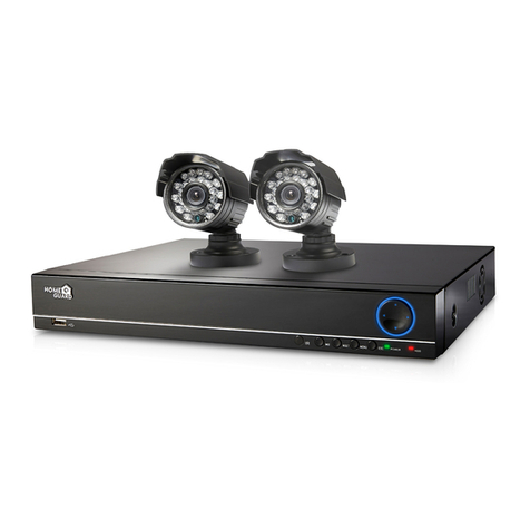
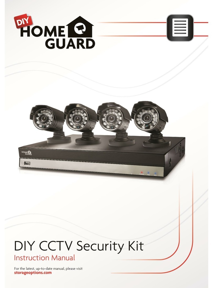
Homeguard HGDVK-44402 User manual

Heat-sensing HD CCTV Kit
Instruction Manual
For the latest,up-to-date manual, please visit
homeguardworld.com
DETECTION
SMART
MOTION & HEAT TRIGGER ACCURATE ALERTS

Safety Instruction
1 Product Overview
1.1 Rear Panel
1.2 Remote Controller (For Reference Only)
2 DVR Installation & Connection
2.1 HDD Installation
2.2 Connection Diagram
2.3 Power Supply Connection
3 DVR Common Operations
3.1 Using the Supplied Mouse
3.2 Using the Virtual Keyboard
3.3 Password
4 DVR Starting up
4.1 Start Wizard
4.1.1 Start Wizard
4.1.2 Network Configuration
4.1.3 Date/Time
4.1.4 IP Camera
4.1.5 Disk
4.1.6 Resolution
4.1.7 Mobile
4.1.8 Summary
4.2 Live View Screen Overview
4.2.1 Camera Quick Toolbar
4.2.2 Taskbar
4.2.3 Start Menu
4.2.3.1 Unlock and Lock Screen
4.2.3.2 Shutdown
5 DVR System Setup
5.1 Channel
5.1.1 Channel
5.1.1.1 Analog Channels
5.1.1.2 IP Channels
5.1.1.3 Protocol Manage
5.1.2 Live
5.1.3 Image Control
5.1.4 PTZ
5.1.1.1 PTZ control
5.1.5 Motion
5.1.6 PIR
5.1.7 Video Cover
4
5
5
6
7
7
8
8
9
9
9
10
11
11
11
11
12
13
15
15
16
16
17
18
18
19
19
19
20
20
20
20
21
22
22
23
24
25
26
28
29
5.1.8 Intelligent
5.1.8.1 PID (Perimeter Intrusion Detection)
5.1.8.2 LCD (Line Crossing Detection)
5.1.8.3 SOD (Stationary Object Detection)
5.1.8.4 PD (Pedestrian Detection)
5.1.8.5 FD (Face Detection)
5.1.8.6 CC (Cross-Counting)
5.1.8.7 Intelligent Analysis
5.1.8.8 Intelligent Schedule
5.2 Record
5.2.1 Encode
5.2.2 Record
5.2.2.1 Record
5.2.2.2 Record Schedule
5.2.3 Capture
5.2.3.1 Capture
5.2.3.2 Capture Schedule
5.3 Alarm
5.3.1 Motion
5.3.2 I/O
5.3.3 PIR
5.3.4 PTZ Linkage
5.3.5 Exception
5.4 Network
5.4.1 General
5.4.4.1 PPPoE
5.4.1.2 3G
5.4.1.3 Port Configuration
5.4.2 DDNS
5.4.3 Email
5.4.3.1 Email Configuration
5.4.3.2 Email Schedule
5.4.4 FTP
5. 5 Device
5. 5.1 Disk
5.5.1.1 Disk Group
5.5.1.2 S.M.A.R.T
5.5.2 Cloud
5.6 System
5.6.1 General
5.6.1.1 Date and Time
5.6.1.2 NTP Settings
5.6.1.3 DST Settings
5.6.2 Output Configuration
5.6.2.1 LIVE-OUT
5.6.3 Multi-user
5.6.3.1 Changing Password
5.6.3.2 Add New Users
5.6.3.3 Setting User Permissions
5.6.4 Maintenance
5.6.4.1 Log
5.6.4.2 Load Default
5.6.4.3 Upgrade
5.6.4.4 Parameter Management
5.6.4.4 Auto Reboot
5.6.5 IP Camera Maintain
5.6.5.1 Upgrade IP Camera
5.6.5.2 Load Default Settings for IP Camera
5.6.6 System Information
5.6.6.1 Information
5.6.6.2 Channel Information
5.6.6.3 Record Information
5.6.6.4 Network State
6 Search, Playback & Backup
6.1 Using Search Function
6.1.1 Search & Play Video in General
6.1.1.1 Video Clip Backup
6.1.2 Event Search, Playback & Backup
6.1.2.1 Event Playback Control
6.1.3 Sub-periods Playback
6.1.4 Smart Search & Playback
6.1.4.1 Smart Search Area
6.1.5 Picture Search & View
6.1.5.1 Picture Preview Control
7 Remote Access via Web Client
7.1 Basic System Environment Requirements
7.2 Web Plugin Download and Installation
7.3 Web Client Manager
7.3.1 Live Interface
7.3.2 Playback
7.3.2.1 Playback Control Buttons
7.3.3 Remote Setting
7.3.4 Local Setting
8 Viewing Backed Up Video on PC/Mac
9 Remote Access via Mobiel Devices
10 Appendix
10.1 Troubleshooting
10.2 Usage Maintenance
Contents 30
31
32
34
35
37
38
40
40
40
40
41
41
42
42
42
43
44
44
44
45
45
45
46
46
47
47
47
48
49
49
49
50
51
51
52
52
53
53
54
54
55
55
55
56
57
58
58
59
59
59
60
61
61
61
62
62
62
63
63
63
63
64
65
65
66
67
68
69
69
70
71
72
73
74
74
74
76
76
78
79
80
80
81
83
84
84
85
1

Safety Instruction
1 Product Overview
1.1 Rear Panel
1.2 Remote Controller (For Reference Only)
2 DVR Installation & Connection
2.1 HDD Installation
2.2 Connection Diagram
2.3 Power Supply Connection
3 DVR Common Operations
3.1 Using the Supplied Mouse
3.2 Using the Virtual Keyboard
3.3 Password
4 DVR Starting up
4.1 Start Wizard
4.1.1 Start Wizard
4.1.2 Network Configuration
4.1.3 Date/Time
4.1.4 IP Camera
4.1.5 Disk
4.1.6 Resolution
4.1.7 Mobile
4.1.8 Summary
4.2 Live View Screen Overview
4.2.1 Camera Quick Toolbar
4.2.2 Taskbar
4.2.3 Start Menu
4.2.3.1 Unlock and Lock Screen
4.2.3.2 Shutdown
5 DVR System Setup
5.1 Channel
5.1.1 Channel
5.1.1.1 Analog Channels
5.1.1.2 IP Channels
5.1.1.3 Protocol Manage
5.1.2 Live
5.1.3 Image Control
5.1.4 PTZ
5.1.1.1 PTZ control
5.1.5 Motion
5.1.6 PIR
5.1.7 Video Cover
4
5
5
6
7
7
8
8
9
9
9
10
11
11
11
11
12
13
15
15
16
16
17
18
18
19
19
19
20
20
20
20
21
22
22
23
24
25
26
28
29
5.1.8 Intelligent
5.1.8.1 PID (Perimeter Intrusion Detection)
5.1.8.2 LCD (Line Crossing Detection)
5.1.8.3 SOD (Stationary Object Detection)
5.1.8.4 PD (Pedestrian Detection)
5.1.8.5 FD (Face Detection)
5.1.8.6 CC (Cross-Counting)
5.1.8.7 Intelligent Analysis
5.1.8.8 Intelligent Schedule
5.2 Record
5.2.1 Encode
5.2.2 Record
5.2.2.1 Record
5.2.2.2 Record Schedule
5.2.3 Capture
5.2.3.1 Capture
5.2.3.2 Capture Schedule
5.3 Alarm
5.3.1 Motion
5.3.2 I/O
5.3.3 PIR
5.3.4 PTZ Linkage
5.3.5 Exception
5.4 Network
5.4.1 General
5.4.4.1 PPPoE
5.4.1.2 3G
5.4.1.3 Port Configuration
5.4.2 DDNS
5.4.3 Email
5.4.3.1 Email Configuration
5.4.3.2 Email Schedule
5.4.4 FTP
5. 5 Device
5. 5.1 Disk
5.5.1.1 Disk Group
5.5.1.2 S.M.A.R.T
5.5.2 Cloud
5.6 System
5.6.1 General
5.6.1.1 Date and Time
5.6.1.2 NTP Settings
5.6.1.3 DST Settings
5.6.2 Output Configuration
5.6.2.1 LIVE-OUT
5.6.3 Multi-user
5.6.3.1 Changing Password
5.6.3.2 Add New Users
5.6.3.3 Setting User Permissions
5.6.4 Maintenance
5.6.4.1 Log
5.6.4.2 Load Default
5.6.4.3 Upgrade
5.6.4.4 Parameter Management
5.6.4.4 Auto Reboot
5.6.5 IP Camera Maintain
5.6.5.1 Upgrade IP Camera
5.6.5.2 Load Default Settings for IP Camera
5.6.6 System Information
5.6.6.1 Information
5.6.6.2 Channel Information
5.6.6.3 Record Information
5.6.6.4 Network State
6 Search, Playback & Backup
6.1 Using Search Function
6.1.1 Search & Play Video in General
6.1.1.1 Video Clip Backup
6.1.2 Event Search, Playback & Backup
6.1.2.1 Event Playback Control
6.1.3 Sub-periods Playback
6.1.4 Smart Search & Playback
6.1.4.1 Smart Search Area
6.1.5 Picture Search & View
6.1.5.1 Picture Preview Control
7 Remote Access via Web Client
7.1 Basic System Environment Requirements
7.2 Web Plugin Download and Installation
7.3 Web Client Manager
7.3.1 Live Interface
7.3.2 Playback
7.3.2.1 Playback Control Buttons
7.3.3 Remote Setting
7.3.4 Local Setting
8 Viewing Backed Up Video on PC/Mac
9 Remote Access via Mobiel Devices
10 Appendix
10.1 Troubleshooting
10.2 Usage Maintenance
30
31
32
34
35
37
38
40
40
40
40
41
41
42
42
42
43
44
44
44
45
45
45
46
46
47
47
47
48
49
49
49
50
51
51
52
52
53
53
54
54
55
55
55
56
57
58
58
59
59
59
60
61
61
61
62
62
62
63
63
63
63
64
65
65
66
67
68
69
69
70
71
72
73
74
74
74
76
76
78
79
80
80
81
83
84
84
85
2

Safety Instruction
1 Product Overview
1.1 Rear Panel
1.2 Remote Controller (For Reference Only)
2 DVR Installation & Connection
2.1 HDD Installation
2.2 Connection Diagram
2.3 Power Supply Connection
3 DVR Common Operations
3.1 Using the Supplied Mouse
3.2 Using the Virtual Keyboard
3.3 Password
4 DVR Starting up
4.1 Start Wizard
4.1.1 Start Wizard
4.1.2 Network Configuration
4.1.3 Date/Time
4.1.4 IP Camera
4.1.5 Disk
4.1.6 Resolution
4.1.7 Mobile
4.1.8 Summary
4.2 Live View Screen Overview
4.2.1 Camera Quick Toolbar
4.2.2 Taskbar
4.2.3 Start Menu
4.2.3.1 Unlock and Lock Screen
4.2.3.2 Shutdown
5 DVR System Setup
5.1 Channel
5.1.1 Channel
5.1.1.1 Analog Channels
5.1.1.2 IP Channels
5.1.1.3 Protocol Manage
5.1.2 Live
5.1.3 Image Control
5.1.4 PTZ
5.1.1.1 PTZ control
5.1.5 Motion
5.1.6 PIR
5.1.7 Video Cover
4
5
5
6
7
7
8
8
9
9
9
10
11
11
11
11
12
13
15
15
16
16
17
18
18
19
19
19
20
20
20
20
21
22
22
23
24
25
26
28
29
5.1.8 Intelligent
5.1.8.1 PID (Perimeter Intrusion Detection)
5.1.8.2 LCD (Line Crossing Detection)
5.1.8.3 SOD (Stationary Object Detection)
5.1.8.4 PD (Pedestrian Detection)
5.1.8.5 FD (Face Detection)
5.1.8.6 CC (Cross-Counting)
5.1.8.7 Intelligent Analysis
5.1.8.8 Intelligent Schedule
5.2 Record
5.2.1 Encode
5.2.2 Record
5.2.2.1 Record
5.2.2.2 Record Schedule
5.2.3 Capture
5.2.3.1 Capture
5.2.3.2 Capture Schedule
5.3 Alarm
5.3.1 Motion
5.3.2 I/O
5.3.3 PIR
5.3.4 PTZ Linkage
5.3.5 Exception
5.4 Network
5.4.1 General
5.4.4.1 PPPoE
5.4.1.2 3G
5.4.1.3 Port Configuration
5.4.2 DDNS
5.4.3 Email
5.4.3.1 Email Configuration
5.4.3.2 Email Schedule
5.4.4 FTP
5. 5 Device
5. 5.1 Disk
5.5.1.1 Disk Group
5.5.1.2 S.M.A.R.T
5.5.2 Cloud
5.6 System
5.6.1 General
5.6.1.1 Date and Time
5.6.1.2 NTP Settings
5.6.1.3 DST Settings
5.6.2 Output Configuration
5.6.2.1 LIVE-OUT
5.6.3 Multi-user
5.6.3.1 Changing Password
5.6.3.2 Add New Users
5.6.3.3 Setting User Permissions
5.6.4 Maintenance
5.6.4.1 Log
5.6.4.2 Load Default
5.6.4.3 Upgrade
5.6.4.4 Parameter Management
5.6.4.4 Auto Reboot
5.6.5 IP Camera Maintain
5.6.5.1 Upgrade IP Camera
5.6.5.2 Load Default Settings for IP Camera
5.6.6 System Information
5.6.6.1 Information
5.6.6.2 Channel Information
5.6.6.3 Record Information
5.6.6.4 Network State
6 Search, Playback & Backup
6.1 Using Search Function
6.1.1 Search & Play Video in General
6.1.1.1 Video Clip Backup
6.1.2 Event Search, Playback & Backup
6.1.2.1 Event Playback Control
6.1.3 Sub-periods Playback
6.1.4 Smart Search & Playback
6.1.4.1 Smart Search Area
6.1.5 Picture Search & View
6.1.5.1 Picture Preview Control
7 Remote Access via Web Client
7.1 Basic System Environment Requirements
7.2 Web Plugin Download and Installation
7.3 Web Client Manager
7.3.1 Live Interface
7.3.2 Playback
7.3.2.1 Playback Control Buttons
7.3.3 Remote Setting
7.3.4 Local Setting
8 Viewing Backed Up Video on PC/Mac
9 Remote Access via Mobiel Devices
10 Appendix
10.1 Troubleshooting
10.2 Usage Maintenance
30
31
32
34
35
37
38
40
40
40
40
41
41
42
42
42
43
44
44
44
45
45
45
46
46
47
47
47
48
49
49
49
50
51
51
52
52
53
53
54
54
55
55
55
56
57
58
58
59
59
59
60
61
61
61
62
62
62
63
63
63
63
64
65
65
66
67
68
69
69
70
71
72
73
74
74
74
76
76
78
79
80
80
81
83
84
84
85
3

Safety Instruction
Please carefully read the following safety instruction so as to avoid personal injuries and prevent the
equipment and other connection devices from being damaged.
1. Power sources (note: please use the power supply attached or specified by the manufacturer)
Never operate the equipment by using unspecified power supply.
2. Never push objects of any kind through openings of DVR
Never push objects of any kind through openings of DVR so as to avoid electric shock or other
accidents.
3. Do not put the equipment in the dusty field
Do not put the equipment in the dusty field.
4. Do not place the equipment under rain or humid environment
Do not place the equipment under humid environment like basement. If the equipment is accidentally
in contact with water, please unplug the power cable and immediately contact your local dealer.
5. Keep the surface of the equipment clean and dry
Use soft damp cloth to clean the outer case of DVR (do not use liquid aerosol cleaners)
6. Do not operate if any problems are found
If there are any strange smell or sound from DVR, unplug the power cable and contact the authorized
dealer or service center.
7. Do not try to remove the upper cover
Warning: Do not remove the cap of DVR so as to avoid electric shock.
8. Handle with care
If DVR does not work normally because of hitting on the hard object, please contact the authorized
dealer for repair or replacement.
9. Use standard lithium battery (Note: Use the batteries attached or specified by the manufacturer)
After cutting off the power supply, if the system clock cannot continue to work, please replace the
standard 3V lithium battery on the main board.
Warning: Turn off DVR before replacing the batteries, or you may be suffered from serious electric
shock. Please properly dispose of the used batteries.
10. Put the equipment in a place with good ventilation
The DVR system includes HDD, which produces large amount of heat during operation. As a result,
do not block the ventilation openings (on the top, bottom, both sides and the reverse side) for cooling
the system during operation. Install or put the equipment in the place with good ventilation.
11. The attached power adapter can only be used for 1 set of DVR. Do not connect more
equipment, or DVR may be restarted repeatedly because of insufficient power.
12. Prevent the equipment from water dropping or splashing. Do not place objects containing
water, such as flower vase, on the equipment.
4

1 Product Overview
1.1 Rear Panel
HGDVK-44402 / 44404
HGDVK-84402 / 84404 / 84408
HDMI VGA
RS485
+ -
LAN
3 1
13
4 42 2
VIDEO
INPUT
AUDIO
INPUT
AUDIO
OUTPUT
12V
CAUTION
RISK OF ELECTRIC SHOCK
DO NOT OPEN
CAUTION : TO REDUCE THE RISK OF ELECTRICAL SHOCK
DO NOT OPEN COVERS. NO USER SERVICEABLE
PARTS INSIDE. REFER SERVICING TO QUALIFIED
SERVICE PERSONNEL.
WARNING : TO PREVENT FIRE OR SHOCK HAZARD. DO NOT
EXPOSE UNITS NOT SPECIFICALLY DESIGNED
FOR OUTDOOR USE TO RAIN OR MOISTURE.
4 521 3
HDMI VGA
RS485
+ -
LAN
3 1
13
4
5
6
7
84
22
VIDEO INPUT AUDIO
INPUT
AUDIO
OUTPUT
12V
CAUTION
RISK OF ELECTRIC SHOCK
DO NOT OPEN
CAUTION : TO REDUCE THE RISK OF ELECTRICAL SHOCK
DO NOT OPEN COVERS. NO USER SERVICEABLE
PARTS INSIDE. REFER SERVICING TO QUALIFIED
SERVICE PERSONNEL.
WARNING : TO PREVENT FIRE OR SHOCK HAZARD. DO NOT
EXPOSE UNITS NOT SPECIFICALLY DESIGNED
FOR OUTDOOR USE TO RAIN OR MOISTURE.
2 3
6 7 8 9
4 5 6 7 8 91
Part NamesItems Functions
1
2
3
4
5
6
7
8
9
Audio Output
Video Input
Audio Input
HDMI Port
VGA Port
LAN
USB Port
PTZ Port
Power Port
Audio signal output, RCA port
Connect with video input devices, standard BNC port
Connect with audio input signals, RCA port
Connect to your digital TV or monitor with HDMI input
Connect to your TV or a monitor with VGA input
Connect to your home network
Connect the supplied mouse or USB flash memory
Connect to PTZ devices
Connect to the supplied power adapter
5

1.1 Remote Controller (For Reference Only)
Part Names Functions
1-8
9, 0
ALL
Menu
Mute
Submenu
▲
Sel
◄►
▼
◄◄
►►
►
●
■
▌▌
Numeric keys. Press to display channel 1~8
Numeric keys
Press to display all channels. Multiple display mode
Press to enter or exit the Main Menu
Mute On/off
Go to submenu
Up arrow key; Volume increase
Press to enter the selected menu item and edit the setting
Left/Right key; Decrease/increase parameter value of control bar
Down arrow key; Volume decrease
Press to rewind during video playback
Press to fast forward during video playback
Press to play recorded video or enter the recording search menu
Press to start manual recording
Press to stop manual recording or stop the video playback
Press to pause the video playback or enter frame-playback mode
6

2 DVR Installation & Connection
Depending on the package you have purchased, the hard disk drive may be included in the full package.
If it is not pre-installed, follow the installation instructions on this user manual.
Caution: DO NOT install or remove the hard disk drive while the device power is turned ON.
HDD Installation:
(1) Cut power firstly, and then remove screws on both sides & rear panel, and open DVR upper cover.
(2) Connect the data and power cables to the HDD and place the HDD on the DVR case. Carefully flip
the DVR case and secure the HDD to the DVR with the screws.
(3) Put the upper cover back carefully, and fix the cover with screws.
Note: Above procedures are for reference only. The practical operation may be different depending on
the DVR you purchased.
2.1 HDD Installation
7

2.2 Connection Diagram
2.3 Power Supply Connection
HDMI VGA
RS485
+ -
LAN
3 1
13
4
5
6
7
84
22
VIDEO INPUT AUDIO
INPUT
AUDIO
OUTPUT
12V
CAUTION
RISK OF ELECTRI SHOCK
DO NOT OPEN
CAUTION : TO REDUCE THE RISK OF ELECTRICAL SHOCK
DO NOT OPEN COVERS. NO USER SERVICEABLE
PARTS INSIDE. REFER SERVICING TO QUALIFIED
SERVICE PERSONNEL.
WARNING : TO PREVENT FIRE OR SHOCK HAZARD. DO NOT
EXPOSE UNITS NOT SPECIFICALLYDESIGNED
FOR OUTDOOR USE TO RAIN OR MOISTURE.
Note: Above diagram is for reference only. The practical connection may be different depending on the
DVR you purchased.
Caution: Use only the supplied power adapter that came with the DVR
Connect one end of the power adapter to the power connector on the back of the DVR. Plug the other
end of the power adapter into the wall outlet.
HDMI VGA
RS485
+ -
LAN
3 1
13
4
5
6
7
84
22
VIDEO INPUT AUDIO
INPUT
AUDIO
OUTPUT
12V
CAUTION
RISKOF ELECTRI SHOCK
DONOT OPEN
CAUTION : TO REDUCE THE RISK OF ELECTRICAL SHOCK
DO NOT OPEN COVERS. NO USER SERVICEABLE
PARTSINSIDE. REFER SERVICING TO QUALIFIED
SERVICE PERSONNEL.
WARNING: TO PREVENT FIRE OR SHOCK HAZARD. DO NOT
EXPOSE UNITS NOT SPECIFICALLYDESIGNED
FOR OUTDOOR USE TO RAIN OR MOISTURE.
12V
8

1. Left Button:
• Click to select menu options.
• During live viewing in split-screen view, double-click on a channel to view it in full-screen.
Double-click the channel again to return to split-screen viewing.
• Click upon a channel on Live Viewing screen to open Camera Quick Tool bar.
• Click and hold to drag sliders and scales on menu mode
2. Right Button:
• Click once to open the Task bar on the Live Viewing screen. View Task bar on 4.2.2 Task bar
• In menus, click to go back / close menus.
3. Scroll Wheel:
• In menus, scroll to move up / down through the menu content.
• While hovering over the volume control wheel, scroll to turn system volume up / down.
You will see the virtual keyboard automatically on the screen when you need to enter data
3 DVR Common Operations
3.1 Using the Supplied Mouse
3.2 Using the Virtual Keyboard
1
Click to toggle the keyboard to upper case and more punctuation
Move the cursor to left
Move the cursor to right
Click to delete a character
Click to complete the enter
1
2
3
4
5
2 3
4
5
9

3.3 Password
For the first time when you run the DVR, you must be required to set your own password immediately in
order to protect your privacy. Please be sure to record your user name and password and save them in a
secure place.
Language: Choose an OSD language
Device ID: Input the device ID in the parentheses. DefaultIDis000000. View more about Device ID on
5.6.1 General.
New Admin name: To set your own administrator name.
New Admin Password: To set your own password. The password must be a combination of 8 characters.
Confirm Password: Enter your own password again.
Click Apply to confirm your settings and goes to the login interface. Enter your user name & password to
Login the DVR system.
Note: If you forget your password, you will be unable to login the system, please contact your reseller to
reset the password.
10

Startup Wizard will help to configure the system and get the DVR works quickly.
4 DVR Starting up
4.1 Start Wizard
Click the Start Wizard to proceed to the next step
4.1.1 Start Wizard
4.1.2 Network Configuration
If you connect to a router allows to use DHCP, please check the DHCP box. The router will assign
automatically all the network parameters for your DVR. Unless the network is manually addressed below
parameters:
IP Address: The IP address identifies the DVR in the network. It consists of four groups of numbers
between 0 to 255, separated by periods. For example, “192.168.001.100”.
Subnet Mask: Subnet mask is a network parameter which defines a range of IP addresses that can be
used in a network. If IP address is like a street where you live then subnet mask is like a neighborhood.
The subnet address also consists of four groups of numbers, separated by periods. For example,
“255.255.000.000”.
Gateway: This address allows the DVR to access the Internet. The format of the Gateway address is the
same as the IP Address. For example, “192.168.001.001”.
DNS1/DNS2: DNS1 is the primary DNS server and DNS2 is a backup DNS server. Usually should be
enough just to enter the DNS1 server address.
11

4.1.3 Date/Time
Port
Web Port: This is the port that you will use to log in remotely to the DVR (e.g. using the Web Client). If the
default port 80 is already taken by other applications, please change it.
Client Port: This is the port that the DVR will use to send information through (e.g. using the mobile app).
If the default port 9000 is already taken by other applications, please change it.
RTSP Port: This is the port that the DVR will be allowed to transmit real-time streaming to other device
(e.g. using a streaming Media player.).
UPNP: If you want to log in remotely to the DVR using Web Client, you need to complete the port
forwarding in your router. Enable this option if your router supports the UPnP. In this case, you do not
need to configure manually port forwarding on your router. If your router does not support UPnP, make
sure the port forwarding is completed manually in your router.
PPPoE
This is an advanced protocol that allows the DVR to connect to the network more directly via DSL
modem.
Check the “Enable PPPOE” box, and then enter the User name & Password of the PPPoE.
3G
This is a prior using the mobile network, you need to connect a 3G dongle to the DVR.
Enable the 3G option, enter the APN, Dial Code, User name & password according to the instruction of
your 3G dongle device.
Date and Time
Click on the calendar icon to set the current system date.
This menu allows you to configure the Date, Time, Date Format, Time Format, Time Zone, NTP and DST.
12

4.1.4 IP Camera
NTP
NTP stands for Network Time Protocol. This feature allows you to synchronize the date and time
automatically on the DVR over Internet. Therefore, the DVR needs to be connected to the Internet.
DST
DST stands for Daylight Savings Time.
Check the “NTP” box, and select the NTP server.
This menu allows you to add IP cameras to the DVR.
Click Search to search IP cameras in the same network. Choose the IP camera(s) you want to add, and
then click icon to add to the DVR.
Date: Click on the calendar icon to set the system date.
Time: Click to set the system time.
Date Format: Choose from the drop down menu to set preferred date format.
Time Format: Choose time format between 24Hour and 12Hour.
Time Zone: Set the correct time zone.
DST: Enable if Daylight Saving Time (DST) is observed in your region
Time Offset: Select the amount of time to offset for DST
Time Mode: Choose to set the daylight saving time in weeks or in days
Start Time/End Time: Set the start time and end time for daylight saving
13

Enter the camera’s user name & password to add the camera(s).
You can also click button to add individual IP camera to a single channel.
Click Search button to search IP cameras, and then click one of the IP camera in the device list.
IP Address/Domain: IP address or domain name of the IP camera
Alias: Name of the IP camera
Position: Position to display the camera name on the screen.
Port: Port of the IP camera
Protocol: Choose the protocol of the IP camera from the drop down menu
User Name: User Name of the IP camera
Password: Password of the IP camera
Bind channel: Choose a channel of the DVR you want to attach to
14

4.1.5 Disk
4.1.6 Resolution
If the HDD is installed in the DVR for the first time, it must be formatted. Select the HDD and then click
Format HDD button to format the HDD.
Overwrite: Use this option to overwrite the old recordings on the HDD when the HDD is full. For example,
if you choose the option 7 days then only the last 7 days recordings are kept on the HDD. To prevent
overwriting any old recordings, select Disable. If you have disabled this function, please check the HDD
status regularly, to make sure the HDD is not full.
Record On ESATA: If your DVR comes with an e-SATA port on the rear panel, you can enable to record
the video to e-SATA HDD.
Choose an output resolution matches to your monitor. The DVR supports to adjust the output resolution
automatically to match the best resolution of your monitor when the system is starting up.
15

4.1.7 Mobile
4.1.8 Summary
If your DVR come with a P2P ID, you can scan the QR code with your mobile app to view the DVR
remotely.
You can check the system summary information you had set in the start wizard and finish the wizard.
Tick “Don’t show this window next time” if you don’t want to display Start Wizard when system reboot
next time. Click Finish button to save & exit.
16

4.2 Live View Screen Overview
Camera Title
Task Menu Bar System Date & Time
Start Menu
Camera Quick Tool bar
Status Icons
Camera Title
To display the camera title
A-: This indicates that the camera connected is an AHD camera
T- : This indicates that the camera connected is a TVI camera
C-: This indicates that the camera connected is a CVI camera
IP: This indicates that the camera connected is an IP camera
Status Icons
This indicates that the DVR is currently recording.
This icon appears when the camera has detected motion.
The icon indicates that the external I/O alarm device is triggered
This icon indicates that the HDD is in error to work
This icon indicates the HDD is unformatted
This icon indicates the HDD is full.
This icon indicates the HDD is read-only.
VIDEO LOSS: The analog camera is disconnected.
No Camera: IP camera is disconnected.
Decoding Failed: The DVR doesn’t support this kind of IP camera compression standard, please change
to H.264 compression standard.
Click to open Quick Add menu to add IP camera
Click to edit current IP camera
17

4.2.1 Camera Quick Tool bar
4.2.2 Task bar
In live viewing, click the left button of your mouse on a connected camera to display the Camera Quick
Tool bar.
Click to manually record the channel immediately. If the manually recording is in process, the icon
will be in red color. Click one more time to stop manual record.
Click to save a snapshot of the current camera image. Manual Capture must be enabled to use this
feature. For details on enabling Manual Capture, see 5.2.3.1 Capture.
Click to play the latest 5 minutes recording of this channel
Click to enter PTZ control panel
Click to zoom-in the channel. When the icon appears, press and hold the left button of your mouse
to drag the area you want to zoom in.
Click to adjust the image color of the channel. You can adjust the HUE, BRIGHT, CONTRAST&
SATURATION of the image.
Click to open the Start Menu
Click to choose different layout for live view
Click to choose more layouts for live view
Click to start viewing channels in a sequence
Quick playback. You can choose to play the latest recording for all channels from the beginning
of the day, or you can choose the playback from the latest 5s, 10s, 30s, 1Min, 5Min.
Click to adjust audio volume
Click to switch all IP channels between mainstream and substream (for live view resolution)
Click to switch among real-time, balanced, or smooth view. The view effect modes affect only
the live view video quality by bitrate and frame rate but do not affect the recording quality.
To start or stop Manual Record and Manual Alarm.
To view system information, channel information, record info and network state.
This icon will appear if the network is disconnected.
18

4.2.3 Start Menu
4.2.3.1 Unlock and Lock Screen
4.2.3.2 Shutdown
With the start menu, you can switch user, search & playback, enter system setup menu, lock & unlock
the screen, shut down, reboot & logout the system.
The screen will be locked to protect unauthorized OSD operation while
the DVR is not in menu operation 1 minute.
If necessary, you can also lock the screen operation manually. To do so,
go to Star Menu, and then click the Lock Screen icon to lock the
system immediately.
If the system is locked, you can click the Unlock icon to unlock the
system for further operation.
Click the Shutdown button from Star Menu, and the check the further action you want to move. Click OK
button, system will require to input the Admin password to authenticate.
If you choose Logout the system, the live viewing screen will be disappeared. You will need to login the
system for further operations.
To switch user. To enable multi-user, please view on 5.6.3 Multi-user.
Search & Playback. View more on Chapter 6 Search, Playback & Backup
DVR System Setup. View on Chapter 5 DVR System Setup
Lock & unlock screen. View on 4.2.3.1 Unlock and Lock Screen.
Shutdown, reboot & logout the system. View on 4.2.3.2 Shutdown.
19
This manual suits for next models
4
Table of contents
Other Homeguard Security System manuals