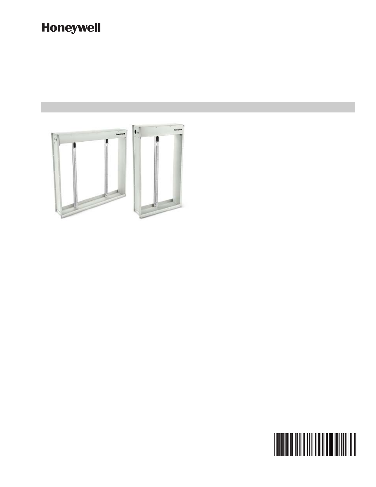
HUVF SERIES DUCT MOUNTED UV SYSTEM
531-00455—01
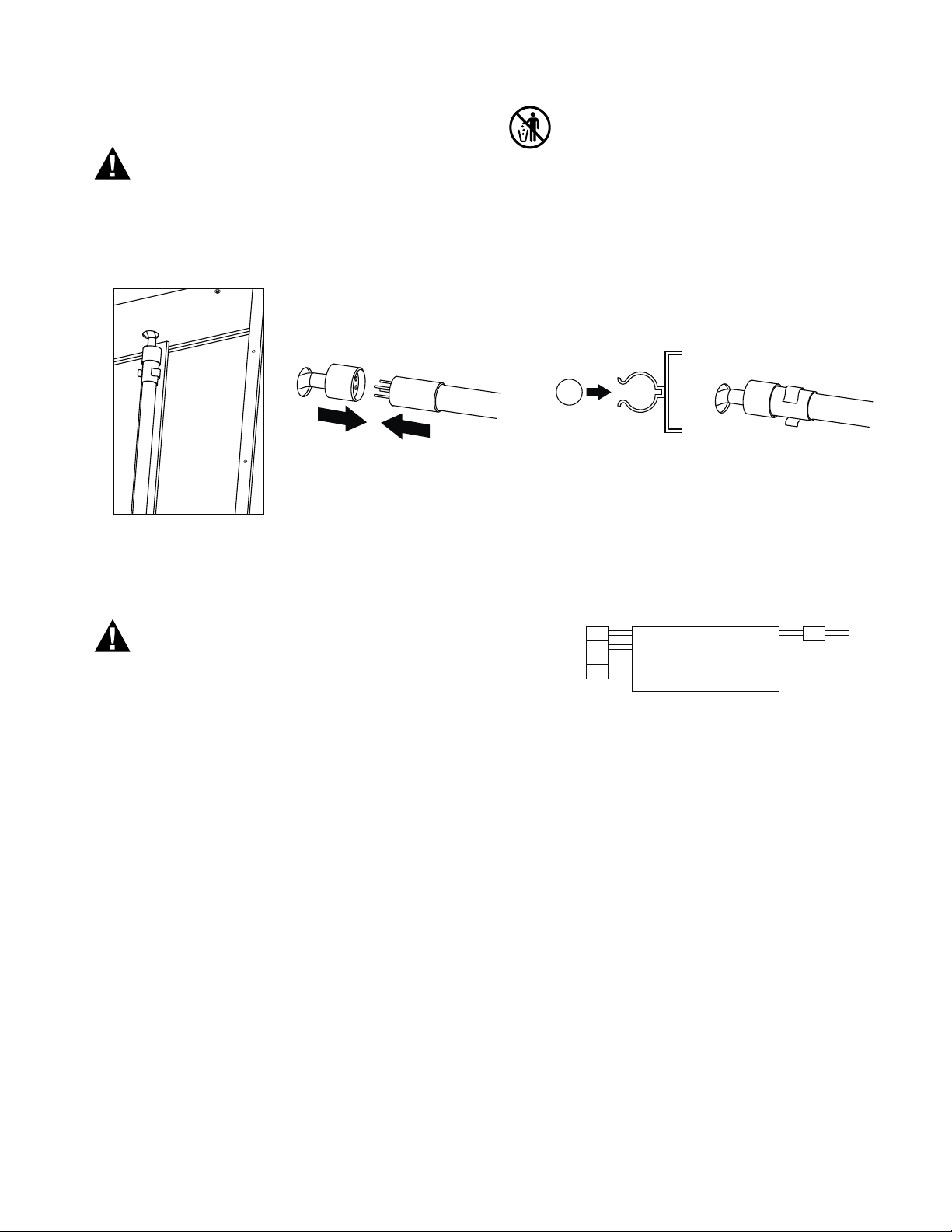
Connect the Lamps
Breakable Glass Hazard.
Can cause personal injury.
Be careful when inserting bulb(s) into lamp base.
Wear protective gloves when handling the bulb(s).
This device contains mercury in the sealed
ultraviolet bulb(s). Do not place your used bulb(s) in
the trash. Dispose of properly.
Make sure that the UV lamp is connected properly to the
4-pin holder and is fixed in the clamps provided on the
reflector as shown in Fig. 7 below.
Fig. 7. Bulb connection.
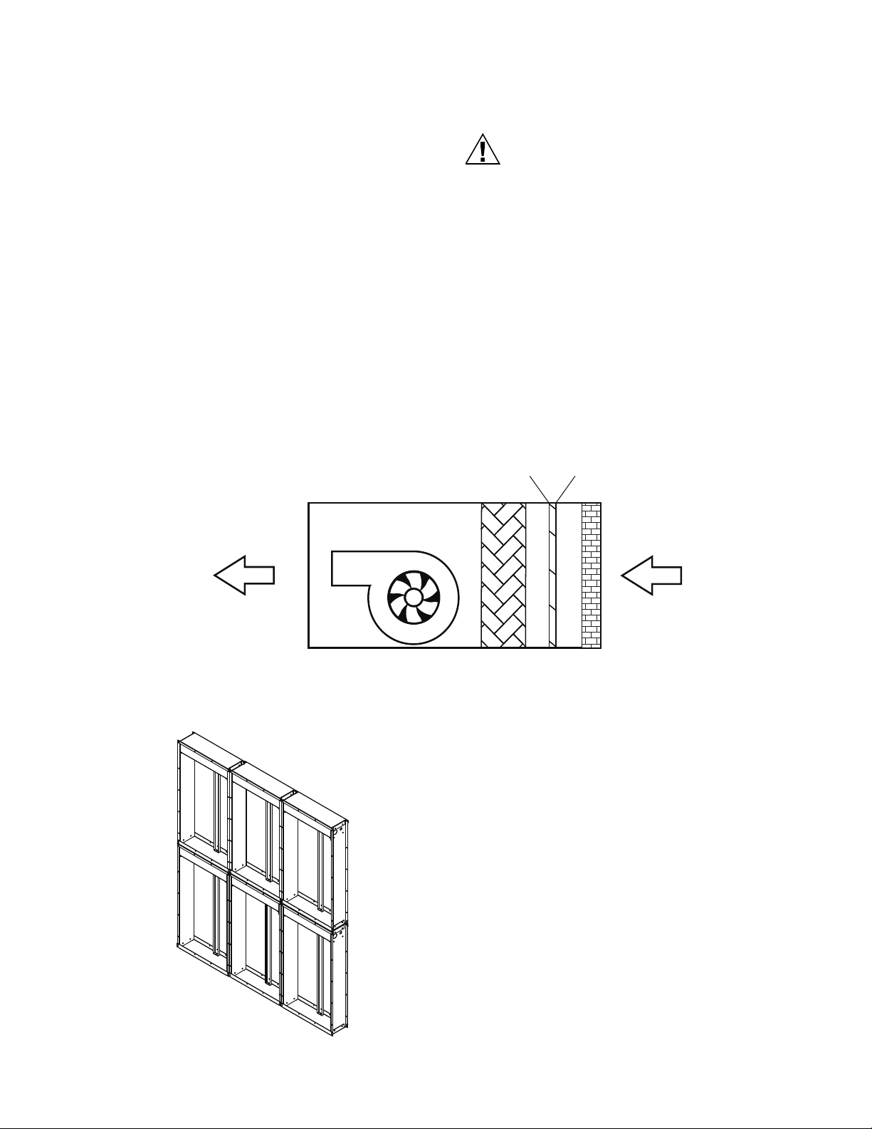
WIRING
Main power supply must be secured with
interlock on the AHU door.
The electrical supply circuit connected to this UV
appliance must be routed through an electrical
interlock switch placed on the HVAC system duct
access panels and doors to prevent accidental UV
exposure when servicing the air ducts or
equipment. Interlock shall break all supply
conductors.
• Power supply wiring system shall provide a
disconnect switch for all poles.
• Assure all wiring complies with local codes and
ordinances.
• Wire the UV system directly to the correct voltage
and frequency electrical source. See Fig. 8.
• Install extension box, with cover, for all external
plugs and wiring connections.
• This appliance incorporates an earth connection
for functional purposes only.
Power Connections
1. Decide which end of the installed array is most acces-
sible for wiring.
2. Cut off the plastic connector for each row of air
cleaners on the end selected.
3. Install a extension box to the end of each row of air
cleaners.
4. Connect power and ground leads to each row of air
cleaners.
5. Install cover on each box.
6. Install box and cover over power connector on oppo-
site end of each row.
Fig. 8. Power connection to HUVF.
OPERATION AND
MAINTENANCE
NOTICE:
• Service of the product to be done by authorized
representative only
• Operated and serviced by qualified personnel
• No interlocks under any circumstance are defeated
• All safety measures recommended are followed as
prescribed
• Provided all control measures are implemented at the
user site for safety as per the Risk analysis document.
• Any internal part of the assembly shall not be removed
for independent use for other applications.
During normal operation make sure that the electrical
supply circuit connected to this UV appliance must be
routed through an electrical interlock switch placed on the
HVAC system duct access panels and doors to prevent
accidental UV exposure when servicing the air ducts or
equipment” or equivalent. “Interlock shall break all supply
conductors.
Power Input
Adjacent System F
MM
M = Male Connector
F = Female Connector
Adjacent
System
HUVF58C1000 / HUVF58C2000
HUVF58S1000 / HUVF58S2000