L
Disconnect power supply before beginning wiring
to prevent electrical shockorequipment damage.
If a new gas control is to be installed, turn off gas
supply before starting installation. Conduct Gas
Leak Test according to gas control manufac-
turer’s instructions after the gas control is in-
stalled.
lf module must be mounted near moisture or
water, provide suitable waterproof enclosure.
PERFORM PREINSTALLATION SAFETY INSPECTION
Ifthis is a replacement installation, check the appliance
and venting system carefully before installing new module.
If a condition which could result in unsafe operation is
detected, the appliance should be shut off and the owner
advised of the unsafe condition. Any potentially unsafe
condition must be corrected before proceeding with the
installation.
MAINTENANCE REQUIREMENTS IN SEVERE ENVI-
RONMENTS
Regular preventive maintenance is important in any ap-
plication, but especially so in agricultural and industrial
applications because
l In many such applications, the equipment operates
1OO,OOO-200,000 cycles per year. Such heavy cy-
cling can wearoutthegascontrolinonetotwoyears.
A normal forced air furnace, for which the controls
were originally intended, typically operates less than
20,000 cycles per year.
l Exposure to water, dirt, chemicals, and heat can
damage the module or the gas control and shut
down the control system. A NEMA 4 enclosure can
reduce exposure to environmental contaminants.
See Electronic Ignition Service Manual, form 70-
6604.
The maintenance program should include regular
checkout of the system as outlined under Checkout, page
11.
FIRE OR EXPLOSION HAZARD
MAY CAUSE PROPERTY DAMAGE, SEVERE
INJURY OR DEATH
Do not attempt to take the module apart or to
clean it. Improper reassembly and cleaning may
cause unreliable operation.
1
Maintenance frequency must be determined individu-
ally for each application. Some considerations are:
l Cycling frequency. Appliances that may cycle more
than 20,000 times annually should be checked
monthly.
l Intermittent use. Appliances that are used season-
ally should be checked before shutdown and again
before the next use.
9 Consequence of unexpected shutdown. Where the
cost of an unexpected shutdown would be high, the
system should be checked more often.
l Dusty, wet, or corrosive environment. Since these
environments can cause the controls to deteriorate
more rapidly, the system should be checked more
often. Protective enclosures, as outlined under
“Planning the Installation”, are recommended re-
gardless of checkout frequency.
Any control should be replaced if it does not perform
properly on checkout or troubleshooting. In addition, re-
place any module if it is wet or looks like it has ever been
wet.
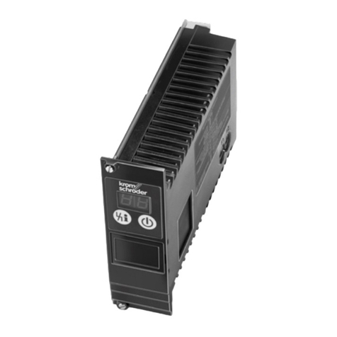
MOUNT IGNITION MODULE
Select a location close enough to the burner to allow a
short, direct cable route to the igniter. Ambient tempera-
ture at the module must be within the range of minus 40”
F to plus 175” F [minus 40” C to plus 79” C]. The module
must be protected from water, moisture, corrosive chemi-
cals and excessive dust and grease.
The module can be mounted in any position. Fasten
securely with four No. 6-32 machine or No. 8 sheetmetal
screws 1 in. [25 mm] long.
MOUNT THE SYSTEM CONTROLS
Mount any required controls, such as the gas control,
hot surface igniter, flame sensor, thermostat, limit and
transformer according to manufacturer’s instructions.
1. Check the wiring diagram furnished by the appli-
ance manufacturer, if available, for circuits differ-
ing from the wiring hookups shown. Carefully
follow any special instructions affecting the gen-
eral procedures outlined below.
2. Disconnect the power supply before making wir-
ing connections to prevent electrical shock or
equipment damage.
I I
IMPORTANT
1. All wiring must comply with applicable electrical
codes and ordinances.
2. When installing the hot surface igniter, the lead-
wires should be kept as short as possible and
should not be allowed to rest against grounded
metal surfaces.
3. A common ground is required for the S89/S890
and the main burner. The 24 V (GND) terminal
internally grounds one side of the transformer.
Any auxiliary controls or limits must not be in the
grounded leg. In addition, the appliance should
be earth-grounded.
4. Make sure thetransformer has adequate VA. The
ignition module requires at least 0.2 A at 24 Vat.
Add the current draws of all other devices in the
control circuit, including the gas control, and
multiply by 24 to determine the total VA require-
ment of these components. Add this total to 4.8
VA (forthe ignition module). The result isthe mini-
mum transformer VA rating. Use a Class IItrans-
former if replacement is required.
5. Check that Ll (hot) and L2 (neutral) are wired to
the proper terminals. If Ll and L2 are inter-
changed, the S89/S890 will not detect the flame,
and will go into safety shutdown.
Connect Igniter
Prepare wiring harness. See Igniter wiring, page 3.
1. On models with quick connects, use insulated 114in.
female quick connects to connect the wiring harness leads
to the HSI terminals on the ignition module.
2. On models with leadwires, use solderlessconnectors
to connect the wiring harness leads to the blue leads from
the module.
3. Connect the wiring harness to the igniter.
5 68-007&l
