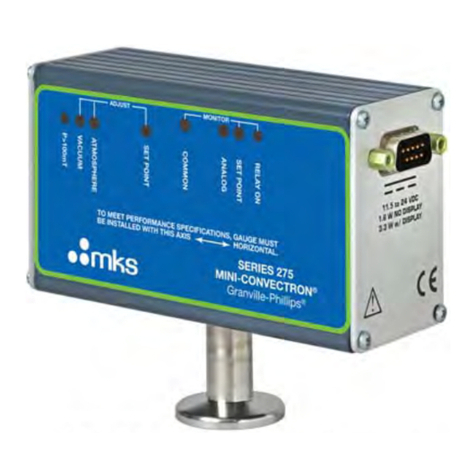
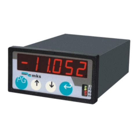
MKS Granville-Phillips Series 275 User manual

Series275
Mini-Convectron®Module with RS-485
and
Dual Process Relays
Instruction Manual
Instruction manual part number 275547
Revision C –December 2021


Series275
Mini-Convectron®Module with RS-485 and
Dual Process Relays
This Instruction Manual is for use with MKS Series 275
Mini-Convectron Modules with RS-485 and dual process
relays. A list of applicable catalog numbers is provided on
the following page.
Customer Service / Technical Support:
MKS Global Headquarters
2 Tech Drive, Suite 201
Andover MA, 01810 USA
Phone: +1-833-986-1686
Visit our website at www.mksinst.com
Instruction Manual
© 2021 MKS Instruments, Inc. All rights reserved.
Granville-Phillips® andConvectron® are registered trademarks, and mksinstTM isa
trademark of MKS Instruments, Inc. All other trademarks and registered trademarks
are the properties of their respective owners.

Series 275 Mini-Convectron®Module with RS-
485 and Dual Process Relays
Catalog numbers for Series 275 Mini-Convectron Modules
This manual is for use only with the following catalog numbers:
275410 - 2 - X X- X
Sensor Type
Gold-Plated Tungsten. . . . . . . . . . . . . . . . . . . . . G
Platinum . . . . . . . . . . . . . . . . . . . . . . . . . . . . . . . . .P
Flange/Fitting
NW16KF flange. . . . . . . . . . . . . . . . . . . . . . . . . . .D
NW25KF flange. . . . . . . . . . . . . . . . . . . . . . . . . . .E
2.75 inch (NW35CF) ConFlat. . . . . . . . . . . . . . . .G
1/8 NPT / 1/2 inch tubulation . . . . . . . . . . . . . .P
1/4 inch VCR-type female fitting . . . . . . . . . . . Q
1/2 inch VCR-type female fitting . . . . . . . . . . . .R
Measurement Units
Torr . . . . . . . . . . . . . . . . . . . . . . . . . . . . . . . . . . . . . T
Pascal . . . . . . . . . . . . . . . . . . . . . . . . . . . . . . . . . . . .P
NOTE:
Customer specific products may have a five-digit number following the catalog
numbers shown above.
Example: 275410-2-GD-T-XXXXX, where -XXXXX represents a configuration
outside of the standard catalog number.

5
Mini-Convectron Module with RS-485 and Dual Process Relays
Instruction Manual - 275547
Table of Contents
Chapter 1
Safety
. .
. . . .
. . . .
. . . .
. . . . . . . . . . . . . . . . . . . . . . . . . . . . . . . . . . .
7
Chapter 2 Introduction.............................................................................................15
2.1
Introduction......................................................... 15
2.2
Gauge Tube Construction.........................................................................16
2.3
Specification............................................................................................17
2.4
Receiving Inspection............................................................................17
Domestic Shipments............................................................................17
2.5
International Shipments ............................................................................18
2.6
Damaged Material .......................................................................................18
Chapter 3 Installation
.................................................................................................... 19
3.1
Important Precautions for Mini-Convectron Installation. ...........19
3.2
Install Pressure Relief Devices.................................................................20
3.3
Installation Procedure.................................................................................21
3.4
Locate and Orient the Module ...............................................................21
Locate the Module.......................................................................................21
Orient the Module .......................................................................................22
3.5 Attach the Module to the Vacuum Chamber ...................................23
Gauge Mounts...............................................................................................24
3.6 I/O Connector Wiring .................................................................................25
3.7 Grounding .......................................................................................................26
3.8 RS-485 Network Wiring.............................................................................27
Configure the setpoint relays for the application...........................27
Chapter 4 Operation .................................................................................................29
4.1 Power Requirement.....................................................................................29
4.2
Front Panel Features ...................................................................................29
4.3
Digital Communications.....................................................................29
4.4
Syntax/Address Overview..................................................................30
RS-485 Address Switch Settings .....................................................30
Baud Rate, Stop Bit and Parity................................................................30
RS-485 Command Set ................................................................................31
Command –Response Timing................................................................38
Input Voltage Error......................................................................................38
RX, TX Timing.................................................................................................38
Chapter 5 Calibration
.................................................................................................... 39
5.1 Calibration.......................................................................................................39
Vacuum Adjust ..............................................................................................39
Atmosphere Adjust......................................................................................39
5.2 Use with Gases Other Than N2and Air ...............................................40

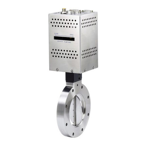
Table of Contents
Chapter 6 Maintenance............................................................................................45
6.1 General Information ....................................................................................45
Damage Requiring Service .......................................................................45
6.2 Troubleshooting ...........................................................................................46
Precautions......................................................................................................46
6.3 Symptoms and Possible Causes.............................................................47
6.4 Convectron Gauge Removal and Replacement...............................48
Removing the Convectron Gauge.........................................................48
Replacing the Convectron Gauge..........................................................48
6.5 Convectron Gauge Test .............................................................................49
Mini-Convectron Module with RS-485 and Dual Process Relays
Instruction Manual - 275547
6

7
Mini-Convectron Module with RS-485 and Dual Process Relays
Instruction Manual - 275547
Chapter 1 Safety
1.1 Safety Introduction
START BY READING THESE IMPORTANT SAFETY INSTRUCTIONS AND NOTES
collected here
for your convenience and repeated with additional information at appropriate points throughout this
instruction manual.
These safety alert symbols in this manual or on the Product mean caution - personal safety, property
damage or danger from electric shock. Read these instructions carefully.
Danger indicates a hazardous situation which, if not
avoided, will result in death or serious injury.
Warning indicates a hazardous situation which, if not
avoided, could result in death or serious injury.
Caution indicates a hazardous situation or unsafe
practice which, if not avoided, may result in minor or
moderate personal injury.
Indicates a situation or unsafe practice which, if not
avoided, may result in equipment damage.
This product was designed and tested to offer reasonably safe service provided it is installed,
operated, and serviced in strict accordance with these safety instructions.
These instructions do not and cannot provide for every contingency that may
arise in connection with the installation, operation, or maintenance of this
product. If you require further assistance, contact MKS.
Notice
Safety Precautions
Failure to comply with these instructions may result in serious
personal injury, including death, or property damage.
Always observe and follow all safety notices that are provided
throughout this instruction manual and on the product.

8
Mini-Convectron Module with RS-485 and Dual
Process Relays
Instruction Manual - 275547
Chapter 1
These safety precautions must be observed during all phases of operation, installation, and service of
this product. Failure to comply with these precautions or with specific warnings elsewhere in this
manual violates safety standards of design, manufacture, and intended use of the instrument. MKS
Instruments, Inc. disclaims all liability for the customer's failure to comply with these requirements.
•Read Instructions –Read all safety and operating instructions before operating the product.
•Retain Instructions –Retain the Safety and Operating Instructions for future reference.
•Heed Warnings –Adhere to all warnings on the product and in the operating instructions.
•Follow Instructions –Follow all operating and maintenance instructions.
•Accessories –Do not use accessories not recommended in this manual as they may be hazardous.
Electrical Shock or Personal Injury
The service and repair information in this manual is for the use
of Qualified Service Personnel. To avoid possible electrical
shock or personal injury, do not perform any procedures in
this manual or perform any servicing on this product unless
you are qualified to do so.
Electrical Shock or Fire
To reduce the risk of fire or electric shock, do not expose this
product to rain or moisture.
Objects and Liquid Entry - Never push objects of any kind into
this product through openings as they may touch dangerous
voltage points or short out parts that could result in a fire or
electric shock. Be careful not to spill liquid of any kind onto
the products.

Safety
9
Mini-Convectron Module with RS-485 and Dual Process Relays
Instruction Manual - 275547
1.2 Grounding Requirements
See Grounding, Section 3.7 in the Installation chapter for more detailed requirements regarding
gauge and system grounding.
1.3 High Voltage
The Mini-Convectron Module does not have higher voltages than the source voltage required for
operation of the module.
However, hazardous voltages may be present in the vacuum system.
Proper Grounding
All components of a vacuum system used with this or any similar
high voltage product must be maintained at Earth ground for safe
operation.
Be aware that grounding this product does not guarantee that
other components of the vacuum system are maintained at Earth
ground.
Verify that the vacuum port to which the Series 275 Module is
mounted is electrically grounded. It is essential for personnel safety
as well as proper operation that the envelope of the gauge be
connected to a facility ground. See Section 3.7 for detailed
grounding instructions.
Connect power cords only to properly grounded outlets or sources.
High Voltage
Be aware that when high voltage is present in any vacuum system,
a life threatening electrical shock hazard may exist unless all
exposed conductors are maintained at Earth ground.
All conductors in, on, or around the vacuum system that are
exposed to potential high voltage electrical discharges must either
be shielded at all times to protect personnel or must be connected
to Earth ground at all times.
This hazard is not unique to this product.
High Voltage
Be aware that an electrical discharge through a gas may couple
dangerous high voltage directly to an ungrounded conductor
almost as effectively as would a copper wire connection. A person
may be seriously injured or even killed by merely touching an
exposed ungrounded conductor at high potential.
This hazard is not unique to this product.

Chapter 1
10
Mini-Convectron Module with RS-485 and Dual Process Relays
Instruction Manual - 275547
1.4 Over-Pressure Conditions
Install suitable devices that will limit the pressure from external gas sources to the level that the
vacuum system can safely withstand. In addition, install suitable pressure relief valves or rupture disks
that will release pressure at a level considerably below that pressure which the system can safely
withstand. Suppliers of pressure relief valves and pressure relief disks can be located via an on-line
search. Confirm that these safety devices are properly installed before installing the product.
Ensure the following precautions are complied with at all times:
(1)
the proper gas cylinders areinstalled
(2)
the gas cylinder valve positions are correct on manual systems
(3)
the automation is correct on automated gas delivery systems
Vacuum gauges with compression fittings may be forcefully ejected if the vacuum system is
pressurized.
Over-Pressure Conditions
Install suitable devices that will limit the pressure to the level
the vacuum system can safely withstand. In addition, install
suitable pressure relief valves or rupture disks that will
release pressure at a level considerably below the pressure
that the system can safely withstand.
Potential Automatic Operation
It is the installer's responsibility to ensure that the automatic
signals provided by the product are always used in a safe
manner. Carefully check the system programming before
switching to automatic operation.

Safety
11
Mini-Convectron Module with RS-485 and Dual Process Relays
Instruction Manual - 275547
1.5 System and Environment
1.6 Responsibility
It is the responsibility of the Customer to comply with all local, state, and federal ordinances,
regulations, and laws applicable to the installation, operation and service of this equipment.
It is the responsibility of the end user to provide sufficient lighting at work to meet local regulations.
Operation and Service of this equipment in strict accordance with the methods and procedures
supplied by MKS is the responsibility of the Customer.
MKS Instruments, Inc. assumes no liability, whatsoever, for any personal injuries or damages resulting
from the operation or service of this equipment in any manner inconsistent or contrary to the
methods supplied in MKS literature including, but not limited to, manuals, instructions, bulletins,
communications, and recommendations.
For product safety related matters, contact the MKS Customer Service Department. See Section 1.8
for detailed information regarding how to contact MKS Customer Service Representatives.
Explosive Environment
Do not use the Series 275 Module in an environment of
explosive or combustible gases or gas mixtures. Operation of
any electrical instrument in such an environment constitutes a
definite safety hazard. Do not use the product to measure the
pressure of explosive gases or gas mixtures.
Potential Automatic Operation
It is the installer's responsibility to ensure that the automatic
signals provided by the product are always used in a safe
manner. Carefully check the system programming before
switching to automatic operation.
Vacuum Chamber High Pressures
Where an equipment malfunction could cause a hazardous
situation, always provide for fail-safe operation. As an
example, in an automatic backfill operation where a
malfunction might cause high internal pressures, provide an
appropriate pressure relief device.

Chapter 1
12
Mini-Convectron Module with RS-485 and Dual Process Relays
Instruction Manual - 275547
1.7 Damage Requiring Service
Disconnect the product from all power sources and refer servicing to Qualified Service Personnel
under the following conditions:
a. When any cable or plug is damaged.
b. If any liquid has been spilled onto, or objects have fallen into the product.
c. If the product has been exposed to rain or water.
d. If the product does not operate normally even if you follow the operating instructions. Adjust
only those controls that are covered by the operation instructions. Improper adjustment of
other controls may result in damage and will often require extensive work by a qualified
technician to restore the product to its normal operation.
e. If the product has been dropped or the enclosure has been damaged.
f. When the product exhibits a distinct change in performance. This indicates a need for service.
1.8 Service Guidelines
Some minor problems are readily corrected on site. If the product requires service, contact the MKS
Technical Support Department at +1-833-986-1686. If the product must be returned to the factory
for service, request a Return Material Authorization (RMA) from MKS. Do not return products without
first obtaining an RMA. In some cases a hazardous materials disclosure form may be required. The
MKS Customer Service Representative will advise you if the hazardous materials document is
required.
When returning products to MKS, be sure to package the products to prevent shipping damage.
Shipping damage on returned products as a result of inadequate packaging is the Buyer's
responsibility.
For Customer Service / Technical Support:
MKS Global Headquarters
2 Tech Drive, Suite 201
Andover MA, 01810 USA
Phone: +1-833-986-1686
Email: insidesales@mksinst.com
Visit our website at www.mksinst.com
Do not substitute parts or modify the instrument.
Because of the danger of introducing additional hazards, do not install
substitute parts or perform any unauthorized modification to the product.
Return the product to a service facility designated by MKS for service and
repair to ensure that safety features are maintained. Do not use this product
if it has unauthorized modifications.
Notice
Safety Check - Upon completion of any service or repairs to this product, ask
the Qualified Service Person to perform safety checks to determine that the
product is in safe operating order.
Notice

Safety
13
Mini-Convectron Module with RS-485 and Dual Process Relays
Instruction Manual - 275547
1.9 Warranty Information
MKS Instruments, Inc. provides an eighteen (18) month warranty from the date of shipment for new
products. The MKS Instruments, Inc. General Terms and Conditions of Sale provides the complete
and exclusive warranty for MKS products. This document may be located on the MKS web site at
www.mksinst.com, or may be obtained by contacting a MKS Customer Service Representative.
1.10 FCC Verification
This equipment was tested and found to comply with the limits for a Class A digital device, pursuant
to Part 15 of the FCC Rules. These limits are designed to provide reasonable protection against
harmful interference when the equipment is operated in a commercial environment. This equipment
generates, uses, and can radiate radio frequency energy and, if not installed and used in accordance
with this instruction manual, may cause harmful interference to radio communications. However,
there is no guarantee that interference will not occur in a particular installation. Operation of this
equipment in a residential area may cause harmful interference in which case the user will be
required to correct the interference at his own expense. If this equipment does cause harmful
interference to radio or television reception, which can be determined by turning the equipment off
and on, the user is encouraged to try to correct the interference by one or more of the following
measures:
•Reorient or relocate the receiving antenna.
•Increase the separation between the equipment and the receiver.
•Connect the equipment into an outlet on a circuit different from that to which the receiver is
connected.
•Consult the dealer or an experienced radio or television technician for help.

Chapter 1
14
Mini-Convectron Module with RS-485 and Dual Process Relays
Instruction Manual - 275547

15
Mini-Convectron Module with RS-485 and Dual Process Relays
Instruction Manual - 275547
Chapter 2 Introduction
2.1 Introduction
Unlike traditional thermocouple and Pirani gauges, Convectron gauges take advantage of heat loss
due to convection cooling at higher pressures. This extends the range of accurate, repeatable vacuum
measurements to atmosphere.
The Mini-Convectron module is a self-contained measurement device incorporating Convectron
gauge technology and electronics in a compact modular design. The electronics and gauge are
packaged in an all-metal package that provides a rugged enclosure and a high level of immunity to
electrical noise. The Convectron gauge used in the module is field-replaceable.
The Mini-Convectron module is available in a variety of output configurations. This instruction manual
is for use with a Mini-Convectron module with RS-485 output and dual process control relays. These
adjustable setpoints allow control of valves, switches, alarm signals, or other controls.
Figure 2-1 Series 275 Mini-Convectron Module with RS-485 and Dual Process Relays

16
Mini-Convectron Module with RS-485 and Dual Process Relays
Instruction Manual - 275547
Chapter 2
2.2 Gauge Tube Construction
The transducer is a convection enhanced Pirani gauge providing rapid response, six-decades of
pressure transduction, stable calibration, and good accuracy. The Pirani sensing element, R1 of the
schematic of Figure 2-2, is one leg of a Wheatstone Bridge. A temperature compensating network, R2,
forms the second leg of the bridge. The temperature sensitive component of this network is mounted
inside the gauge tube envelope with the sensor. All other resistors of the bridge are mounted upon
the exterior electrical feedthrough pins of the gauge tube. Pin 4 serves as an electrical terminal for
construction of the compensating network, R2, but no connection is made therefrom to the controller.
All materials have been chosen for ultra-high vacuum service, corrosion resistance and bakeability to
150 °C. The gauge tube envelope is type 304 stainless steel. All metallic joints in the envelope are
welded. No solder is used within the envelope. The following materials are exposed to the vacuum:
Type 304 stainless steel, Carpenter Alloy 52, Kovar, Kapton®, gold plated tungsten and borosilicate
glass.
Figure 2-2 Gauge Tube Schematic
PIN 1
PIN5
PIN2
PIN3

17
Mini-Convectron Module with RS-485 and Dual Process Relays
Instruction Manual - 275547
Introduction
2.3 Specifications
Table 2-1 Specifications for the Mini-Convectron Module
Function
Description
Measuring range for N2
• 1 x 10⁻⁴ to 1000 Torr
Operation in the range of 1x10⁻⁴ to 1x10⁻³ Torr will require periodic
verification of the zero by reducing system pressure to below
1x 10⁻⁵ Torr
• 1 x 10⁻⁴ to 1.300 mBar
•
1.0–2 to 130 KPa
Ambient operating temperature range
0 to +40 °C
Bakeout temperature range
(non-operating)
85 °C max.
Digital interface
RS–485, (2 wire)
Baud rate
300, 600, 1200, 2400, 4800, 9600, 19200 (default),
38400,57600, 115200
Data format
7 bits, even parity, 1 stop bit or 7 bits, odd parity, 1 stop bit or 8 bits, no
parity, 1 stopbit.
Power required
• +11.5 Vdc to 26.5 Vdc at 0.12 A
•
Protected against reversals, transients or over-voltages
•
1.5 watts maximum
CE Compliance
EMC
EN61326-1
Safety
EN61010-1
IP rating
IP20
Gauge tube internal volume
40 cc (2.5 cu in.)
Sensor wire
Gold plated tungsten
Setpoints (two)
•
Single pole, double throw relay, silver alloy - gold clad contacts
•
UL rating: 1 A at 30Vdc
Setpoint factory default
Disabled - set at 999 Torr
Connector
Input power, computer interface, and setpoints - 15 pin D male
Package
•
Aluminum extrusion design with aluminum end plates
•
4.5” long x 1.7” wide x 2.5” high plus gauge port and fitting
2.4 Receiving Inspection
2.4.1 Domestic Shipments
Inspect all material received for shipping damage.
Confirm that the shipment includes all material and options ordered. If materials are missing or
damaged, the carrier that made the delivery must be notified within 15 days of delivery in accordance
with Interstate Commerce regulations to file a valid claim with the carrier. Any damaged material
including all containers and packing should be held for carrier inspection. Contact the MKS Customer
Service Department if the shipment is not correct for reasons other than shipping damage.

Chapter 2
18
Mini-Convectron Module with RS-485 and Dual Process Relays
Instruction Manual - 275547
2.5 International Shipments
Inspect all material received for shipping damage. Confirm that the shipment includes all material and
options ordered. If items are missing or damaged the carrier making delivery to the customs broker
must be notified within 15 days of delivery.
If an airfreight forwarder handles the shipment and their agent delivers the shipment to customs the
claim must be filed with the airfreight forwarder.
If an airfreight forwarder delivers the shipment to a specific airline and the airline delivers the
shipment to customs the claim must be filed with the airline, not the freight forwarder.
2.6 Damaged Material
Any damaged material, including all containers and packaging, should be held for carrier inspection.
Contact the MKS Customer Service Department if the shipment is not correct for reasons other than
shipping damage.

19
Mini-Convectron Module with RS-485 and Dual Process Relays
Instruction Manual - 275547
Chapter 3 Installation
3.1 Important Precautions for Mini-Convectron Installation
The following precautions in the use and installation of the Mini-Convectron must be observed.
•It is recommended that the Mini-Convectron be installed with the port oriented vertically
downward to ensure that no system condensates or other liquids collect in the gauge tube. The
gauge tube axis must be horizontal if it is to be used at pressures above 1 Torr. Although the
gauge tube will read correctly below 1 Torr when mounted in any position, erroneous readings
will result at pressures above 1 Torr if the tube axis is not horizontal.
•Do not use a compression mount (quick connect) for attaching the Mini-Convectron to the
system in applications resulting in positive pressures in the gauge tube. Positive pressures may
blow the gauge tube out of a compression fitting and damage equipment and injure personnel.
Pipe thread or flange mounting systems should be used for positive pressure applications. In
any case, the absolute pressure in the tube should not exceed 1000 Torr.
•Do not perform electrical continuity tests on the Mini-Convectron tube with instruments
applying voltages in excess of 1 volt when the tube is at vacuum, or 5 volts when at atmospheric
pressure. Exceeding these voltages will damage the sensing element.
•Keep the gauge tube clean. Do not remove the mounting port cover until you are ready to
install the Module.
•Do not mount the Mini-Convectron in a manner such that deposition of process vapors, upon
the internal surfaces of the gauge tube, may occur through line-of-sight access to the interior of
the gauge tube.
•Do not install the Mini-Convectron where high amplitudes of vibration are present. Excessive
vibration will cause forced convection at high pressure giving erroneous readings.
•Do not bake the Mini-Convectron at temperatures exceeding 85 °C.
•Do not install the gauge tube where it will be subject to corrosive gases such as mercury vapor
or fluorine which will attack the gold plated sensor.
•For greatest accuracy and repeatability, the Mini-Convectron gauge tube should be located in a
stable room temperature environment.
•All connections to the unit are to be made with shielded cable or cables. The shield or shields
are to be connected to the connector shell.
Explosive Environment
Using the Mini-Convectron module to measure the pressure
of flammable or explosive gases can cause a fire or explosion
resulting in severe property damage or personal injury.
Do not use the module to measure the pressure of flammable
or explosive gases.

Chapter 3
20
Mini-Convectron Module with RS-485 and Dual Process Relays
Instruction Manual - 275547
Figure 3-1 Mini-Convectron Module with RS-485
3.2 Install Pressure Relief Devices
Before installing the module, install appropriate pressure relief devices in the vacuum system.
MKS does not supply pressure relief valves or rupture disks. Suppliers of pressure relief valves and
pressure relief disks can be located via an on-line search. Confirm that these safety devices are
properly installed before installing the Mini-Convectron Module.
Over-Pressure Conditions
Operating the module above 1000 Torr (1333 mbar, 133 kPa)
true pressure could cause pressure measurement error or
product failure.
To avoid measurement error or product failure due to over-
pressurization, install pressure relief valves or rupture disks in
the system if pressure exceeds 1000 Torr (1333 mbar, 133
kPa).
Over-Pressure Conditions
Failure to use accurate pressure conversion data for N2 or air
to other gases can cause an explosion due to over-
pressurization.
If the module will measure any gas other than N2 or air,
before putting the module into operation, adjust setpoint
relays for the process gas that will be used.
Other manuals for Granville-Phillips Series 275
3
Table of contents
Other MKS Control Unit manuals

MKS
MKS Series 275 MiniConvectron User manual

MKS
MKS Automated SENTRY 1000 User manual

MKS
MKS HPS 145 Vacuum Sentry Series User manual

MKS
MKS Series 275 MiniConvectron User manual

MKS
MKS 253B-2-2-2 User manual

MKS
MKS 390 Series User manual

MKS
MKS HPS User manual

MKS
MKS Granville-Phillips 203 Series User manual

MKS
MKS HPQ2-IP User manual

MKS
MKS AX Series User manual