Honeywell ST7700 User manual
Other Honeywell Control Unit manuals
Honeywell
Honeywell XLS-REL Product manual

Honeywell
Honeywell VF5000 Series User manual
Honeywell
Honeywell FF-SRS5988 User manual

Honeywell
Honeywell 5496 User manual
Honeywell
Honeywell LCBS Connect User manual

Honeywell
Honeywell Elster Jeavons S100 User manual
Honeywell
Honeywell VQ400 Series User manual
Honeywell
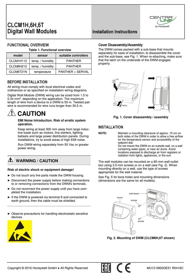
Honeywell CENTRALINE CLCM1H112 User manual
Honeywell
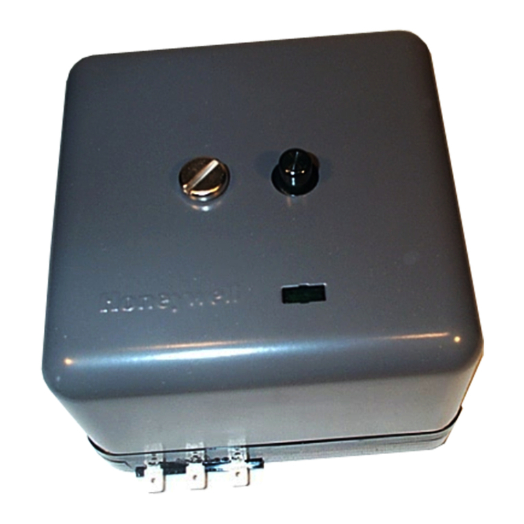
Honeywell RA890F Protectorelay Primary Control Installation guide
Honeywell
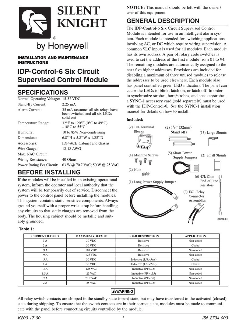
Honeywell SILENT KNIGHT IDP-Control-6 User manual

Honeywell
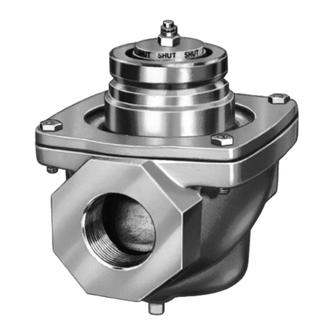
Honeywell TRADELINE VR8345M User manual
Honeywell
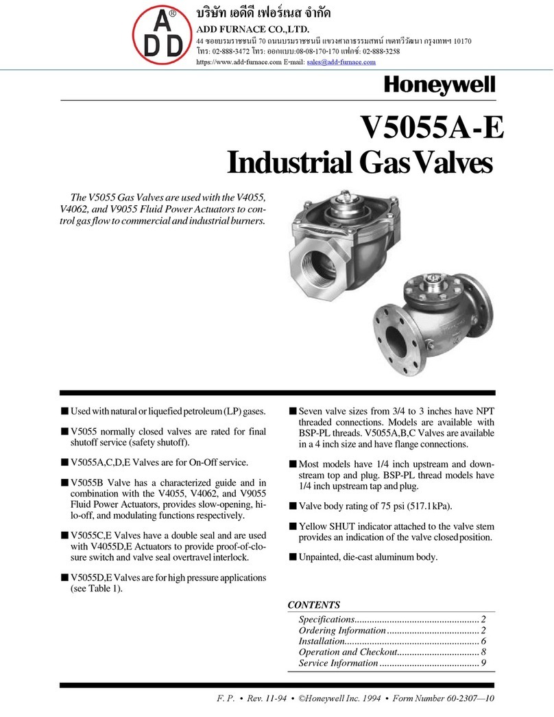
Honeywell V5055A User manual

Honeywell
Honeywell MDC108200 User manual
Honeywell
Honeywell V5055A-E User manual
Honeywell
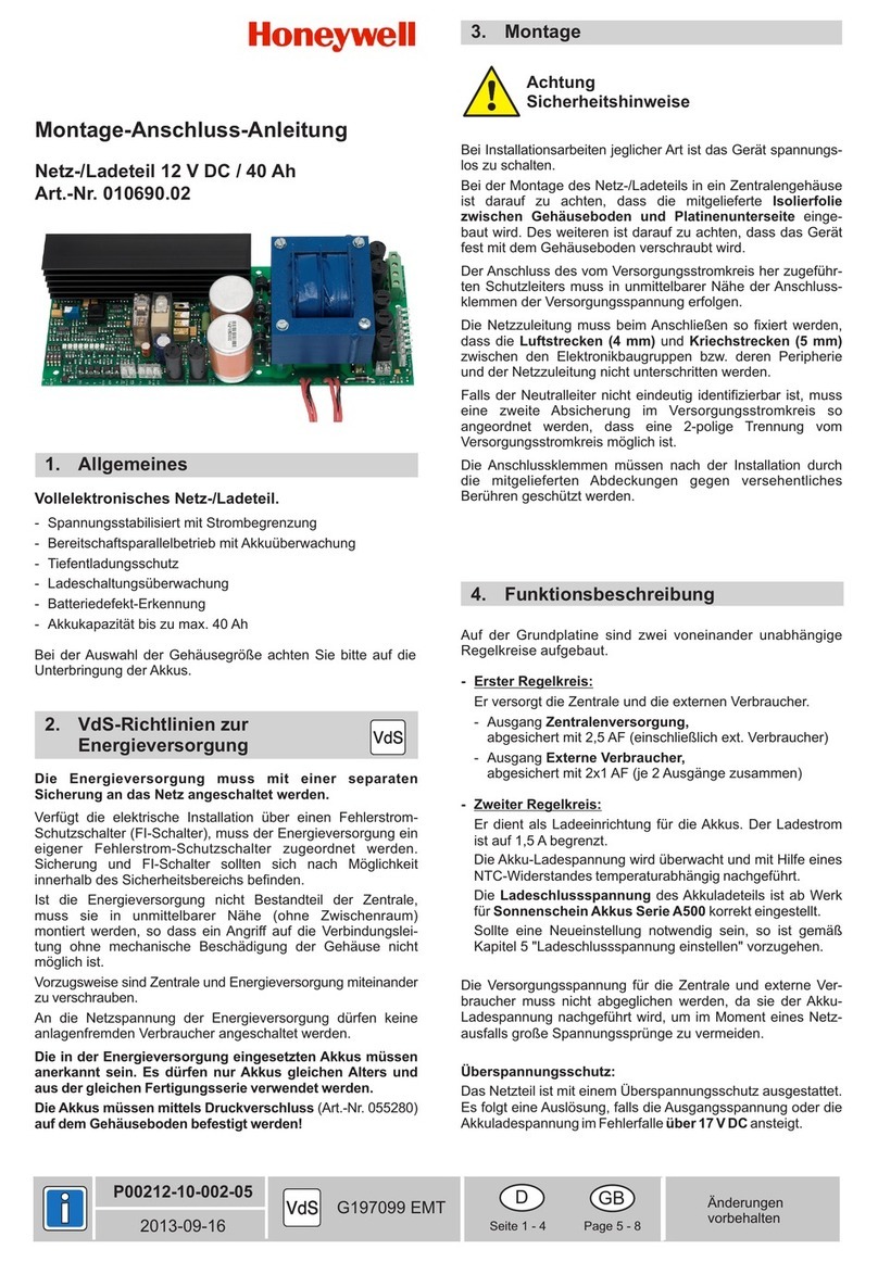
Honeywell 010690.02 Instruction manual
Honeywell
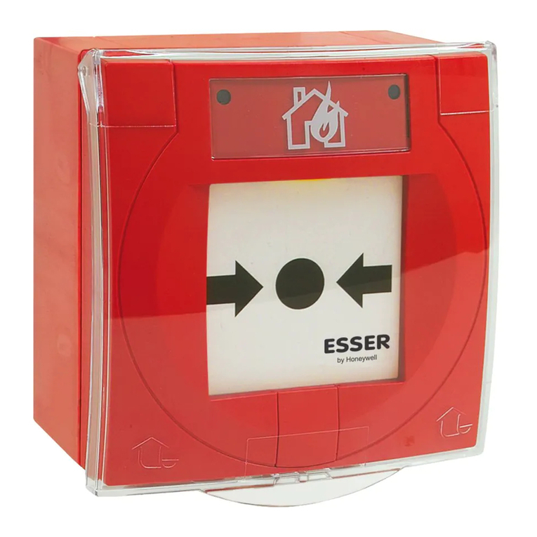
Honeywell ESSER IQ8MCP User manual

Honeywell
Honeywell Aquatrol W964F Owner's manual

Honeywell
Honeywell Ex-Or CDH8U5 Installation and operation manual
Honeywell
Honeywell Centraline FALCON User manual
Honeywell
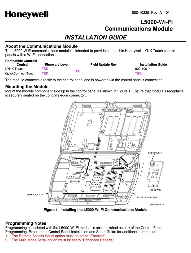
Honeywell L5000-Wi-Fi User manual
Popular Control Unit manuals by other brands

Festo
Festo Compact Performance CP-FB6-E Brief description

Elo TouchSystems
Elo TouchSystems DMS-SA19P-EXTME Quick installation guide

JS Automation
JS Automation MPC3034A user manual

JAUDT
JAUDT SW GII 6406 Series Translation of the original operating instructions

Spektrum
Spektrum Air Module System manual

BOC Edwards
BOC Edwards Q Series instruction manual

KHADAS
KHADAS BT Magic quick start

Etherma
Etherma eNEXHO-IL Assembly and operating instructions

PMFoundations
PMFoundations Attenuverter Assembly guide

GEA
GEA VARIVENT Operating instruction

Walther Systemtechnik
Walther Systemtechnik VMS-05 Assembly instructions

Altronix
Altronix LINQ8PD Installation and programming manual
