10
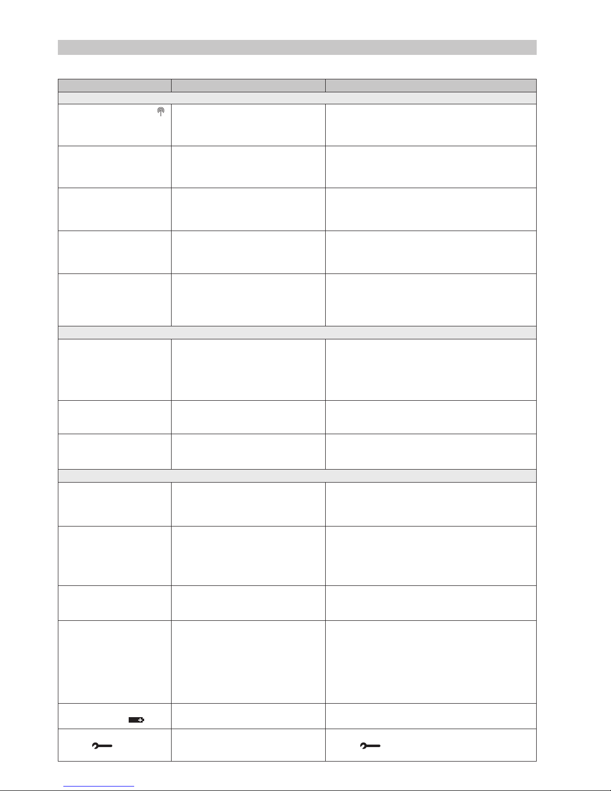
Section 9: Trouble Shooting
Symptom (Fault Message)
After binding procedure the
symbol on HR80UK display
is off.
After binding procedure the red
LED of the HC60NG is on and
the green one is flashing once
every 3 sec.
After binding procedure the red
LED of the HC60NG is on and
green LED is flashing twice
every 3 sec.
After binding procedure the red
LED of the HC60NG is on and
green LED is flashing 3 times
every 3 sec.
After binding procedure the red
LED of the HC60NG is on and
green LED is flashing 4 times
every 3 sec.
HR80UK does not receive
the correct setpoint from the
CM67z.
The boiler does not switch on
when the HR80UK setpoint is
set to ON.
HC60NG’s green LED is not
flashing every 5 sec during the
system test
The red LED of the HC60NG
is on.
The red LED of the HC60NG is
flashing 2.5 sec on/2.5 sec off.
The CM67z shows a different
actual temperature than the
HR80UK setpoint
Blank display on CM67z or
HR80UK.
CM67z display shows a flash-
ing battery symbol ( ).
CM67z displays a spanner
symbol ( ).
Possible Cause
Incorrect or incomplete binding procedure.
Bad position of the CM67z during binding.
Incorrect or incomplete binding procedure.
Bad position of the CM67z during binding.
An attempt was made to bind more than 4
CM67z units to the HC60NG.
An attempt was made to cross bind the
HC60NG with system timing message
when no other binding was present.
An attempt was made to bind two system
timing messages to one HC60NG.
Bad position of the CM67z.
No binding data in the HR80UK.
HR80UK bound to the wrong zone.
Missing binding data in the HC60NG.
Bad position of the CM67z.
The HC60NG receives no messages:
RF signal is blocked (e.g due to bad posi-
tion of the CM67z) or CM67z and HR80UK
batteries are exhausted.
The HC60NG has not received signals
from one (or more) transmitters in the
system but still receives signals from other
transmitters: RF signal is blocked (e.g due
to bad position of the CM67z) or CM67z
and HR80UK batteries are exhausted.
Location of HR80UK and CM67z
No batteries.
Wrong battery orientation.
Improper battery compartment insertion
(CM67z only).
Exhausted batteries.
Batteries need replacing.
Fault in the CM67z room unit.
Remedy
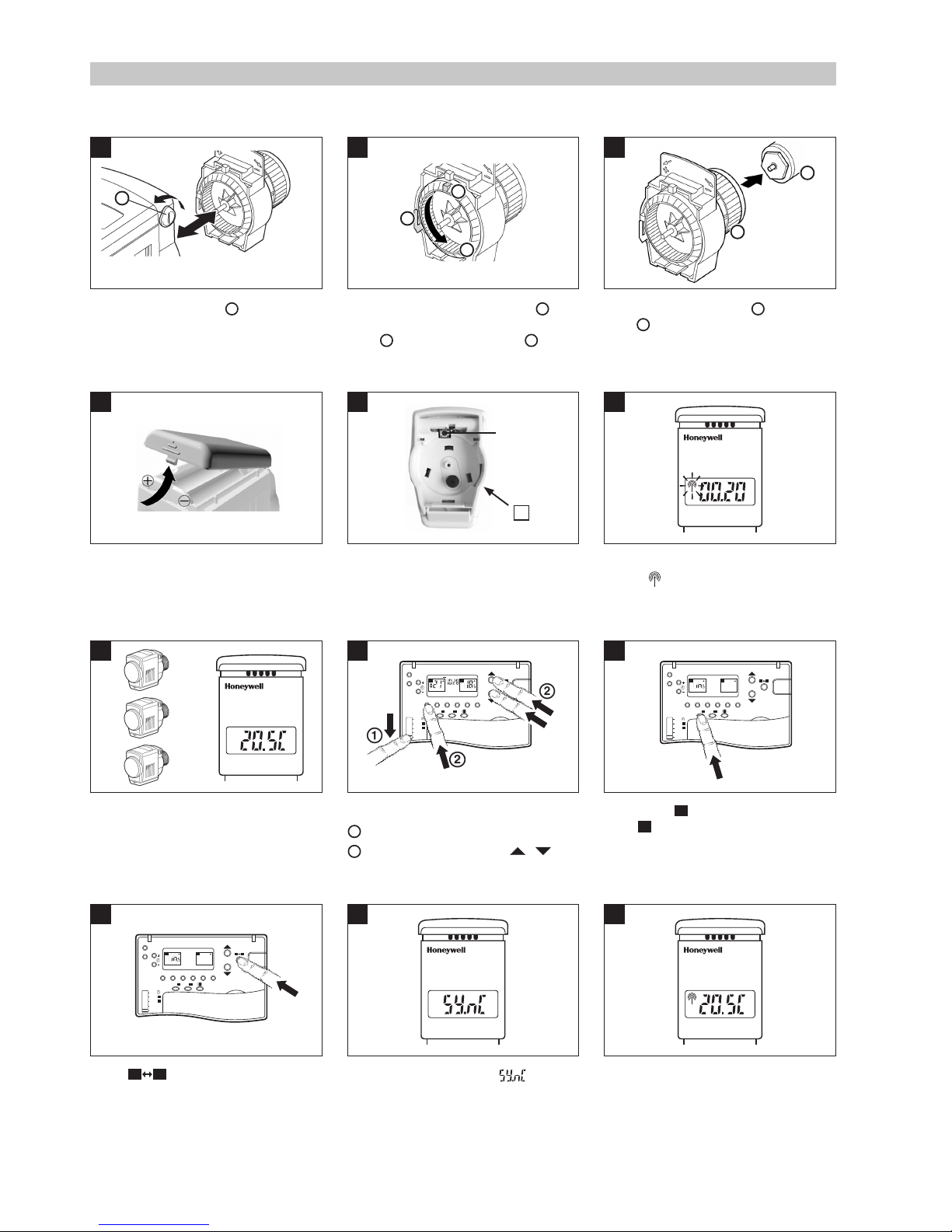
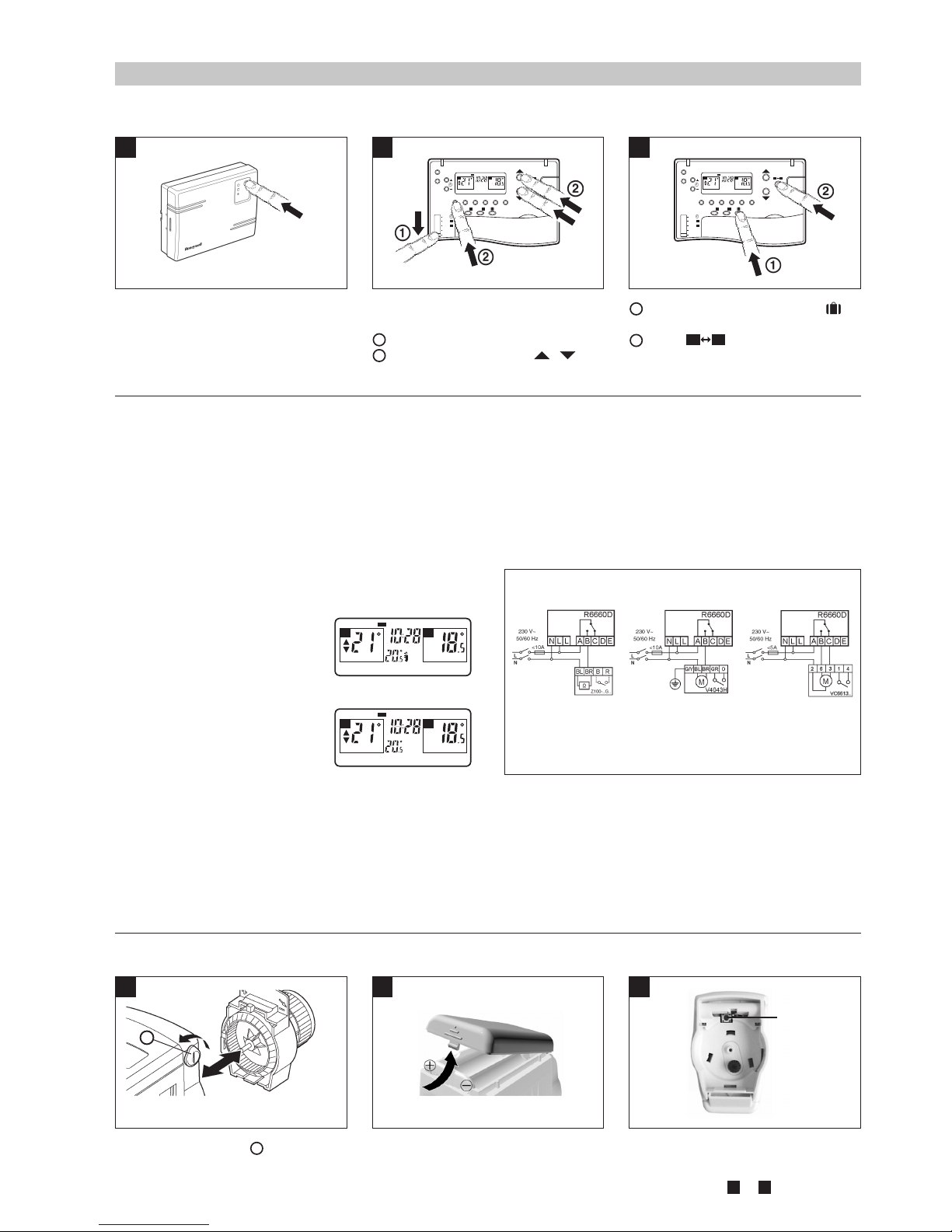
Repeat the binding procedure following the installation instructions.
Repeat the binding procedure keeping approx. 1 m distance
between CM67z and HR80UK.
Repeat the binding procedure following the installation instructions.
Repeat the binding procedure keeping approx. 1 m distance
between CM67z and HC60NG.
Press and hold the HC60NG push button for 15 sec to
reset the memory. Repeat all the binding operations for this
HC60NG making sure that no more than 4 CM67z units are
bound.
Reset the HC60NG binding data by pressing the push button for
15 sec. Repeat the complete start up procedure as described in
Section 8.2: Changing the Configuration.
Make sure that only one CM67z is configured as system
timing master. Reset the HC60NG binding data by press-
ing the push button for 15 sec. Repeat the complete start
up procedure as described in
Section 8.2: Changing the
Configuration
.
Reposition the CM67z and repeat the test.
Repeat the binding procedure.
Repeat the binding procedure, making sure that the HR80UK
is bound to the proper zone.
Repeat the binding procedure (CM67z with the HC60NG
boiler controller or HC60NG zone valve controller).
Reposition the CM67z and repeat the test.
Return the CM67z room unit to the position where communi-
cations is reliable or replace discharged batteries.
Return the CM67z room unit to the position where communi-
cations is reliable or replace discharged batteries.
Link the actual temperature measured by the CM67z with the
HR80UK (only Zone 1 can be configured).
Check that the batteries are in the battery compartment and
that the paper tab (CM67z only) has been pulled out.
Check that the batteries have been installed in the correct orientation.
Remove battery compartment and re-insert.
Replace the batteries.
Replace the batteries.
Remove and re-insert the battery compartment. If the spanner
symbol ( ) does not clear itself in a few minutes call the
Honeywell Technical Help-Desk, details on the back page.
During Binding
During Testing
During Normal Operation
9.1 Trouble Shooting Guide