Honeywell SAT-IDP Series User manual

SAT-IDP
SAT-IDP Series
User Guide
Document Number: MAN-0077
Issue No. 6
Dated: 18th December 2020
Honeywell Global Tracking Ltd

Disclaimer
Honeywell International Inc. (“HII”) reserves the right to make changes in specifications and other information
contained in this document without prior notice, and the reader should in all cases consult HII to determine
whether any such changes have been made. The information in this publication does not represent a
commitment on the part of HII.
HII shall not be liable for technical or editorial errors or omissions contained herein; nor for incidental or
consequential damages resulting from the furnishing, performance, or use of this material.
This document contains proprietary information that is protected by copyright. All rights are reserved. No part
of this document may be photocopied, reproduced, or translated into another language without the prior written
consent of HII.
2020 Honeywell International Inc. All rights reserved.
Other product names or marks mentioned in this document may be trademarks or registered trademarks of
other companies and are the property of their respective owners.
Web Address: www.gt.honeywell.com
Revision History
Date
Issue
Comments

MAN-0077 Honeywell Global Tracking Ltd 1
Table of Contents
SAT-IDP ..........................................................................1
SAT-IDP Series ..............................................................1
User Guide .....................................................................1
Table of Contents ..........................................................1
Preface............................................................................2
General Safety Warnings......................................................2
Chapter 1 –Regulatory and Type Approval ................3
1.1 Inmarsat Type Approval................................................. 3
1.2 European Compliance ...................................................3
CE Mark.......................................................................3
Relevant Standards ........................................................3
1.3 FCC Authorisation ........................................................3
2. FCC CFR:15.21 Information to user............................4
1.4 Limitations on Intended Operating Environment ................ 5
Chapter 2 –General Description ..................................6
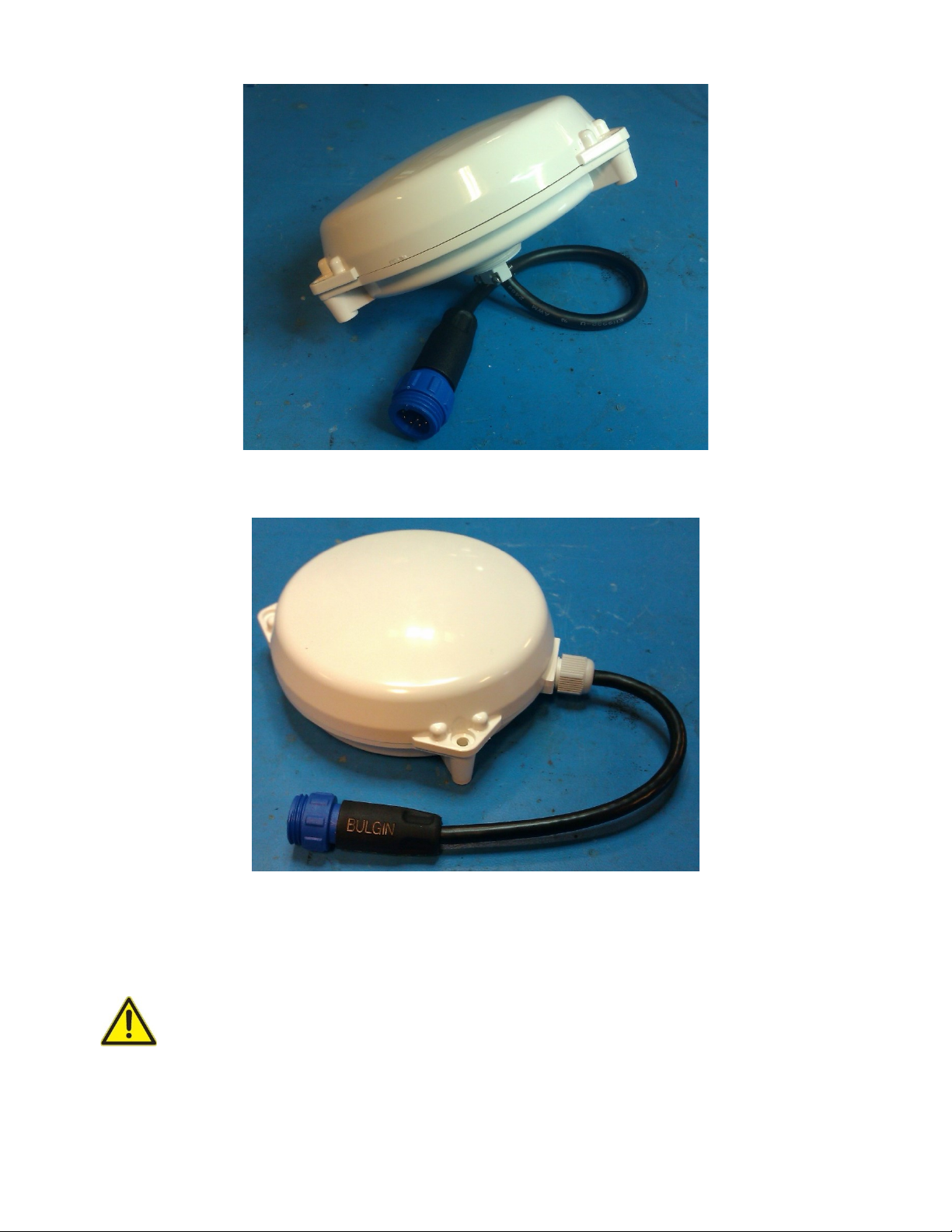
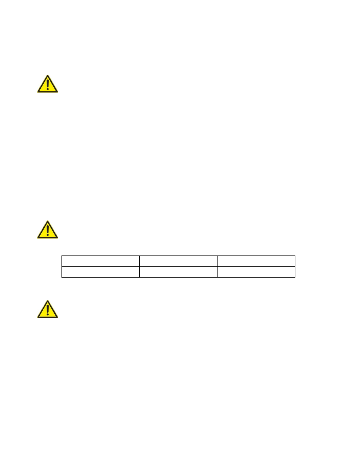
2.1 Model Types.................................................................6
Chapter 3 - Installation ..................................................8
3.1 Power Requirements...................................................... 8
3.2 Cable ...........................................................................8
3.3 Location....................................................................... 9
3.4 Mounting ...................................................................10
3.5 Applying Power ..........................................................13
3.6 Operational Check....................................................... 13
Chapter 4 - Functionality.............................................15
Chapter 5 –Factory Defaults ......................................16
Chapter 6 –Maintenance and Support ......................17
6.1 Cleaning.....................................................................17
6.2 Technical Support and Information................................ 17
Chapter 7 - Interfaces..................................................18
7.1 SAT-IDP Interface Pinout ............................................18
7.2 Interface Functions ......................................................18
7.3 General Purpose I/O ....................................................19
Chapter 8 –Interpreting the Indicator........................21
Chapter 9 –Security Guide.........................................22
9.1 Security Checklists.......................................................23
9.1.1 Infection by Malicious Software Agents ................23
9.1.2 Unauthorized External Access ..............................23
9.1.3 Unauthorized Internal Access ............................... 24
9.1.4 Accidental System Change................................... 25
9.2 Securing the Infrastructure ............................................26
9.2.1 Physical Location ............................................... 26
Appendix A –Specifications ......................................27
Appendix B –Warranty ...............................................29
Appendix C –Declaration of Conformity...................30
Appendix D –Inmarsat Type Approval ......................31
Appendix E –Product Information.............................32

MAN-0077 Honeywell Global Tracking Ltd 2
Preface
General Safety Warnings
WARNING: Before applying power to the equipment, the user must read all
instructions. If in any doubt, consult suitably trained service personnel.
WARNING: This product may contain magnetized material. Due care should be
taken when handling fully magnetized material as physical personal injury may
occur by the inadvertent attraction of magnetized material to other similar or ferro-
magnetic material.
WARNING: Close proximity (less than 100mm) to the magnetized material may
affect the operation of heart pacemakers.
WARNING: The SAT-401E magnetic feet are not designed for fitting to vehicles
driven at speed or over rough terrain. It is the user’s responsibility to ensure that
the equipment is secure when fitted to a vehicle and that the vehicle is driven
safely.
Note:
Retain this manual for future reference.
No user serviceable parts inside. Refer servicing to qualified service personnel.
The captive cable and gland nut on SAT-IDP is not user replaceable, tampering with these may void
the warranty. Damage to the cable could result in the terminal having to be replaced.
The equipment contains no replaceable fuses.
Observe all warnings on the equipment and in this manual.
Follow all installation and operating instructions.
Connect the equipment to a power supply only of the type described in the operating instructions or
marked on the equipment.
The unit should be located away from power lines.
Maximum Permissible Exposure (MPE) limits –This equipment complies with FCC (OET bulletin 65)
general population/uncontrolled exposure limits as applied to RF energy from a Mobile device. (A
mobile device being defined as a transmitting device designed to be used in other than fixed locations
and to be generally used in such a way that a separation distance of at least 20 centimetres is normally
maintained between the transmitter’s radiating structures and the body of the user or nearby persons.)

MAN-0077 Honeywell Global Tracking Ltd 3
Chapter 1 – Regulatory and Type Approval
1.1 Inmarsat Type Approval
The SAT-IDP has been certified for operation on the Inmarsat Network (Inmarsat Type Approval Certificate
Number xxxx–see Appendix D).
1.2 European Compliance
The equipment is designed, tested and declared to conform to the following European directives and standards
(The Declaration of Conformity can be found at Appendix C).
CE Mark
The SAT-IDP confirms all essential parts of the following directives:
RED Directive 2014/53/EU
Low Voltage Directive 2014/35/EU
EMC Directive 2014/30/EU
RoHS Directive 2011/65/EU
WEEE Directive 2002/96/EC
Relevant Standards
Radio standards per Article 3.2.: ETSI EN 301 426 v1.2.1
EMC standards per Article 3.1b): ETSI EN 301 489-20 v1.2.1
ETSI EN 301 489-1 v1.8.1
Safety standards per Article 3.1a): EN 62368-1
Ingress Protection Classification: EN60529:1999
1.3 FCC Authorisation
The following information is provided on the device covered in this document in compliance with FCC
regulations:
Model number: SAT-IDP (all variants)
Company Name: EMS Technologies Canada Ltd.
Honeywell Global Tracking CA
400 Maple Grove Rd
Ottawa ON K2V 188
CANADA
The product complies with FCC requirements:

MAN-0077 Honeywell Global Tracking Ltd 4
Sections 25.202 and 25.216 of FCC Title 47 of the Code of Federal Regulations (CFR).
FCC OET Bulletin 65 as applied to RF energy from a mobile device.
Pre-emption.
FCC statements:
1.This device complies with part 15 of the FCC rules. Operation is subjest to the following two condictions:
(1) This device may not cause harmful interference and (2) this device must accept any interference received,
including interference that may cause undesired operation.
2. FCC CFR:15.21 Information to user.
The users manual or instruction manual for an intentional or unintentional radiator shall caution the user that
changes or modifications not expressly approved by the party responsible for compliance could void the user's
authority to operate the equipment. In cases where the manual is provided only in a form other than paper, such as
on a computer disk or over the Internet, the information required by this section may be included in the manual in
that alternative form, provided the user can reasonably be expected to have the capability to access information in
that form.
3. FCC CFR 15.105:
For a Class B digital device or peripheral, the instructions furnished the user shall include the following or similar
statement, placed in a prominent location in the text of the manual:
NOTE: This equipment has been tested and found to comply with the limits for a Class B digital device, pursuant to part 15 of the FCC
Rules. These limits are designed to provide reasonable protection against harmful interference in a residential installation. This
equipment generates, uses and can radiate radio frequency energy and, if not installed and used in accordance with the instructions,
may cause harmful interference to radio communications. However, there is no guarantee that interference will not occur in a particular
installation. If this equipment does cause harmful interference to radio or television reception, which can be determined by turning the
equipment off and on, the user is encouraged to try to correct the interference by one or more of the following measures:
—Reorient or relocate the receiving antenna.
—Increase the separation between the equipment and receiver.
—Connect the equipment into an outlet on a circuit different from that to which the receiver is connected.
—Consult the dealer or an experienced radio/TV technician for help.
1.4 ISED compliance Statements
Operation is subject to the following two conditions:
1) This device may not cause interference.
2) This device must accept any interference, including interference that may cause undesired operation of the device.
Déclarations de conformité:
.L’exploitation est autorisée aux deux conditions suivantes :
(1) l’appareil ne doit pas produire de brouillage, et
(2) l’utilisateur de l’appareil doit accepter tout brouillage radioélectrique subi, même si le
brouillage est susceptible d’en compromettre le fonctionnement.

MAN-0077 Honeywell Global Tracking Ltd 5
Caution Statements:
• This equipment complies with radio frequency exposure limits set forth by Industry Cananda for an uncontrolled
environment.
• This equipment should be installed and operated with a minimum distance of 20 cm between the device and the user
or bystanders.
Déclarations de mise en garde:
• Cet équipement est conforme aux limites d'exposition aux radiofréquences defines par Indstrie Canada pourun
environment non contrôlé.
• Cet équipement doit être installé et utilisé aven un minimum de 20 cm de distancedispositif et l'utilisateur ou
des tiers.
1.5 Limitations on Intended Operating Environment
The SAT-IDP can be used in a wide range of control and monitoring applications. When third party equipment
is attached, such third-party equipment and all cabling must be of suitable design and installation to ensure
that the overall system complies with the requirements of the appropriate CE directives.
Guidance notes for the installation and use of the SAT-IDP must be strictly followed.
Honeywell Global Tracking exercises due diligence to ensure that the equipment is suitable for use in stated
applications, but ultimate responsibility for the compliance of a complete system must rest with the prime
contractor at a site where local conditions may require additional EMC precautions be taken.
WARNING: Changes or modifications to this unit not expressly approved by the
party responsible for compliance could void the user's authority to operate this
equipment and may void the warranty.

MAN-0077 Honeywell Global Tracking Ltd 6
Chapter 2 – General Description
This document refers to the SAT-IDP series, including their variants. Variants are indicated by alphabetic
suffixes. Most variants differ in physical characteristics only –for example bottom or side entry connector,
magnetic feet etc.
The SAT-IDP is a compact, single unit, low data rate satellite terminal, designed to operate over the Inmarsat
satellites using the IsatData Pro protocols. With an integral GPS receiver, the SAT-IDP provides low cost
satellite communications for applications such as asset tracking, telematics and SCADA exception reporting.
The SAT-IDP utilises five Inmarsat satellites providing near Global Coverage. Each satellite covers an ‘Ocean
Region’ (Global –Americas, Global - Europe, Middle East, Africa, Global - Asia Pacific, Spot - Atlantic Ocean
Region West South Central and Spot - Indian Ocean Region North East).
IsatData Pro mode of operation provides a data rate for the forward (to terminal) messages of approximately
3000 Symbols/second* with typical latency of: 100 bytes: 12 seconds; 1,000 bytes: 70 seconds**, Forward
channel can contain 2 to 6400 bytes**.
Return channel (from terminal) messages can contain 2 to 10,000 bytes** with a typical latency of: 100 bytes:
20 seconds; 1,000 bytes: 45seconds**. Traffic channel, on which messages to the terminal are received, is
determined from the internally stored configuration obtain from the Broadcast/Forward channel.
Mounting is via 3x M4 (No. 8) bolts or central M25 thread on base. Cable entry is from the centre base,
connector details are given on page 18.
* (As per IDP protocol spec- User bits are less than that because of protocol overheads)
** (For all latency, max size values are as per IDP protocol spec)
2.1 Model Types
The SAT-IDP Model Types consist of the standard model (as shown in Figure 1) and the variants shown in
Figure 2 and Figure 3. All units are functionally identical and only differ in that they offer various cable exit
and termination options, which may then be used with optional extension cables.
Figure 1 –SAT-IDP

MAN-0077 Honeywell Global Tracking Ltd 7
Figure 2 –SAT-IDP-BC
Figure 3 –SAT-IDP-SC
The SAT-401E incorporates three magnetic mounting feet for use as a portable solution.
WARNING: The SAT-IDP-SC magnetic feet are not designed for fitting to vehicles
driven at speed or over rough terrain. It is the user’s responsibility to ensure that
the equipment is secure when fitted to a vehicle and that the vehicle is driven
safely.

MAN-0077 Honeywell Global Tracking Ltd 8
Chapter 3 - Installation
IMPORTANT: Installation and service should only be carried out by suitably
qualified service personnel.
Local working practices and regulations for wiring and installations must be adhered to at all times.
3.1 Power Requirements
The equipment is powered from an external DC supply of 9.6V to 32V. The DC supply must be capable of
providing a maximum VA of 9.6W, for example 1A @ 9.6V or 0.3A @ 32V.
External power is connected via the 12-way connector (see page 18 for connector details and pin connections)
When installing the SAT-IDP, adequate circuit protection must be provided as required by local regulations.
IMPORTANT: If connecting to an external battery, the SAT-IDP requires an
external fast acting fuse connected in series with the +ve supply at the battery end
of the cable.
Input voltage
Fuse rating
Minimum wire gauge
9.6 to 32 VDC
2A
24 AWG (7/0.2)
IMPORTANT: If an external AC/DC Adaptor is used to power the equipment, it
must meet the requirements of EN 60950-1. The output of the Adaptor must also
meet the SELV limits of EN 60950-1.
3.2 Cable
It is recommended that cable routing is planned and operation tested before committing to a permanent
installation. The maximum cable diameter must not exceed 7mm, the maximum allowed by the terminal
connector.

MAN-0077 Honeywell Global Tracking Ltd 9
The SAT-IDP is supplied without cable or mating connector as standard. Suitable cables and/or
connectors can be purchased separately from your equipment supplier or authorised dealer. See page
18 for connector and pin out details.
When routing the cable avoid sharp edges and pinches.
Be aware of the minimum static bend radius of the cable.
Mechanical pressure on the cable may cause loss of functionality or even a short circuit and
subsequent damage to the terminal.
Use only shielded cables for connecting to peripherals. Using shielded cables ensures that the
appropriate EMC classifications are maintained.
The captive cable on the SAT-IDP-BC, SAT IDP-SC, SAT-401C and SAT-401E is not user replaceable,
tampering with the cable or their fixing points may void the warranty. Damage to the cable could result
in the terminal having to be replaced.
3.3 Location
The SAT-IDP is only weatherproof if the interface connector is correctly mated. Please consult your
dealer if you are in any doubt.
The SAT-IDP should be located with an unobstructed, clear view of the sky.
The SAT-IDP should be mounted on a flat horizontal surface.
Consider the position of the satellites. The Inmarsat satellites are in geostationary orbits above the
equator. (i.e., in the Northern hemisphere the satellites are located to the South; in the Southern
hemisphere the satellites are located to the North.) The further away from the Equator the SAT-IDP is,
the lower the degree of elevation will be above the horizon.
If you plan to install the SAT-IDP in a partially enclosed environment, test operation before committing
to a permanent installation.
On vehicles, the SAT-IDP should be located on the highest point possible, free from obstructions and
safe from damage during normal operation of the host vehicle.
For installations exposed to shock and/or vibration, use a mounting scheme that isolates the unit from
the excessive shock and/or vibration.
Choose a location that is not near radar installations, other satellite communication equipment, and/or
microwave dishes to prevent RF jamming.
Avoid mounting on hot surfaces.
Avoid prolonged exposure to anti-freeze, detergents, windscreen washer fluid and any other similar
chemicals.

MAN-0077 Honeywell Global Tracking Ltd 10
3.4 Mounting
If possible, try the installation before drilling any holes or fixing cable.
Record the unit ISN number (Inmarsat Serial Number) for future reference.
Fit the supplied rubber pads to the base of the SAT-401E to avoid damage to the vehicle.
The SAT-IDP and SAT-401C variants may be mounted by using either the three outer M4 mounting
holes or the M25 thread on the base.
The SAT-IDP-SC, SAT-401E is designed as a portable solution and does not require permanent fitting.
If using the three outer mounting holes (recommended for installations exposed to shock and/or high
vibration and/or uneven surfaces):
oBore a central 40mm hole.
oPosition the terminal centrally and mark the location of the three mounting holes.
oDrill three 4.5mm mounting holes.
oSecure the terminal in place using M4 (No.8) nuts and bolts - Do not over tighten (1.5Nm Max)
oAlternatively, secure using fastenings appropriate to the mounting surface - Do not over
tighten (1.5Nm Max).
If using the M25 base mounting thread:
oBore a 26mm hole to pass the connector (SAT-IDP only) and mounting thread through (and
cable on SAT-401C model).
oSecure using M25 nut - Do not over tighten (2.0Nm Max).
Do not paint the SAT-IDP enclosure.
Do not attach any foreign object to the enclosure anywhere above the three outer mounting holes.

MAN-0077 Honeywell Global Tracking Ltd 11
Figure 4 - SAT-IDP M4 Drilling Diagram (not to scale)
Figure 5 - SAT-IDP M25 Drilling Template (not to scale)

MAN-0077 Honeywell Global Tracking Ltd 12
Figure 6 - SAT-401C M25 Drilling Template (not to scale)
Figure 7 - SAT-IDP Foam Washer Dimensions (not to scale)

MAN-0077 Honeywell Global Tracking Ltd 13
3.5 Applying Power
Before connecting the SAT-IDP to an external voltage source, ensure that the polarity is correct and the
voltage source (at the input to the SAT-IDP) is between 9.6V and 32V. See page 18 for connector pin out
description. See page 8 for further details and requirements regarding the power source.
Check the circuit, in particular fuses and/or circuit protection devices.
Always ensure that the ground connection is connected before power is applied.
3.6 Operational Check
When the SAT-IDP first powers up, it starts its GPS receiver. After it has acquired its GPS position it identifies
the best Ocean Region to use and proceeds to acquire the IsatData Pro satellite signals. If, for some reason,
the unit is not able to obtain a valid GPS reading within two minutes, it will attempt to acquire IsatData Pro on
the default Ocean Region satellite (AORE).
If you wish to check the overall system operation it will be necessary to ensure that the terminal is activated on
a known gateway and that you have access to the application running there so that you can view the received
data. If you do not have access to an application of your own, it is possible to set up your terminal on one of
the Honeywell Global Tracking websites in order to perform end-to-end testing. Please consult your service
provider for details of the activation that has been put in place for your terminal. If you do not have access to
the application, it is still possible to check the local operation of the terminal and its installation by using the
following sequence. In this case it will then be necessary to check the application part of the system later.
With the SAT-IDP in position, apply power to the unit and monitor the indicator. The indicator cycles through
the patterns shown in the tables, with each state lasting for half a second.
RED
OFF
OFF
OFF
IsatData Pro Off
RED
OFF
GREEN
OFF
Acquiring Bulletin Board
GREEN
GREEN
RED
RED
Demodulating Bulletin Board*
GREEN
ORANGE
GREEN
OFF
Acquiring Traffic Channel
Once it has acquired the traffic channel, the unit will cycle through the following two states in normal operation.
GREEN
GREEN
GREEN
OFF
Demodulating Traffic Channel
GREEN
OFF
OFF
OFF
Idle part of TC Frame
The terminal will transmit its initial report (the indicator turns orange for 2 or 10 seconds) after successfully
demodulating the Traffic Channel. The total process to transmission will normally take less than one minute.
However, if the unit needs to acquire the Bulletin Board (see Chapter 8), this time could extend to as much as
eight minutes.

MAN-0077 Honeywell Global Tracking Ltd 14
Providing that your terminal has been activated and set up within an application, the data will be available
within approximately one minute of the actual transmission, although this is dependent on the operation of the
software being used by your service provider as well as the link to the Honeywell Global Tracking server.
Your service provider will be able to supply you with further details regarding the normal use of the terminal, as
well as scripts and forward channel use.
WARNING: The information in this chapter only applies to terminals that are set at
Factory Default and with the default script installed (see Chapter 5 –Factory
Defaults). If you are unsure about the state of your terminal, you should contact
your service provider.

MAN-0077 Honeywell Global Tracking Ltd 15
Chapter 4 - Functionality
For full functional details of the SAT-IDP contact your authorised dealer.

MAN-0077 Honeywell Global Tracking Ltd 16
Chapter 5 – Factory Defaults
The terminal is shipped with Factory Defaults set. When power is initially applied, the script timer, alarm and
operation definitions are cleared; the terminal then powers up, acquires the GPS position and tunes to the best
ocean region for the terminal location. Once the terminal has acquired the IDP satellite signal it transmits a
single position report burst.

MAN-0077 Honeywell Global Tracking Ltd 17
Chapter 6 – Maintenance and Support
6.1 Cleaning
Dust and finger marks can be removed using a soft damp cloth. Avoid using domestic cleaning products.
6.2 Technical Support and Information
For technical support, product queries and information please contact your equipment supplier or authorised dealer.
Alternatively, contact Honeywell Global Tracking directly for details of your dealer:
EMS Technologies Canada Ltd.
Honeywell Global Tracking CA
400 Maple Grove Rd
Ottawa ON K2V 188
CANADA
Support email: hgt-tracking-support@honeywell.com
General email: hgt-info@honeywell.com
General www: http://www.gt.honeywell.com

MAN-0077 Honeywell Global Tracking Ltd 18
Chapter 7 - Interfaces
The SAT-IDP interface connector is a 12 way plug that mates with a Bulgin Buccaneer 400 series socket.
Bulgin part numbers for the mating connector are:
1. Connector: PX0410/12S/6570
2. Solder contacts: SA3179/1 (pack of 10)
3. Crimp contacts: SA3179 (pack of 10). Contact Bulgin for crimp tool details
4. Insertion/extraction tool: 13027
Items 1, 2 and 4 can be purchased as a kit from your equipment supplier or authorised dealer (Honeywell
Global Tracking product number: A021B01).
7.1 SAT-IDP Interface Pinout
All SAT-IDP models have the following pin/cable connections:
Pin
Function
Cable colour code
(if supplied by Honeywell
Global Tracking)
1
0V (cable screen)
[Screen]
2
Voltage In (VIN+)
Red
3
0V (VIN-)
Orange
4
I/O 1
Yellow
5
OD_OUT
Green
6
I/O 3
Blue
7
I/O 2
Purple
8
Rx
Grey
9
Tx
White
10
0V (VIN-)
Black
11
I/O 4
Brown
12
I/O 5
Pink
7.2 Interface Functions
VIN+, VIN- External power input –9.6V to 32V DC
Tx, Rx RS232 serial control/data interface transmit (Tx) and receive (Rx) lines
4800 or 9600bps, asynchronous, no parity, 8 bit data, 1 stop bit. (For firmware upgrades,
rates up to 115200 bps can be selected.)
Control function –for configuring the unit
Data function –for message input/output
This manual suits for next models
3
Table of contents
Other Honeywell Marine GPS System manuals
Popular Marine GPS System manuals by other brands

Furuno
Furuno 1834C Operator's guide

MINN KOTA
MINN KOTA i-Pilot Quick reference guide

LXNAV
LXNAV E900 installation manual

Raymarine
Raymarine A65 Installation and operation instructions

Garmin
Garmin GPSMAP 292 - Marine GPS Receiver Declaration of conformity

Thrane&Thrane
Thrane&Thrane Explorer 727 Getting started