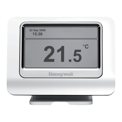
Honeywell T7771A Operation manual
Other Honeywell Temperature Controllers manuals
Honeywell
Honeywell H7625B User manual
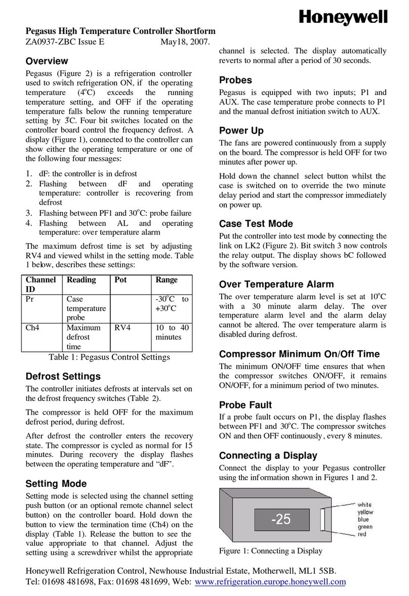
Honeywell
Honeywell Pegasus 190937-ZBC User manual
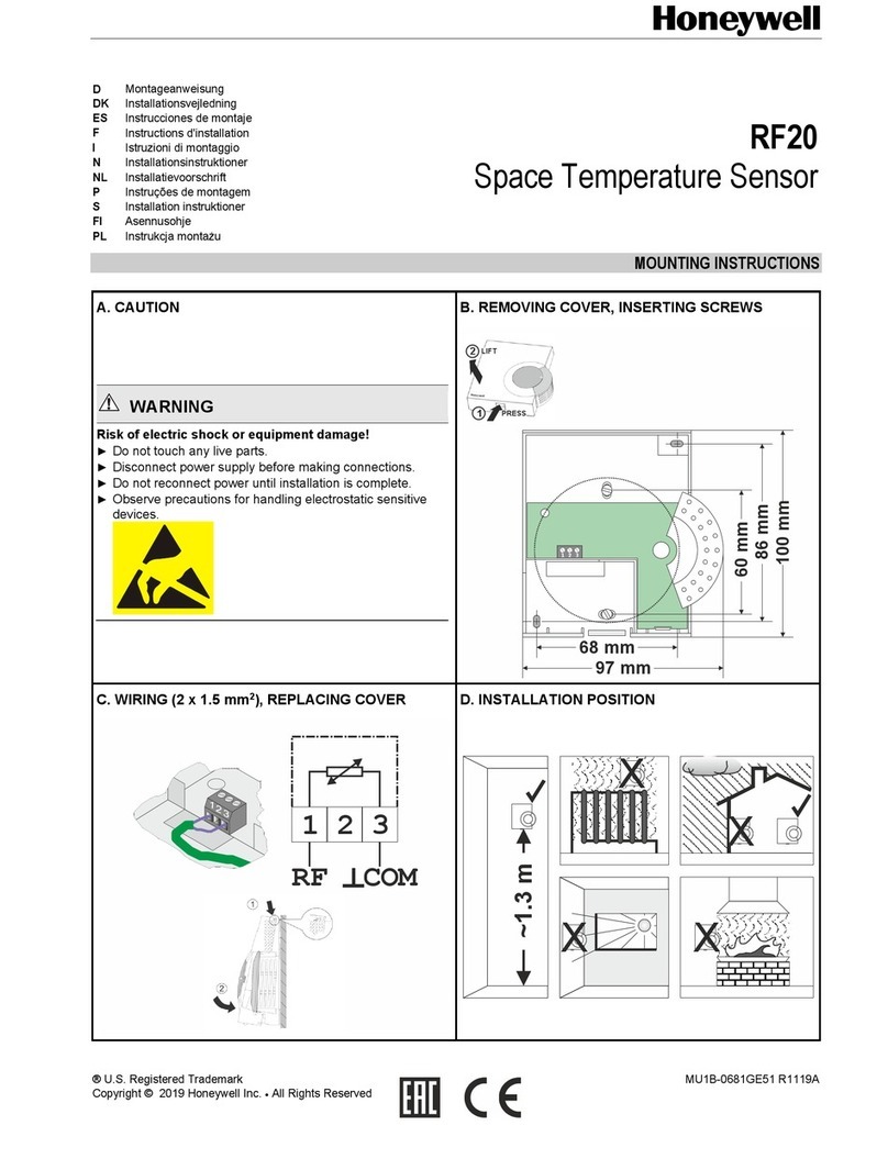
Honeywell
Honeywell RF20 User manual

Honeywell
Honeywell T775A Operation manual
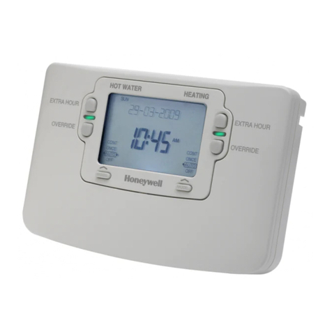
Honeywell
Honeywell ST9400S User manual

Honeywell
Honeywell C7189U User manual
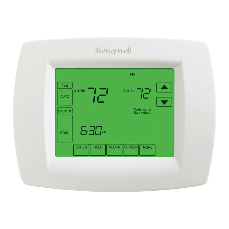
Honeywell
Honeywell VISIONPRO 68-0287-04 User manual

Honeywell
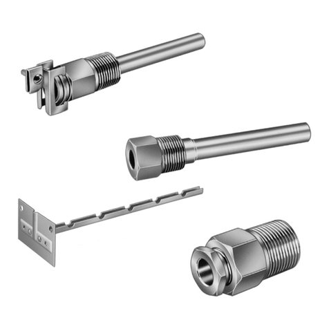
Honeywell L8104B User manual
Honeywell
Honeywell 121371B Operation manual
Honeywell
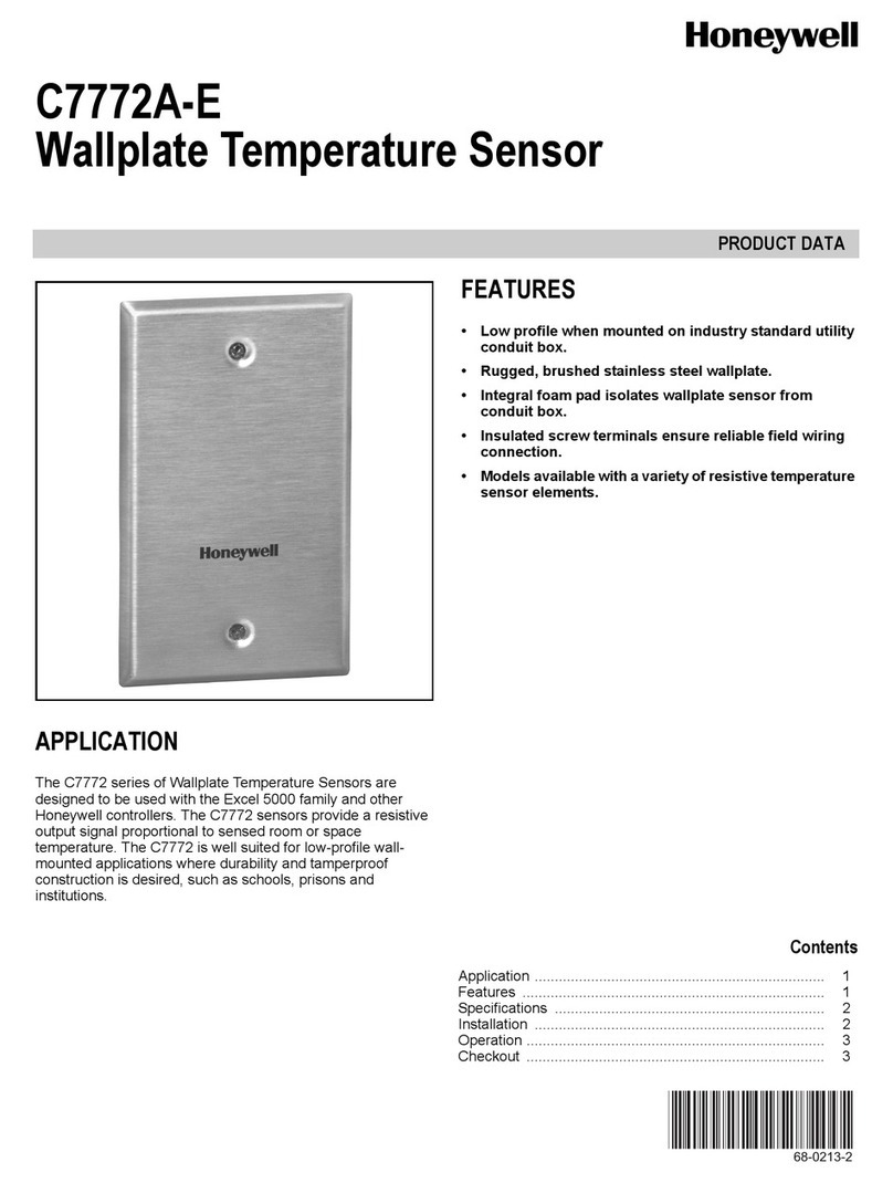
Honeywell C7772 Series Operation manual
Honeywell
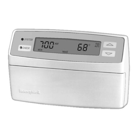
Honeywell PERFECT CLIMATE COMFORT CENTER User manual
Honeywell
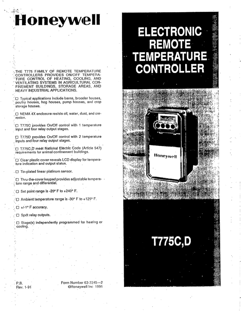
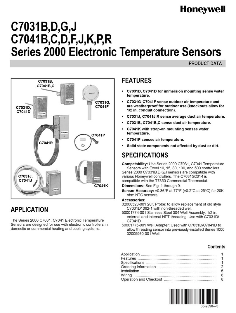
Honeywell T775C User manual
Honeywell
Honeywell PRO 2000 Series Operation manual
Honeywell
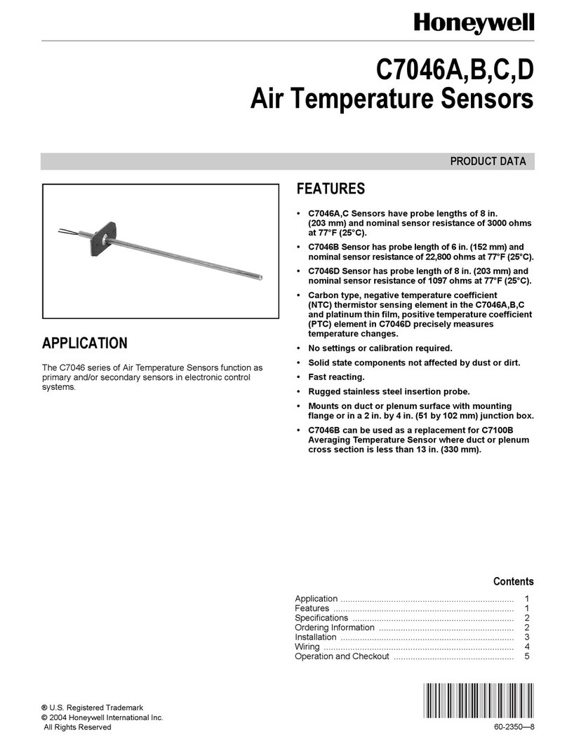
Honeywell C7046C Operation manual

Honeywell
Honeywell C7056A1001 User manual
Honeywell
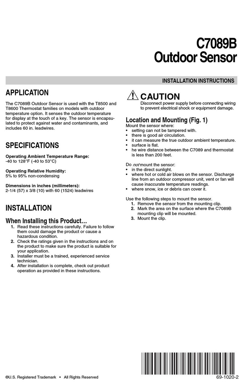
Honeywell C7089B User manual
Honeywell
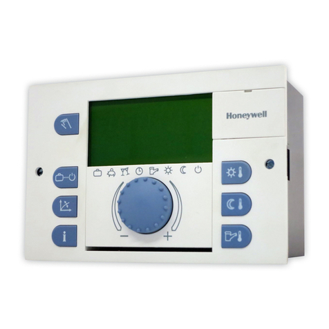
Honeywell Heating Controller SDC User manual
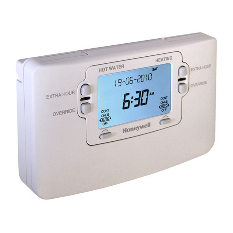
Honeywell
Honeywell ST9400C User manual
Honeywell
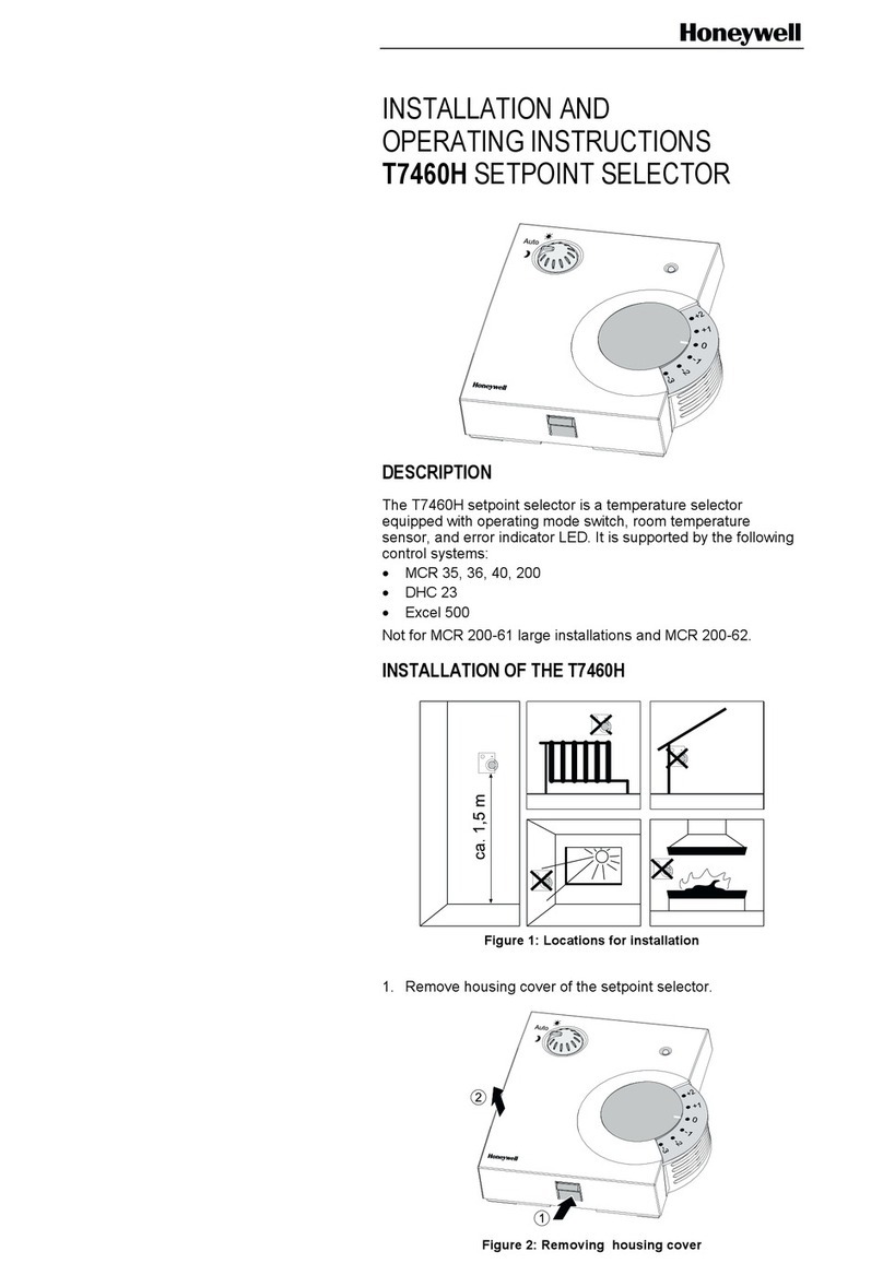
Honeywell T7460H User manual

Honeywell
Honeywell T775A User manual
Popular Temperature Controllers manuals by other brands

P.W. KEY
P.W. KEY rt-208gt operating manual

BH Thermal
BH Thermal BriskONE owner's manual

West Control Solutions
West Control Solutions KS 45 Operation Notes

MCS
MCS RITC-15B Operator's manual

SMC Networks
SMC Networks Thermo-con INR-244-639 Operation manual

eltherm
eltherm Ex-TC It Series operating instructions

Omron
Omron C200H-TV Series Operation manual

industrie technik
industrie technik CA1 instructions

KRAL
KRAL EET 32 operating instructions

dixell
dixell XR420C Installing and operating instructions

Opt Lasers
Opt Lasers TEC-8A-24V-PID-HC operating manual

Vaillant
Vaillant VR 92/3 Operating and installation instructions
