R7195A,B MOTOR POSITIONER
63-2582 8
a. Frequent re-positioning (hunting) of the motor.
b. Oscillation of the process variable around the
setpoint.
Check for unstable process conditions during initial startup of
the process. If unstable operation occurs, increase the
deadband adjustment (P2) until the cycling rate diminishes.
Hard Manual Check
Hard Manual allows the operator to override the controller
action to open or close fully the final control element (valve,
damper, etc.).
4-20 mA—Model 7195A
Connect terminal W to terminal B to drive the motor fully open.
Disconnect terminal W or terminal R to drive the motor fully
closed.
135-ohm Potentiometer—Model R7195B
Connect terminal W to terminal R to drive the motor fully
closed. Disconnect wire from Terminal W to drive the motor
fully open.
Troubleshooting
CAUTION
Equipment Damage Hazard.
Improper procedure can damage internal circuits.
To prevent triac damage, do not attempt to short
R7195 terminals 1, 2 or 3.
Motor Checkout Procedure
1. Identify wires on terminals 1 through 6 by terminal
number; then disconnect them from the terminals.
2. Connect an ohmmeter across wires 4 and 5 (feedback
slidewire).
3. Apply rated voltage across wires 1 and 2. Observe
gradual increase or decrease in feedback resistance.
4. Apply rated voltage across wires 2 and 3. Observe
gradual increase or decrease in feedback resistance.
If the motor functions properly, continue with the
troubleshooting procedure that follows.
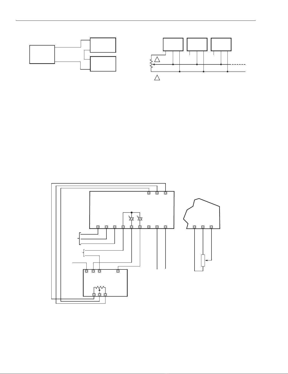
4-20 mA Input Applications
PRINTED WIRING BOARD
Refer to Fig. 10 and 11.
1. Connect the operating voltage leads to the appropriate
terminals and apply power (Fig. 10).
2. Set the motor at mid-range as follows:
a. Connect input source to terminals W and R, as
applicable to the motor.
b. Adjust the input source to mid-range.
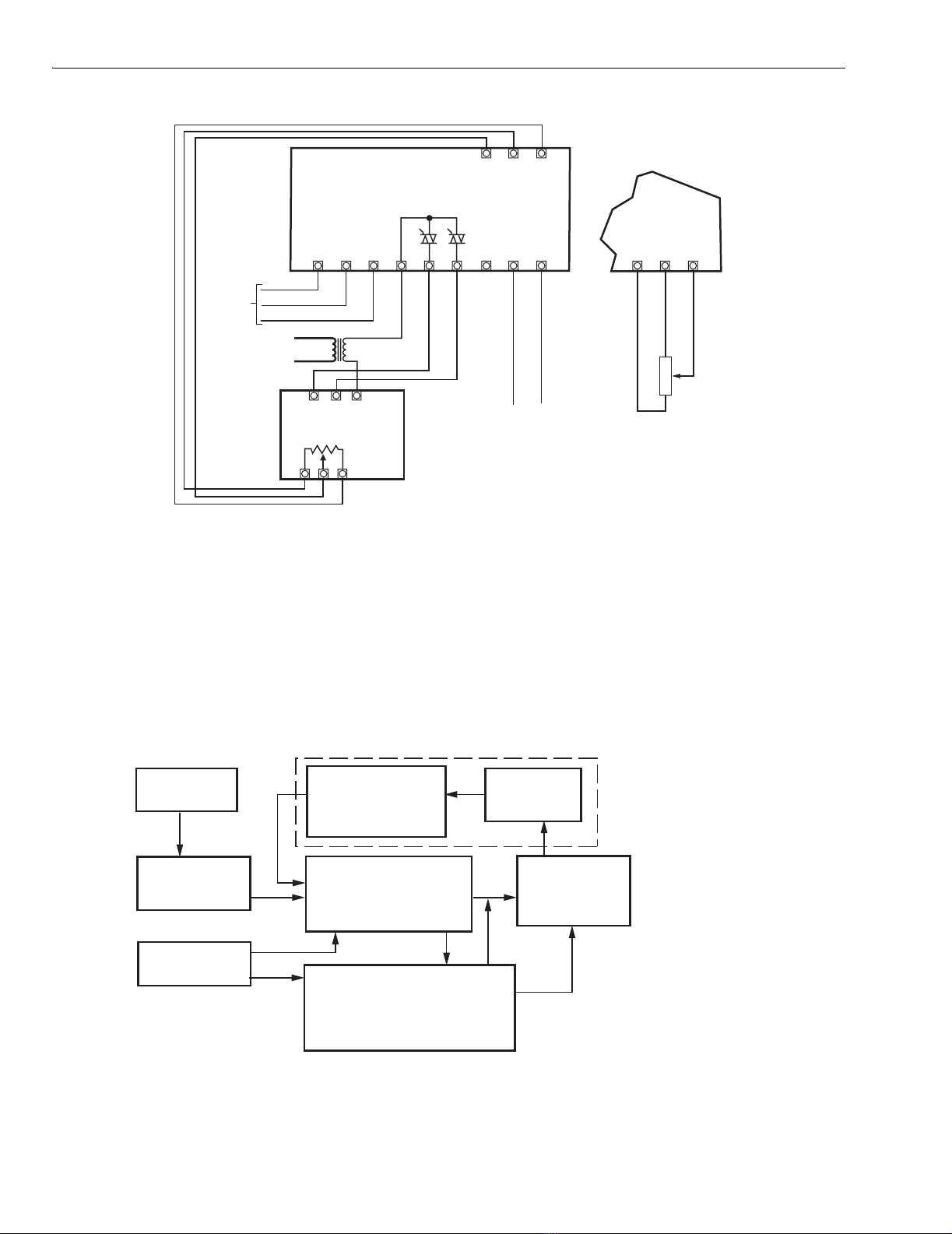
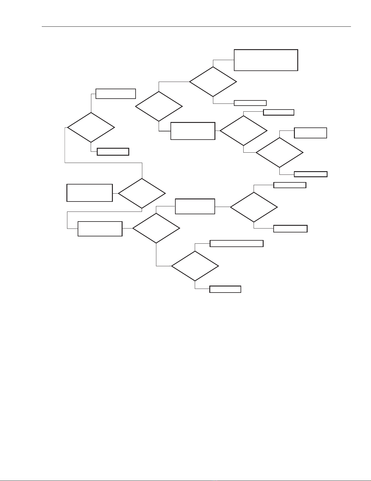
3. Refer to Fig. 11, a logic diagram to help you isolate
output circuit component failures on the printed wiring
board. Please refer to the appropriate literature for your
motor.
4. The types of component failures are listed below:
a. Shorted triac switches Q3 and Q4.
b. Q3 and Q4 break over at less than rated voltage.
c. Q3 and Q4 do not fire.
d. MOV (CR12) shorts.
5. If the logic diagram does not identify your
system-related problem, the failure is not in the output
circuit and the controller should be replaced or you may
use the schematic to troubleshoot the board.
NOTE: If your motor-motor controller system runs to fully
open or fully closed position, but fails to balance with
proper input conditions, it may be necessary to
reverse either motor power connections (1 and 3) or
feedback slidewire connections (4 and 6) at the
controller.
REVERSING DIRECTION OF THE MOTOR
Motor direction may be reversed as follows:
1. Interchange motor winding connections on terminals 1
and 3.
2. Interchange feedback potentiometer connections on ter-
minals 4 and 6.
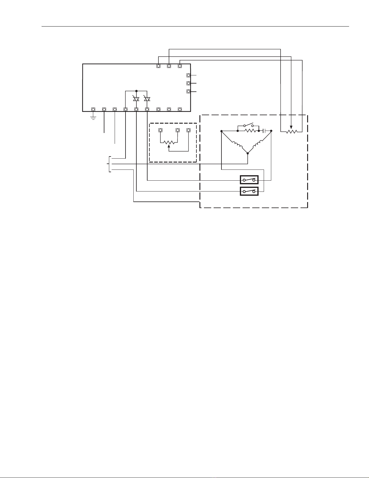
135-Ohm Input Applications
PRINTED WIRING BOARD
Refer to Fig. 10 and 11.
1. Connect the operating voltage to the appropriate
terminals and apply power.
2. Set the motor at mid-range as follows:
a. Connect input source to terminals B, W and R.
b. Adjust input source to mid-range.
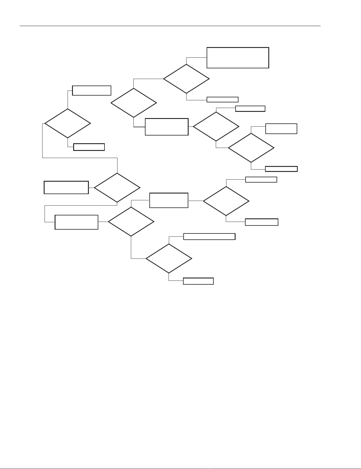
3. Refer to Fig. 11, a logic diagram to help you isolate
output circuit component failures on the printed wiring
board. Please refer to the appropriate literature for your
motor.
4. Types of component failures are listed below:
a. Shorted Triac switches Q3 and Q4.
b. Q3 and Q4 break over at less than rated voltage.
c. Q3 and Q4 do not fire.
d. MOV (CR12) shorts.
5. If the logic diagram does not identify your
system-related problem, the failure is not in the output
circuit and the controller should be replaced or you may
use the schematic to troubleshoot the board.
NOTE: If your motor-motor controller system runs to fully
open or fully closed position, but fails to balance with
proper input conditions, it may be necessary to
reverse either motor power connections (1 and 3) or
feedback slidewire connections (4 and 6) at the
controller.
REVERSING DIRECTION OF THE MOTOR
Motor direction may be reversed as follows:
1. Interchange motor winding connections on terminals 1
and 3.
2. Interchange feedback potentiometer connections on
terminals 4 and 6.