Honeywell NK300SE-SO-1/2A User manual

NK300SE-SO
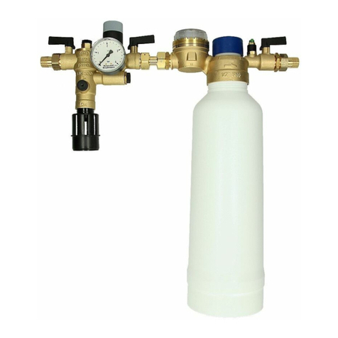
Einbauanleitung Installation instructions Notice de montage
Istruzioni di montaggio
Instrukcja montażu Návod na montáž
Anleitung zum späteren Gebrauch aufbewahren!
Keep instructions for later use!
Conserver la notice pour usage ultérieur!
Conservare le istruzioni per uso successivo!
Zachowa instrukcj do pózniejszego wykorzystania!
Návod uschovejte pro pozdější použití!
Nachfüllkombination mit Enthärtungspatrone
Refilling combination with softening cartridge
Combinaison de remplissage avec cartouche d'adoucissement
Gruppo di riempimento con cartuccia di addolcimento
Zespołu napełniającego z wkład zmiękczający
doplňovací kombinace se změkčovací patrony
S
e
r
v
i
c
e
ON
INFO
Wasserhärte
Hardness
Kartusche
Cartridge
Restkapazität
Ohne/ none
P300-LES
P300-LESxL
P300-S
P300-L
Verbrauch
Gesamtliter
Audio
3Sec.RESET
Kapazität
Capacity
Kartusche
Cartridge
Wechsel
Change
Gesamtliter
Totalliters
3Sec.RESET
NeueKartusche
NewCartridge
3Sec.Ventil/ValveModus
An/Aus
On/Off
EBA-NK300SE-SO 32317880-001

MU1H-1560GE23 R0516 Honeywell GmbH
D
1. Sicherheitshinweise ............................ 3
2. Lieferumfang ....................................... 3
3. Verwendung ....................................... 3
4. Technische Daten ............................... 3
5. Montage .............................................. 3
6. Inbetriebnahme ................................... 4
7. Instandhaltung .................................... 4
8. Entsorgung ......................................... 4
9. Störungen / Fehlersuche .................... 4
10. Serviceteile ......................................... 4
11. Zubehör .............................................. 4
GB
1. Safety Guidelines ............................... 5
12. Scope of delivery ................................ 5
13. Application .......................................... 5
14. Technical data .................................... 5
15. Assembly ............................................ 5
16. Start-up ............................................... 6
17. Maintenance ....................................... 6
18. Disposal .............................................. 6
19. Troubleshooting .................................. 6
20. Spare Parts ......................................... 6
21. Accessories ........................................ 6
F
1. Consignes de sécurité ........................ 7
22. Contenu de la livraiso ......................... 7
23. Mise en oeuvre ................................... 7
24. Caractéristiques techniques ............... 7
25. Montage .............................................. 7
26. Mise en service ................................... 8
27. Maintenance ....................................... 8
28. Matériel en fin de vie .......................... 8
29. Défaut / recherche de panne .............. 8
30. Apercu pièces ..................................... 8
31. Accessoires ........................................ 8
I
1. Avvertenze di sicurezza ...................... 9
32. Fornitura ............................................. 9
33. Uso ..................................................... 9
34. Dati tecnici .......................................... 9
35. Montaggio ........................................... 9
36. Messa in servizio .............................. 10
37. Manutenzione ................................... 10
38. Smaltimento ...................................... 10
39. Guasti / Ricerca guasti ..................... 10
40. Pezzi di ricambio .............................. 10
41. Accessori .......................................... 10
PL
1. Wskazówki bezpieczeDstwa ............ 11
2. Zakres dostawy ................................ 11
3. Zastosowanie ................................... 11
4. Dane techniczne ............................... 11
5. Montaż.............................................. 11
6. Uruchomienie ................................... 12
7. Utrzymywanie w dobrym stanie ........ 12
8. Usuwanie .......................................... 12
9. Zakłócenia / poszukiwanie usterek ... 12
10. Części zamienne .............................. 12
42. Wyposaøenie dodatkowe ................. 12
CZ
1. Bezpečnostní pokyny ....................... 13
2. Objem dodávky ................................. 13
3. Použití ............................................... 13
4. Technické údaje ............................... 13
5. Montáž .............................................. 13
6. Uvedení do provozu ......................... 14
7.
Údržba
................................................ 14
8. Likvidace ........................................... 14
9. Poruchy / hledání závady ................. 14
10. Náhradní díly .................................... 14
43. Příslušenství ..................................... 14

Honeywell GmbH 3 MU1H-1560GE23 R0516
D
1. Sicherheitshinweise
1. Beachten Sie die Einbauanleitung.
2. Benutzen Sie das Gerät
• bestimmungsgemäß
• in einwandfreiem Zustand
• sicherheits- und gefahrenbewusst.
3. Beachten Sie, dass das Gerät ausschließlich für den in
dieser Einbauanleitung genannten Verwendungsbereich
bestimmt ist. Eine andere oder darüber hinausgehende
Benutzung gilt als nicht bestimmungsgemäß.
4. Beachten Sie, dass alle Montage-, Inbetriebnahme,
Wartungs- und Justagearbeiten nur durch autorisierte
Fachkräfte ausgeführt werden dürfen.
5. Lassen Sie Störungen, welche die Sicherheit beeinträch-
tigen können, sofort beseitigen.
2. Lieferumfang
NK300SE-SO besteht aus einer Nachfüllkombination
(NK300S), die einen Systemtrenner, Druckminderer und
Absperrkugelhähne vereinigt, einer Nachfülleinheit (VE300S)
und einer Enthärterpatrone (P300-L).
3. Verwendung
4. Technische Daten
5. Montage
Beim Einbau sind die Einbauanleitung, geltende Vorschriften
sowie die allgemeinen Richtlinien zu beachten.
5.1. Einbauhinweise
• Installation im Zulauf der Heizungsanlage, Nachfülleinheit
(VE300S) an der Wand befestigen
• Einbau in waagrechte Rohrleitung mit Ablaufanschluss
bzw. Kartuschenanschluss nach unten
• Einbauhöhe min. 610 mm vom Boden aus vorsehen, um
Kartuschentausch sicher zu gewährleisten
• Nach der Nachfülleinheit (VE300S) mind. 500 mm Beruhi-
gungsstrecke bis zur Einbindung in den Heizkreislauf
vorsehen.
• Der Einbau darf nicht in Räumen oder Schächten erfolgen,
in denen giftige Gase oder Dämpfe auftreten und die über-
flutet werden können (Hochwasser)
• Der Einbauort muss frostsicher und gut belüftet sein
• Der Einbauort muss gut zugänglich sein
- Vereinfacht Wartung und Reinigung
- Manometer am Druckminderer kann gut beobachtet
werden
• Gemäß DIN EN 1717 in Durchflussrichtung zunächst
Nachfüllkombination (NK300S), dann unmittelbar danach
Nachfülleinheit (VE300S) installieren
• Bei der Montage sind die nationalen Installationsvor-
schriften zu beachten.
Medium Wasser
Vordruck max. 10.0 bar
Hinterdruck einstellbar von 1,5-4 bar
voreingestellt auf 1,5 bar
Flüssigkeitskategorie
Systemtrenner BA
4 (giftige, sehr giftige, krebserzeu-
gende, radioaktive Stoffe)
Geeignet für Heizungsanlagen mit folgenden Werk-
stoffen: Stahl, Kupfer, Kupferlegierungen und Kunst-
stoffe.
Aufbereitetes Wasser hat veränderte korrosionschemi-
sche Parameter. Eine Konditionierung mittels Inhibi-
toren ist separat vorzusehen.
Einbaulage waagrecht mit Ablaufanschluss
nach unten
Betriebstemperatur max. 30 °C
kvs-Wert 0,30 m3/h
Anschluss Kugelhahn
Systemtrenner
G 1/4"
Ablaufanschluss HT 40
Anschlussgröße 1/2" Außengewinde

MU1H-1560GE23 R0516 4 Honeywell GmbH
D
5.2. Montageanleitung
1. Rohrleitung gut durchspülen
2. Nachfüllkombination (NK300S) einbauen
• Einbau in waagrechte Rohrleitung mit Ablaufanschluss
nach unten
• Durchflussrichtung beachten (Pfeilrichtung)
• spannungs- und biegemomentfrei einbauen
3. Ablaufleitung an Ablaufanschluss anschließen (Kunst-
stoffrohr HT 40)
4. Nachfülleinheit (VE300S) unmittelbar nach der Nachfüll-
kombination (NK300S) einbauen und mittels der Wand-
halterung befestigen
• Einbau in waagrechte Rohrleitung
• Durchflussrichtung beachten (Pfeilrichtung)
• spannungs- und biegemomentfrei einbauen
5. Kartusche in die Nachfülleinheit schrauben und handfest
anziehen
6. Inbetriebnahme
1. Hinterdruck einstellen (siehe EBA-NK300S)
2. Enthärtung einstellen (Siehe EBA-VE300S)
3. Anlage füllen (siehe EBA-VE300S)
7. Instandhaltung
7.1. Inspektion
7.1.1. Durchzuführende Inspektionen
1. Funktionskontrolle Druckminderer (siehe EBA-NK300S)
2. Funktionskontrolle Ablassventil (siehe EBA-NK300S)
7.2. Wartung
Entsprechend DIN EN 1717 muss eineregelmäßige Wartung
durchgeführt werden.
7.2.1. Durchzuführende Wartungsarbeiten
1. Ventileinsatz und Sieb (siehe EBA-NK300S)
2. Kartuscheneinsatz warten und reinigen
(siehe EBA-NK300S)
3. Rückflussverhinderer (siehe EBA-NK300S)
4. Austausch Enthärterpatrone (siehe EBA-VE300S)
7.3. Reinigung
8. Entsorgung
9. Störungen / Fehlersuche
10. Serviceteile
11. Zubehör
Um stagnierendes Wasser zu vermeiden ist die Nach-
füllkombination (NK300S) möglichst nah an die Versor-
gungsleitung anzuschließen!
Bei der Montage gelten die nationalen Installationsvor-
schriften.
Kunststoff-Verschlussstopfen nur handfest anziehen
(ohne Werkzeug)
Informationen zu Inbetriebnahme siehe Anleitungen der
Einzelkomponenten (im Lieferumfang enthalten)
Instandhaltung von Systemtrennern darf nur durch
autorisiertes Fachpersonal erfolgen!
• Intervall: alle 6 Monate (abhängig von den örtlichen
Bedingungen)
• Durchführung durch ein Installationsunternehmen
Informationen zur Inspektion siehe Anleitungen der
Einzelkomponenten (im Lieferumfang enthalten)
Wir empfehlen einen Instandhaltungsvertrag mit einem
Installationsunternehmen abzuschließen
Intervall: 1-3 Jahre (abhängig von den örtlichen Bedin-
gungen)
Durchführung durch ein Installationsunternehmen.
Informationen zur Wartung siehe Anleitungen der
Einzelkomponenten (im Lieferumfang enthalten)
Ermittlung der maximalen Kapazität der Enthärterpa-
trone siehe EBA-P300L
Zur äußeren Reinigung der Kunststoffteile keine
lösungsmittel- und/oder alkoholhaltigen Reinigungs-
mittel benutzen, da dies zu Schädigung der Kunststoff-
bauteile führen kann - die Folge kann ein
Wasserschaden sein!
Es dürfen keine Reinigungsmittel in die Umwelt oder
Kanalisation gelangen!
Informationen zur Entsorgung siehe Anleitungen der
Einzelkomponenten (im Lieferumfang enthalten)
Die örtlichen Vorschriften zur ordnungsgemäßen Abfall-
verwertung bzw. Beseitigung beachten!
Informationen zu Störungen / Fehlersuche siehe Anlei-
tungen der Einzelkomponenten (im Lieferumfang
enthalten)
Informationen zu Serviceteilen siehe Anleitungen der
Einzelkomponenten (im Lieferumfang enthalten)
Informationen zu Zubehör siehe Anleitungen der Einzel-
komponenten (im Lieferumfang enthalten)

Honeywell GmbH 5 MU1H-1560GE23 R0516
GB
1. Safety Guidelines
1. Follow the installation instructions.
2. Use the appliance
• according to its intended use
• in good condition
• with due regard to safety and risk of danger.
3. Note that the appliance is exclusively for use in the appli-
cations detailed in these installation instructions. Any
other use will not be considered to comply with require-
ments and would invalidate the warranty.
4. Please take note that any assembly, commissioning,
servicing and adjustment work may only be carried out by
authorized persons.
5. Immediately rectify any malfunctions which may influence
safety.
2. Scope of delivery
NK300SE-SO consists of a refilling combination (NK300S)
that combines a backflow preventer, pressure reducing valve
and ball valves, a refilling unit (VE300S) and a softening cart-
ridge (P300-L).
3. Application
4. Technical data
5. Assembly
It is necessary during installation to follow the installation
instructions, to comply with local requirements and to follow
the codes of good practice.
5.1. Installations Guidelines
• Installation in the inlet to the heating system, fasten the
refill unit (VE300S) to the wall
• Install in horizontal pipework with discharge connection
respectivly cartridge connection directed downwards
• Install at height of at least 610 mm from the ground to
ensure that cartridges can be replaced
• Downstream of the refilling unit (VE300S), provide settling
section of at least 500 mm before integration in the heating
circuit.
• The installation may not take place in areas or ducts where
poisonous gases or vapours may be present or where floo-
ding can occur
• The installation environment should be protected against
frost and ventilated well
• The installation location has to be easily accessible
- Simplified maintenance and cleaning
- Pressure gauge at the pressure reducing valve can be
read off easily
• Acc. to EN 1717 in direction of flow, first install the refilling
combination (NK300S) and directly after it, the refill unit
(VE300S)
• The national installation regulations must be observed
during the assembly.
Medium Water
Inlet pressure max. 10.0 bar
Outlet pressure 1.5-4 bar adjustable, preset to 1.5
bar
Liquid category Backflow
preventer BA
4 (toxic, highly toxic, tumouri-
genic, radioactive materials)
Suitable for heating systems with the following mate-
rials: steel, copper, copper alloys and plastics.
Treated water has modified corrosive chemical para-
meters. Conditioning by means of inhibitors is to be
provided for separately.
Installation position horizontal pipework with
discharge connection directed
downwards
Operating temperature max. 30 °C
kvs-value 0.30 m3/h
Connection ball valve
Backflow preventer
G 1/4"
Connection size discharge HT 40
Connection size 1/2" External thread

MU1H-1560GE23 R0516 6 Honeywell GmbH
GB
5.2. Assembly instructions
1. Thoroughly flush pipework
2. Install the refilling combination (NK300S)
• Install in horizontal pipework with discharge connection
directed downwards
• Note flow direction (indicated by arrow)
• Install without tension or bending stresses
3. Attach drain pipe to discharge connection (plastic pipe
40 mm)
4. Install the refilling unit (VE300S) immediately after the
refilling combination (NK300S) and fasten with the wall
holder
• Install in horizontal pipeline
• Note flow direction (indicated by arrow)
• Install without tension or bending stresses
5. Screw the cartridge into the refilling unit and tighten by
hand
6. Start-up
1. Adjust the back pressure (see instruction NK300S)
2. Adjust the softening level (see EBA-VE300S)
3. Fill the system (see EBA-VE300S)
7. Maintenance
7.1. Inspection
7.1.1. Inspections to be performed
1. Pressure reducing valve function control (see instruction
NK300S)
2. Drain valve function control (see instruction NK300S)
7.2. Maintenance
In accordance with DIN EN 1717 a regular maintenance must
be taken.
7.2.1. Maintenance tasks to be performed
1. Valve insert and screen (see instruction NK300S)
2. Maintenance and cleaning of cartridge insert
(see instruction NK300S)
3. Check valve (see instruction NK300S)
4. Replacement of the softening cartridge (see EBA-
VE300S)
7.3. Cleaning
8. Disposal
9. Troubleshooting
10. Spare Parts
11. Accessories
To avoid stagnating water the refilling combination
(NK300S) must be attached as directly as possible to
the service pipe!
The national installation regulations apply during the
assembly.
Only fasten the plastic sealing plugs by hand (without
tools)
For information on start-up, see the instructions of the
individual components (included in scope of delivery)
Maintenance of backflow preventer must be carried out
by authorized personnel!
• Frequency: every 6 month (depending on local
operating conditions)
• To be carried out by an installation company
For information on inspections, see the instructions of
the individual components (included in scope of deli-
very)
We recommend taking out a servicing contract with an
installation firm
Frequency: every 1-3 years (depending on local opera-
ting conditions)
To be carried out by an installation company
For information on maintenance, please refer to the
instructions of the individual components (included in
scope of delivery)
To determine the maximum capacity of the softening
cartridge, see instruction P300L
To clean the outside of plastic parts, do not use any
cleaning agents containing alcohol and/or solvents, as
these can cause damage to the plastic components,
which can result in water damage!
Detergents must not be allowed to enter the environ-
ment or the sewerage system!
For information on disposal, please refer to the instruc-
tions of the individual components (included in scope of
delivery)
Observe the local requirements regarding correct waste
recycling/disposal!
For information on malfunctions / trouble shooting,
please refer to the instructions of the individual compo-
nents (included in scope of delivery)
For information on replacement parts, please refer to
the instructions of the individual components (included
in scope of delivery)
For information on accessories, please refer to the
instructions of the individual components (included in
scope of delivery)

Honeywell GmbH 7 MU1H-1560GE23 R0516
F
1. Consignes de sécurité
1. Suivre les indications de la notice de montage.
2. En ce qui concerne l'utilisation de l'appareil
• Utiliser cet appareil conformément aux données du
constructeur
• Maintenir l'appareil en parfait état
• Respectez les consignes de sécurité
3. Il faut noter que cet équipement ne peut être mis en
oeuvre que pour les conditions d'utilisation mentionnées
dans cette notice. Toute autre utilisation, ou le non
respect des conditions normales d'utilisation, serait consi-
dérée comme non conforme.
4. Observer que tous les travaux de montage, de mise en
service, d'entretien et de réglage ne pourront être effec-
tués que par des spécialistes agréés.
5. Prendre des mesures immédiates en cas d'anomalies
mettant en cause la sécurité.
2. Contenu de la livraison
NK300SE-SO est composé d'une combinaison de recharge
(NK300S), qui réunit un disconnecteur, un réducteur de pres-
sion et des robinets d'arrêt à boisseau sphérique, d'une unité
de recharge (VE300S) et d'une cartouche d'adoucissement
(P300-L).
3. Mise en oeuvre
4. Caractéristiques techniques
5. Montage
Pour le montage, respecter la notice d’installation, les consi-
gnes en vigueur et les directives générales.
5.1. Dispositions à prendre
• Montage sur la conduite d'amenée de l'installation de
chauffage, fixer l'unité de recharge (VE300S) au mur
• Montage dans la tuyauterie horizontale avec raccorde-
ment de la conduite d'écoulement ou de la cartouche vers
le bas
• Prévoir une hauteur de montage minimale à 610 mm du
sol afin de garantir un remplacement de la cartouche en
toute sécurité
• Prévoir une distance de stabilisation d'au moins 500 mm
en aval de la recharge (VE300S) jusqu'au raccordement
au circuit de chauffage.
• Le montage ne doit pas être effectué dans des locaux ou
des conduits dans lesquels des gaz ou des vapeurs
toxiques apparaissentet qui peuvent être ventilés (montée
de l'eau)
• Le lieu de montage doit être protégé contre le gel et bien
aéré
• Le lieu de montage doit être accessible facilement
- Pour simplifier l'entretien et le nettoyage
- Pour observer facilement le manomètre situé sur le
réducteur de pression
• Installer d'abord la combinaison de recharge (NK300S),
puis la recharge (VE300S) directement en aval dans le
sens du débit conformément à la norme DIN EN 1717
• Lors du montage, les consignes d'installation nationales
en vigueur doivent être respectées.
Fluide Eau
Pression amont 10,0 bars max.
Pression aval réglable de 1,5-4 bar préréglé sur 1,5
bar
Catégorie de fluide
disconnecteur BA
4 (substances toxiques, très toxiques,
cancérigènes, radioactives)
Destiné aux installations de chauffage contenant les
éléments suivants : acier, cuivre, alliages cuivreux et
matières plastique.
L'eau traitée possède des paramètres de corrosion
chimiques différents. Un conditionnement au moyen
d'inhibiteurs de corrosion doit être prévu séparément.
Montage horizontal avec raccord d'évacua-
tion vers le bas
Température de
fonctionnement
30 °C max.
Valeur du kvs 0,30 m3/h
Raccord robinet à bois-
seau sphériquediscon-
necteur
G 1/4"
Raccord d'évacuation HT 40
Dimensions de
raccordement
1/2'' filetage extérieur

MU1H-1560GE23 R0516 8 Honeywell GmbH
F
5.2. Instructions de montage
1. Bien rincer la conduite
2. Monter la combinaison de remplissage (NK300S)
• Montage dans une conduite horizontale avec raccord
de sortie vers le bas
• Contrôlez la direction de l'écoulement (direction de la
flèche)
• Vérifier l'absence de contraintes anormales en traction
et en flexion
3. Raccorder la conduite de sortie au raccordement (tuyau
en plastique 40mm)
4. Monter l'unité de recharge (VE300S) directement en aval
de la combinaison de recharge () puis la fixer au moyen
du support muralNK300S
• Montage sur une conduite horizontale
• Contrôlez la direction de l'écoulement (direction de la
flèche)
• Vérifier l'absence de contraintes anormales en traction
et en flexion
5. Visser la cartouche dans l'unité de recharge et la serrer à
la main
6. Mise en service
1. Régler la pression aval (voir les instructions d'installation
du NK300S)
2. Régler l'adoucissement (voir les instructions d'installation
VE300S)
3. Remplir l'installation (voir les instructions d'installation du
VE300S)
7. Maintenance
7.1. Inspection
7.1.1. Inspections à réaliser
1. Contrôler le fonctionnement du réducteur de pression
(voir les instructions d'installation du NK300S)
2. Contrôler le fonctionnement de la vanne de purge (voir
les instructions d'installation du NK300S)
7.2. Maintenance
On devra réaliser une maintenance régulière conformément
à la norme DIN EN 1717.
7.2.1. Travaux de maintenance à réaliser
1. Insert de soupape et tamis (voir les instructions d'installa-
tion du NK300S)
2. Entretenir et nettoyer la cartouche (voir les instructions
d'installation du NK300S)
3. Clapet anti-retour (voir les instructions d'installation du
NK300S)
4. Remplacer la cartouche d'adoucissement (voir les
instructions d'installation du VE300S)
7.3. Nettoyage
8. Matériel en fin de vie
9. Défaut / recherche de panne
10. Apercu pièces
11. Accessoires
Afin d'éviter que l'eau stagne, raccorder la combinaison
de remplissage (NK300S) le plus près possible de la
conduite d'amenée !
Les consignes d'installation nationales en vigueur
prévalent lors du montage.
Serrer les bouchons de fermeture en plastique à la main
uniquement (sans outil)
Pour de plus amples informations sur la mise en
service, se reporter aux instructions d'installation des
différents éléments (comprises dans la livraison)
La remise en état du disconnecteur doit être réalisée
uniquement par du personnel qualifié et autorisé !
• Intervalle : tous les 6 mois (en fonction des condi-
tions locales)
• Réalisation par une entreprise d'installation
Pour de plus amples informations sur les inspections à
réaliser, se reporter aux instructions d'installation des
différents éléments (comprises dans la livraison)
Nous vous recommandons de souscrire un contrat de
maintenance avec une entreprise d'installation
Périodicité:De 1 à 3 ans en fonction des conditions
d'utilisation
Opération effectuée par un professionnel
Pour de plus amples informations sur la maintenance à
réaliser, se reporter aux instructions d'installation des
différents éléments (comprises dans la livraison)
Pour déterminer la capacité maximale de la cartouche
d'adoucissement, se reporter aux instructions d'installa-
tion du P300L
Pour le nettoyage des pièces en plastique extérieures,
ne pas utiliser des produits de nettoyage à base de
solvants et / ou d'alcool, ceux-ci risquant d'endom-
mager les composants en plastique, ce qui peut provo-
quer des dégâts des eaux !
Ne pas rejeter de produit détergent dans l'environne-
ment ou dans les canalisations!
Pour de plus amples informations sur l'élimination du
matériel, se reporter aux instructions d'installation des
différents éléments (comprises dans la livraison)
Se conformer à la réglementation pour l'élimination des
équipements industriels en fin de vie vers les filières de
traitement autorisées!
Pour de plus amples informations sur les défauts / la
recherche de panne, se reporter aux instructions
d'installation des différents éléments (comprises dans la
livraison)
Pour de plus amples informations sur les pièces, se
reporter aux instructions d'installation des différents
éléments (comprises dans la livraison)
Pour de plus amples informations sur les accessoires,
se reporter aux instructions d'installation des différents
éléments (comprises dans la livraison)

Honeywell GmbH 9 MU1H-1560GE23 R0516
I
1. Avvertenze di sicurezza
1. Rispettare le istruzioni di montaggio.
2. Utilizzare l'apparecchio
- secondo la destinazione d'uso
- solo se integro
- in modo sicuro e consapevoli dei pericoli connessi
3. Si prega di considerare che l'apparecchio è realizzato
esclusivamente per il settore d'impiego riportato nelle
presenti istruzioni d'uso. Un uso differente o diverso da
quello previsto è da considerarsi improprio.
4. Osservare che tutti i lavori di montaggio, di messa in
funzione, di manutenzione e di regolazione devono
essere eseguiti soltanto da tecnici specializzati e autoriz-
zati.
5. I guasti che potrebbero compromettere la sicurezza
devono essere risolti immediatamente.
2. Fornitura
NK300SE-SO è costituito da un gruppo di riempimento
(NK300S), che unisce un separatore di sistema, un riduttore
di pressione e i rubinetti d'intercettazione, un'unità di tratta-
mento dell'acqua di riscaldamento (VE300S) e una cartuccia
di addolcimento (P300-L).
3. Uso
4. Dati tecnici
5. Montaggio
Al montaggio è necessario osservare il manuale di
montaggio, le norme vigenti nonché le direttive generali.
5.1. Istruzioni di installazione
• Installazione nella tubazione di mandata dell'impianto di
riscaldamento, fissare l'unità di trattamento dell'acqua di
riscaldamento (VE300S) alla parete
• Montaggio in tubazione orizzontale con attacco di scarico
e/o attacco cartuccia verso il basso
• Prevedere un'altezza d'installazione di min. 610 mm da
terra, per garantire una sostituzione sicura della cartuccia
• Dopo l'unità di riempimento (VE300S) prevedere un
percorso di stabilizzazione di min. 500 mm fino all'integra-
zione nel circuito di riscaldamento.
• È vietata l'installazione in locali o pozzetti in cui si possano
generare gas o vapori nocivi e soggetti a allagamento
(acqua di piena)
• Il luogo di installazione deve essere protetto dal gelo e
deve essere ben ventilato
• Il luogo di installazione deve essere di facile accesso
- Rende più semplice la manutenzione e la pulizia
- Il manometro del riduttore di pressione deve essere
facilmente controllabile
• Secondo DIN EN 1717 installare nella direzione del flusso
prima il gruppo di riempimento () e subito a valle l'unità di
trattamento dell'acqua di riscaldamento (VE300S)NK300S
• Durante il montaggio devono essere rispettate le norme di
installazione nazionali.
5.2. Istruzioni di montaggio
1. Sciacquare bene la tubazione.
2. Installare il gruppo di riempimento (NK300S)
• Montaggio nelle tubazioni orizzontali con attacco dello
scarico verso il basso
• Osservare la direzione di flusso (direzione della freccia)
• senza tensione e momento flettente
3. Collegare il tubo di scarico all'attacco dello scarico (tubo
di plastica 40mm)
4. Installare l'unità di trattamento dell'acqua di riscalda-
mento (VE300S) subito dopo il gruppo di riempimento ()
e fissarla con il supporto a pareteNK300S
• Installazione su tubazione orizzontale
• Osservare la direzione di flusso (direzione della freccia)
• senza tensione e momento flettente
5. Avvitare la cartuccia nell'unità di trattamento dell'acqua di
riscaldamento e serrarla a mano
Mezzo acqua
Pressione a monte max. 10,0 bar
Pressione a valle regolabile per 1,5-4 bar
preimpostata su1,5 bar
Categoria liquidi sepa-
ratore di sistema BA
4 (sostanze nocive, molto nocive,
cancerogene, radioattive)
Indicato per impianti di riscaldamento realizzati nei
seguenti materiali: Acciaio, rame, leghe di rame e
materiale plastico.
L’acqua trattata ha parametri chimici corrosivi modifi-
cati. Un condizionamento con inibitori deve essere
previsto separatamente.
Posizione di installazioneorizzontale con attacco dello
scarico in basso
Temperatura di eserciziomax. 30 °C
kvsValore 0,30 m3/h
Attacco rubinetto d'inter-
cettazioneseparatore di
sistema
G 1/4"
Attacco dello scarico HT 40
Dimensioni attacchi 1/2" filettatura esterna
Per evitare acqua stagnante collegare il gruppo di riem-
pimento (NK300S) il più vicino possibile alla tubazione
di alimentazione!
Durante il montaggio rispettare le norme di installazione
nazionali.
Stringere i tappi in plastica esclusivamente a mano
(senza attrezzi)

MU1H-1560GE23 R0516 10 Honeywell GmbH
I
6. Messa in servizio
1. Regolare la pressione a valle (vedere le istruzioni per
NK300S)
2. Impostare l'addolcimento (vedere EBA-VE300S)
3. Riempire l'impianto (vedere EBA-VE300S)
7. Manutenzione
7.1. Ispezione
7.1.1. Controlli da eseguire
1. Controllo funzionale del riduttore di pressione (vedere le
istruzioni per NK300S)
2. Controllo funzionale della valvola di scarico (vedere le
istruzioni per NK300S)
7.2. Manutenzione
In conformità alla norma DIN EN 1717 bisogna eseguire una
manutenzione periodica.
7.2.1. Lavori di manutenzione da eseguire
1. Inserto valvola e filtro (vedere le istruzioni per NK300S)
2. Manutenzione e pulizia dell'inserto della cartuccia
(vedere le istruzioni per NK300S)
3. Impeditore di riflusso (vedere le istruzioni per NK300S)
4. Sostituzione della cartuccia di addolcimento (vedere
EBA-VE300S)
7.3. Pulizia
8. Smaltimento
9. Guasti / Ricerca guasti
10. Pezzi di ricambio
11. Accessori
Per le informazioni sulla messa in servizio, vedere le
istruzioni per l'uso dei singoli componenti (comprese nel
volume di fornitura)
La manutenzione dei disconnettore idraulico deve
essere eseguita soltanto da personale specializzato
autorizzato!
• Frequenza: ogni 6 mesi (dipendente dalle condizioni
locali)
• attraverso un'azienda di installazione
Per le informazioni sui controlli, vedere le istruzioni per
l'uso dei singoli componenti (comprese nel volume di
fornitura)
Consigliamo di stipulare un contratto di manutenzione
con un'azienda di installazione
Frequenza: ogni 1-3 anni (in base alle condizioni
presenti) Esecuzione ad opera di un'azienda di installa-
zione
Per le informazioni sulla manutenzione, vedere le istru-
zioni per l'uso dei singoli componenti (comprese nel
volume di fornitura)
Per la determinazione della capacità massima della
cartuccia di addolcimento, vedere le istruzioni per
P300L
Per la pulizia esterna delle parti in plastica non utilizzare
detergenti che contengono solventi e/o alcool poiché
potrebbero danneggiare i componenti in plastica; le
conseguenze potrebbero essere danni causati
dall'acqua!
Nell'ambiente o nella canalizzazione è necessario che
non venga scaricato alcun detergente!
Per le informazioni sullo smaltimento, vedere le istru-
zioni per l'uso dei singoli componenti (comprese nel
volume di fornitura)
Rispettare le norme locali relative al riciclaggio o allo
smaltimento a regola d'arte di rifiuti!
Per le informazioni su guasti / ricerca ed eliminazione
degli errori, vedere le istruzioni per l'uso dei singoli
componenti (comprese nel volume di fornitura)
Per le informazioni sui pezzi di ricambio, vedere le istru-
zioni per l'uso dei singoli componenti (comprese nel
volume di fornitura)
Per le informazioni sugli accessori, vedere le istruzioni
per l'uso dei singoli componenti (comprese nel volume
di fornitura)

Honeywell GmbH 11 MU1H-1560GE23 R0516
PL
1. Wskazówki bezpieczeDstwa
1. Przestrzegaęinstrukcji montażu.
2. Proszęużytkowaęurządzenie
•
zgodnie z jego przeznaczeniem
•
w nienagannym stanie
•
ze świadomościąbezpieczeństwa i zagrożeń
3. Proszęuwzględnię, że urządzenie przeznaczony jest
wyłącznie dla zakresu zastosowania określonego w
niniejszej instrukcji montażu. Każde inne lub
wykraczające poza to użytkowanie uznawane jest jako
niezgodne z przeznaczeniem.
4. Proszęuwzględnię, że wszystkie prace montażowe
mogąbyęwykonywane tylko przez autoryzowany
personel fachowy.
5. Wszystkie usterki, które mogąnaruszyębezpiec
zeństwo należy natychmiast usunąę.
2. Zakres dostawy
NK300SE-SO składa sięz kombinacji napełniającej
(NK300S) zawierającej rozłącznik systemów, reduktor
ciśnienia i odcinające zawory kulkowe z kurkiem kulistym,
jednostki napełniającej (VE300S) i wkładu zmiękczającego
(P300-L).
3. Zastosowanie
4. Dane techniczne
5. Montaż
Podczas montażu przestrzegaęinstrukcji montażu,
obowiązujacych przepisów oraz ogólnych zasad
5.1. Montaż
•
Montażw dopływie instalacji grzewczej, jednostka
napełniająca (VE300S) montowana na ścianie
•
Montażw poziomym przewodzie rurowym z przyłączem
odpływu lub przyłączem wkładu demineralizacyjnego do
dołu
•
W celu zapewnienia łatwej wymiany wkładów deminera
lizacyjnych zaplanowaćwysokość montażu min.
610 mm od podłogi.
•
Za jednostkądopełniającą(VE300S) zaplanowaćprzed
włączeniem w obieg grzewczy odcinek uspokajający o
długości min. 500 mm.
•
Nie wolno montowaęw pomieszczeniach lub szybach, w
których występujątrujące gazy lub pary i które mogłyby
ulec zalaniu (powódź)
•
Miejsce montażu musi byęwolne od mrozu i dobrze
przewietrzane
•
Miejsce montażu musi byęłatwo dostępne
- UŠatwia konserwacjÍ i czyszczenie
- Manometr przy reduktorze ciśnienia musi byędobrze
widoczny
•
Zgodnie z normąDIN EN 1717 w kierunku przepływu
należy najpierw zamontowaćkombinacjęnapełniającą
(), a bezpośrednio potem jednostkęnapełniającą
(VE300S)NK300S
•
Przy montażu należy przestrzegaęlokalnych krajowych
przepisów montażowych.
Czynnik Woda
Ciśnienie wejściowe maks. 10,0 bar
Ciśnienie wyjściowe regulowane od 1,5-4 barustawione
wstępnie na 1,5 bar
Kategorie cieczyizo
lator przepływu
zwrotnego BA
4 (materiały trujące, silnie trujące,
rakotwórcze, radioaktywne)
Przeznaczony do instalacji grzewczych wykonanych
z następujących materiałów: stal, miedź, stopy miedzi
i tworzywa sztuczne.
Uzdatniona woda ma zmienione parametry koro
zyjne. Należy oddzielnie przewidzieęzabezpieczenie
za pomocąinhibitorów korozji.
Pozycja montażowa poziomo, z przyBczem
odpBywowym ku doBowi
Temperatura robocza maks. 30 °C
Wartośę k
vs
0,30 m
3
/h
Przyłączenie zaworu kulko
wego z kurkiem kulis
tymRozłącznik systemów
G
1
/
4
"
Przyłącze odpływowe HT 40
Rozmiar przyłącza
1
/
2
" gwint zewnętrzny

MU1H-1560GE23 R0516 12 Honeywell GmbH
PL
5.2. Instrukcja montażu
1. Dokładnie przepłukaęprzewód przyłączeniowy
2. Wmontowaęzespółnapełniający (NK300S)
•
Montażpoziomy z zaworem spustowym skiero
wanym w dół
•
Przepływ w kierunku wskazanym przez strzałkę
•
w stanie wolnym od naprężeńi momentów
zginających
3. Podłączyęprzewód odpływowy do przyłącza
odpływowego (rury z tworzywa sztucznego 40 mm)
4. Zamontowaćjednostkęnapełniającą(VE300S)
bezpośrednio po kombinacji napełniającej () i przymo
cowaćza pomocąuchwytu przyściennegoNK300S
•
Montowaęrurociąg w poziomie
•
Przepływ w kierunku wskazanym przez strzałkę
•
w stanie wolnym od naprężeńi momentów
zginających
5. Wkręcićwkład do jednostki napełniającej i dokręcić
ręcznie
6. Uruchomienie
1. Ustawięciśnienie wsteczne (patrz instrukcja NK300S)
2. Ustawićzmiękczanie (patrz EBA-VE300S)
3. Napełnićurządzenie (patrz EBA-VE300S)
7. Utrzymywanie w dobrym stanie
7.1. Kontrola
7.1.1. Inspekcje które należy przeprowadzaę
1. Skontrolowaęfunkcjonowanie reduktora ciśnienia
(patrz instrukcja NK300S)
2. Skontrolowaęfunkcjonowanie zaworu spustowego
(patrz instrukcja NK300S)
7.2. Konserwacja
Zgodnie z DIN EN 1717 konieczna jest regularna konser
wacja.
7.2.1. Prace konserwacyjne które należy przepro
wadzaę
1. Wkładka zaworu i sito (patrz instrukcja NK300S)
2. Konserwacja i czyszczenia zespołu wkładki zaworu
(patrz instrukcja NK300S)
3. Zawór zwrotny (patrz instrukcja NK300S)
4. Wymiana wkładu zmiękczającego (patrz EBA-VE300S)
7.3. Czyszczenie
8. Usuwanie
9. Zakłócenia / poszukiwanie usterek
10. Części zamienne
11. Wyposażenie dodatkowe
Aby uniknąę stagnującej wody, należy zespół
napełniający (NK300S) podłączyęmożliwie blisko
instalacji zasilającej!
Przy montażu należy przestrzegaęlokalnych
krajowych przepisów montażowych.
Dokręcięmocno zaślepki, tylko ręcznie (bez użycia
narzędzi)
Informacje dotyczące rozruchu znaleźę można w
instrukcjach poszczególnych komponentów (należą
do zakresu dostawy)
Utrzymywanie izolatorów w stanie sprawności może
byęprzeprowadzane wyłącznie przez autoryzowany
personel specjalistyczny!
•
Okres: co 6 miesięcy (w zależności od panujących
na miejscu warunków)
•
Kontrole powinna przeprowadzięfirma instala
cyjna
Informacje dotyczące inspekcji znaleźę można w
instrukcjach poszczególnych komponentów (należą
do zakresu dostawy)
Zalecamy zawarcie umowy konserwacyjnej z firmą
instalacyjną.
Okres: raz w roku Przeprowadzenie przez firmę
instalacyjną
Informacje dotyczące prac konserwacyjnych znaleźę
można w instrukcjach poszczególnych komponentów
(należą do zakresu dostawy)
Ustalenie maksymalnej pojemności wkładu zmięk
czającego, patrz instrukcja P300L
Do czyszczenia powierzchni elementów z tworzywa
sztucznego nie wolno używaćśrodków czyszczących
zawierających rozpuszczalniki lub alkohol, ponieważ
mogłoby to spowodowaćuszkodzenie tych
elementów, a w konsekwencji — zalanie wodą.
Żadne środki czyszczące nie powinny dostaęsiędo
środowiska naturalnego lub kanalizacji!
Informacje dotyczące utylizacji znaleźę można w
instrukcjach poszczególnych komponentów (należą
do zakresu dostawy)
Należy stosowaęsiędo miejscowych przepisów
dotyczących prawidłowego wykorzystania odpadów
wzgl. ich usuwania!
Informacje dotyczące zakłóceń/ szukania błędów
znaleźę można w instrukcjach poszczególnych
komponentów (należą do zakresu dostawy)
Informacje dotyczące części zamiennych znaleźę
można w instrukcjach poszczególnych komponentów
(należą do zakresu dostawy)
Informacje dotyczące wyposażenia znaleźę można w
instrukcjach poszczególnych komponentów (należą
do zakresu dostawy)

Honeywell GmbH 13 MU1H-1560GE23 R0516
CZ
1. Bezpečnostní pokyny
1. Respektujte návod k montáži.
2. Používejte přístroj
•
přiměřenějeho účelu
•
v bezvadném stavu
•
bezpečněa s vědomím možných nebezpečí.
3. Dbejte na to, že přístroj je určen výhradněpro oblast
použití uvedenou v tomto návodu k montáži. Jiné, nebo
nad tento rámec jdoucí použití platí jako nepřiměřené.
4. Dbejte na to, že všechny montážní, údržbářské a nasta
vovací činnosti i uvádění do provozu smí provádět
pouze autorizovaný odborný personál.
5. Poruchy, které mohou ovlivnit bezpečnost, nechejte
neprodleněodstranit!
2. Objem dodávky
NK300SE-SO se skládá z doplkové kombinace (NK300S),
která spojuje systémový odpojova, redukní ventil a
uzavírací kulové kohouty, napouštcí jednotku (VE300S) a
patronu zmkovae (P300-L).
3. Použití
4. Technické údaje
5. Montáž
Při montáži je nutné dodržovat návod k montáži, platné
předpisy i všeobecné pokyny.
5.1. Pokyny pro instalaci
•
Instalace v pívodu topného zaízení, upevnte napouštcí
jednotku (VE300S) na stnu
•
Vestavba do vodorovného potrubí s pípojkou odtoku,
pop. kartuše smující dol
•
Výška vestavby min. 610 mm od zeměk zajištění
bezpečné výměny kartuše
•
Po napouštěcí jednotce (VE300S) připravit vyrovnávací
trasu dlouhou min. 500 mm až k napojení na topný
okruh.
•
Montáž nesmí probíhat v prostorech nebo šachtách, v
nichž se vyskytují plyny nebo páry, nebo které mohou
být zatopeny (velká voda).
•
Místo montáže musí být mrazuvzdorné a dobře větrané.
•
Místo montáže musí být dobře přístupné.
- Zjednodušená údržba a čištění
- Manometr na redukním ventilu je dobe viditelný
•
Podle SN EN 1717 instalujte ve smru prtoku nejprve
doplovací kombinaci (NK300S), pak bezprostedn za ní
napouštcí jednotku (VE300S)
•
U montáže je nutné dbát příslušných národních
předpisů.
Médium Voda
Vstupní tlak max. 10.0 bar
Výstupní tlak nastavitelný od 1,5 do 4 bar,
přednastavený na 1,5 bar
Kategorie
kapalin,systémový
odpojovačBA
4 (jedovaté, velmi jedovaté, rakovino
tvorné, radioaktivní látky)
Vhodné pro topná zařízení s těmito materiály: ocel,
měď, slitiny mědi a plasty.
Zpracovaná voda má změněné korozněchemické
parametry. Příprava prostřednictvím inhibitorůmusí
být provedena zvlášť.
Poloha při montáži vodorovněs připojením odtoku
dolů
Provozní teplota max. 30 °C
k
vs
-hodnota 0,30 m
3
/h
Pípojka kulový kohout
systémový odpojova
G
1
/
4
"
Připojení odtoku HT 40
Přípojná velikost
1
/
2
" Vnjší závit

MU1H-1560GE23 R0516 14 Honeywell GmbH
CZ
5.2. Návod k montáži
1. Dobře propláchnout potrubí
2. Montáž doplňovací kombinace (NK300S)
•
Montáž ve vodorovném potrubí s připojením odtoku
dolů.
•
Dejte pozor na správný směr průtoku (viz šipka)
•
Namontovat bez mechanického namáhání pnutím a
ohybem
3. Připojte odtokové potrubí kpřípojce odtoku (plastová
trubka 40mm)
4. Napouštcí jednotku (VE300S) vmontujte bezprostedn
po doplkové kombinaci (NK300S) a upevnte prosted
nictvím nástnného držáku
•
Montáž do vodorovného úseku potrubí
•
Dejte pozor na správný směr průtoku (viz šipka)
•
Namontovat bez mechanického namáhání pnutím a
ohybem
5. Do napouštcí jednotky našroubujte kartuši a run ji
utáhnte
6. Uvedení do provozu
1. Nastavte zadní tlak (viz montážní návod NK300S)
2. Nastavte zmkování (viz montážní návod VE300S)
3. Naplte zaízení (viz EBA-VE300S)
7. Údržba
7.1. Kontrola
7.1.1. Nutné kontrolní prohlídky
1. Kontrola funkce redukčního ventilu (viz montážní návod
NK300S)
2. Kontrola funkce vypouštěcího ventilu (viz montážní
návod NK300S)
7.2. Údržba
Podle DIN EN 1717 musí být údržba prováděna pravidelně.
7.2.1. Nutná údržba
1. Ventilová vložka a sítko (viz montážní návod NK300S)
2. Údržba a čištění kartuše (viz montážní návod NK300S)
3. Zábrana zpětného toku (viz montážní návod NK300S)
4. Výmna zmkovací patrony (viz montážní návod
VE300S)
7.3. Čištění
8. Likvidace
9. Poruchy / hledání závady
10. Náhradní díly
11. Příslušenství
K zabránění tvorběstagnující vody musí být doplňo
vací kombinace (NK300S) připojena v co největší
blízkosti napájecího potrubí!
Při montáži platí příslušné národní předpisy.
Plastovou uzavírací zátku dotahujte pouze rukou (bez
nářadí)
Informace o uvedení do provozu viz návody
jednotlivých součástí (jsou přiloženy k dodávce)
Údržbu systémového odpojovače smí provádět pouze
autorizovaný odborný personál!
•
Interval: Každých šest měsíců(v závislosti na míst
ních podmínkách).
•
Provedení prostřednictvím kontrolní firmy.
Informace o kontrolních prohlídkách viz návody
jednotlivých součástí (jsou přiloženy k dodávce)
Doporučujeme uzavřít smlouvu o údržběs podnikem
provádějícím instalaci.
Interval: 1-3 roky (v závislosti na místních
podmínkách). Provést prostřednictvím instalatérské
firmy.
Informace o údržbářských pracích viz návody
jednotlivých součástí (jsou přiloženy k dodávce)
Určení maximální kapacity změkčovací patrony viz
montážní návod P300L
K vnjšímu ištní plastových díl nepoužívejte isticí pros
tedky obsahující rozpouštdla anebo alkohol, protože
by to mohlo vést k poškození plastových díl,
následkem mže být škoda zpsobená vodou!
Do kanalizace nebo okolí se nesmí dostat žádné
čisticí prostředky!
Informace o likvidaci viz návody jednotlivých součástí
(jsou přiloženy k dodávce)
Respektujte místní předpisy pro správnou recyklaci
popř. likvidaci odpadu!
Informace o poruchách a vyhledávání závad viz
návody jednotlivých součástí (jsou přiloženy
k dodávce)
Informace o náhradních dílech viz návody
jednotlivých součástí (jsou přiloženy k dodávce)
Informace o příslušenství viz návody jednotlivých
součástí (jsou přiloženy k dodávce)

Honeywell GmbH 15 MU1H-1560GE23 R0516
CZ

Automation and Control Solutions
Honeywell GmbH
Hardhofweg
74821 MOSBACH
GERMANY
Phone: (49) 6261 810
Fax: (49) 6261 81309
http://ecc.emea.honeywell.com
Manufactured for and on behalf of the
Environmental and Combustion Controls Division of
Honeywell Technologies Sàrl, Z.A. La Pièce 16,
1180 Rolle, Switzerland by its Authorised Represen-
tative Honeywell GmbH
MU1H-1560GE23 R0516
Subject to change
© 2016 Honeywell GmbH
This manual suits for next models
1
Table of contents
Languages:
Other Honeywell Water System manuals
Popular Water System manuals by other brands

HydroCare
HydroCare Dual Action Installation, use & care guide

Hilti
Hilti DD-WMS 100 Safety sheet

Grunbeck
Grunbeck GENO-Neutra KW Operation manual

deconta
deconta C110 L 110V instruction manual

BRENNTAG
BRENNTAG HEATSAVR instruction manual

Stern Engineering
Stern Engineering SWAN 1000 AB1953 Installation and maintenance guide