Revision - 4 of 20
SECTION 1 –Tools Required
Socket wrench set
Combination wrench set
Wire cutters
Screw drivers
In addition to the above items, you may need shop supplies such as electrical tape, wire
ties, thread locking compound, or RTV silicone.
SECTION 2 –About your Audio Shade Top
2.1 Applicable Year Models:
This Audio Shade off-road top is designed to fit the following Kawasaki Teryx KRX
1000 models:
2020-2023 Teryx KRX 1000 (all 2 seat versions)
All versions means it includes sub models such as Base, eS, Special Edition, and
Trail Edition.
This system is compatible with most front full windshields that work with the
factory plastic roof.
Accessories that mount overhead on the roll cage such as wiper motors, etc. may
not be compatible or may require modification. Contact Hoppe customer service
for questions.
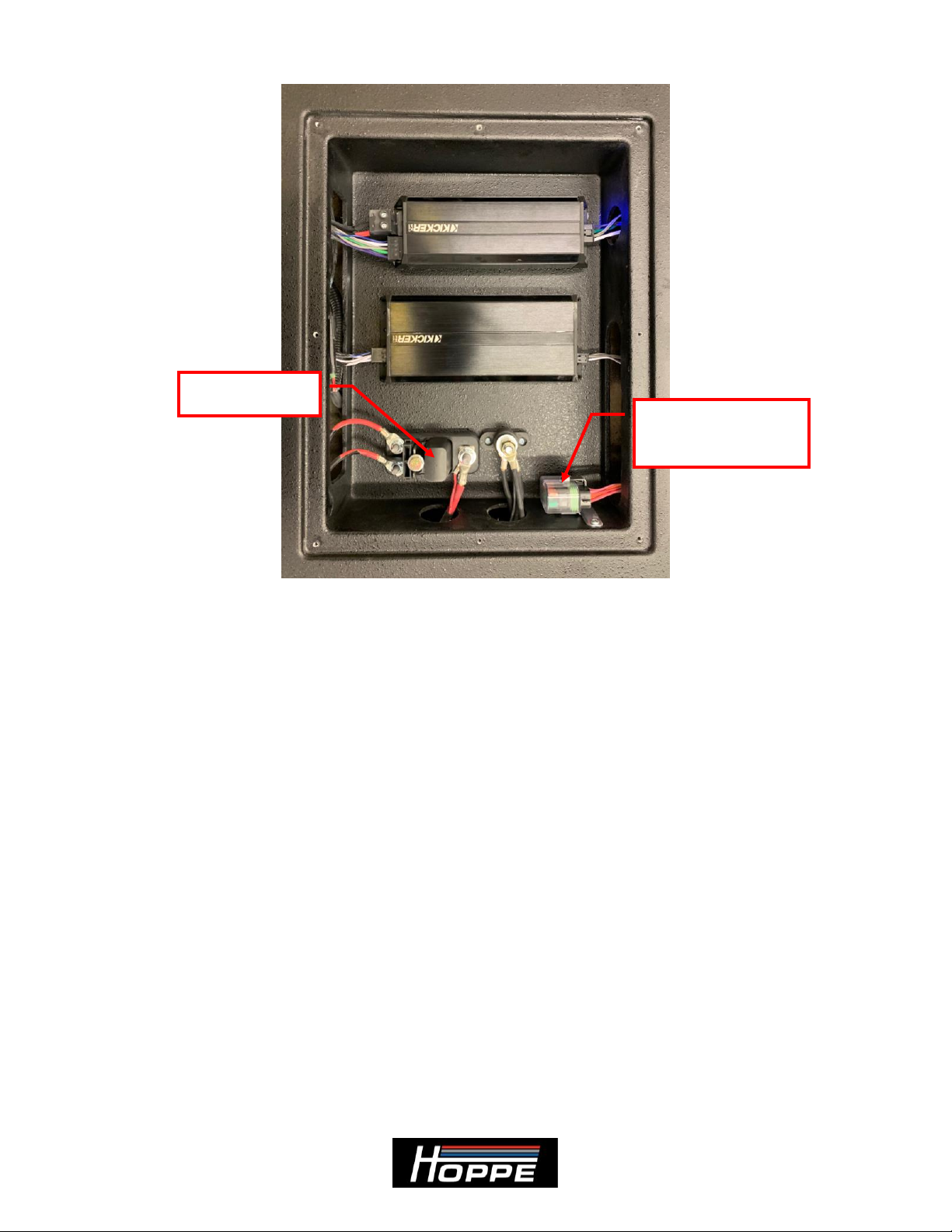
2.2 Audio Equipment Details:
Your Audio Shade off-road top is powered by using their
premium quality power sports series audio equipment. This equipment is designed to
function in all weather conditions. The stereo is specifically engineered to provide
excellent sound quality and volume in an open air power sports enviroment so you can
enjoy your music on the go.
To learn more details about your stereo system, you can access product information and
manuals for the stereo equipment here: www.kicker.com
Your amplifier gains come pre-adjusted from the factory and are tuned for optimum
sound quality and system protection. This means you can feel free to crank the volume
without much worry of harming your system. However, it is wise to use a little common
sense. If you hear any distortion, back off a little. We recommend you do not adjust the
gains from the factory settings without first consulting Hoppe Industries.
Please note that your subwoofer will take 20 to 30 hours of play time to fully break in and
reach its maximum output. You do not need to do anything different during this break in