Product Handling Information
Operational precautions
Use of the product in a manner not specified by the manufacturer may impair the protection
provided by the product. And it may also reduce product performance.
Exercise the following precautions:
Some parts such as laser diode or scanning unit must be replaced every four years.
Severe condition (high temperature, continuous vibration) may make the life span short.
Consult us when you need repairs or technical support about the LO-300.
Wave by the strong window or splash by heavy rain may influence oil detection though the
instrument is designed to reject these obstructions. Good oil detection results by flat water
surface.
Install the food of the option when you set it up in the place with steam.
Use the shading hood of the option in the place with direct sunshine or radiant heat
source.
Return the front lid after the end of work when you remove a front lid of display box.
Tighten four screws with the torque wrench securely (0.6 N•m). When tightening is
insufficient, it causes the damage of the device. Water is infiltrated in the detection
machine when there is a bite crowding of O-ring for the waterproof and the equipment
might be damaged.
Water level automatic adjustment is the function to be performed in replacing the optical
parts.
Avoid irresponsible adjustment, or it may influence the normal detection or judgment.
For lightning surge prevention, ensure to ground the stands. Connect the grounding.
When the upper lid of the indication box is removed due to maintenance work
(replacement of desiccants or fuse), return it to the original state after the maintenance
work, and tighten the fixing screws (6 pcs) using a torque wrench (tightening torque: 1.57
Nm). Insufficient tightening or biting of waterproof O-ring can cause water intrusion
inside the detector, resulting in damage of the instrument.
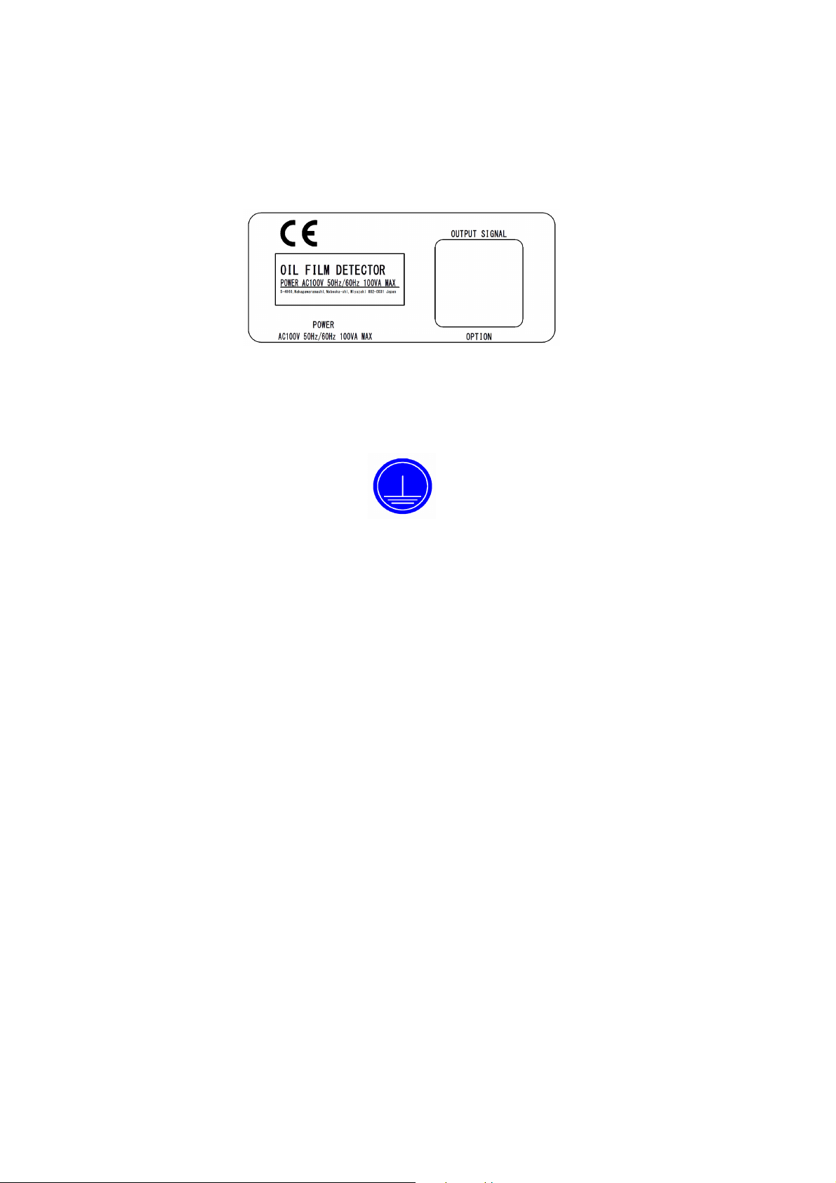
Power supply specification of detector: 100 V AC 10, 50 Hz to 60 Hz.
Install the protection equipment on the power supply.
Avoid supply from the power with noise or large voltage fluctuation.
Provide a safety countermeasure such as a breaker.
Do not connect the shield line on the receiving side.
To extend the signal/contact output cable, use a cable with shield to provide transition
wiring.
Do not ground the terminal [S] of the signal/contact output cable without inserting an
isolator; otherwise, it may result in a failure of detector.
Confirm the wiring confirmation and the power-supply voltage when you complete
construction (100 V AC 10).
Execute it with 250 V DC when you examine the insulation voltage.
When operation without exchanging the optical lock screws, normal detection cannot be
done. In addition, it breaks down when continuously using it.
To remove the detector, first confirm that the power is turned OFF, and replace the truss
head screws (three locations) with the lock screws retained. If shipped with the truss head
screws, it may damage the detector due to shock during transportation.
Periodical maintenance and cleaning are necessary to keep performance well.
If the dirt is hard to be removed, use a neutral detergent.
Do not use an organic detergent such as thinner.