manuals.online logo
Brands
  1. Home
  2. •
  3. Brands
  4. •
  5. Fike
  6. •
  7. Security Sensor
  8. •
  9. Fike 203-0003 User manual

Fike 203-0003 User manual

26-0350 Issue 11
General Description
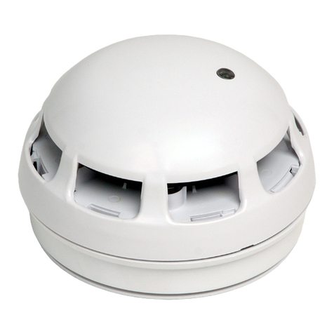
The Multipoint is a plug-in type smoke detector that utilises a photo-electric sensing
chamber to make a measurement corresponding to smoke density. The device also
incorporates a thermistor sensing circuit to allow for accurate heat measurement. These
elements allow the device to be configured to a smoke, heat or combined setting. Digital
communication technology to the control panel is implemented allowing for accurate data
transfer at high transmission speeds. This device is only compatible with the Sita200plus,
Duonet and Quadnet ranges of control panels and may also incorporate a sounder
(ignore all references to sounders if your device has no sounder).
Before Installation
The detector must be installed in compliance with the control panel installation manual. The installation must also
meet the requirements of any local authority. For maximum performance the detector should be installed in
compliance to BS5839 Pt1 : 2002 + A2 : 2008.
Spacing
Fike recommends spacing detectors in accordance with BS5839 Pt1. Due to the effects of IR and possible
magnetic interference, detectors should not be fitted any closer than 500mm (preferably 1000mm) to a light fitting or
any other source of IR or EMI. In addition to this recommendation the device should be mounted so that the
indication LED is facing towards the light source. For more specific information regarding detector spacing,
placement and special applications please refer to BS5839 Pt1 : 2002 + A2 : 2008.
Detector Installation
Fix the base in a suitable position using the two screw slots provided, remembering to allow enough cable length for
termination. All wiring must be installed in compliance with the recommendations laid out by BS5839 Pt1 : 2002 as
well as any special recommendations documented in the control panel installation manual. The cabling used
should be of a 2-core 1.5mm2screened, fire resistant type, and is to be wired in the form of a screened 2-
core loop returning to the control panel. The use of spurs on this system is not permitted. Cables may be
terminated into the connectors mounted in the base, as shown below. Care should be taken when terminating
devices to ensure all cables are correctly sleeved and connections are secure. Improper connections will prevent a
system from responding properly in the event of a fire.
Terminal
Description
SCRN
Screen
0V
Remote LED -ve
AUX +ve
Auxiliary +ve
AUX -ve
Auxiliary 0V
+ve Out
Loop +ve OUT
0V Out
Loop -ve OUT
0V In
Loop -ve IN
+ve In
Loop +ve IN
S +ve
Not Used
The Loop +ve (positive) IN and the Loop +ve (positive) OUT connections are split within the base. For cable
continuity readings at the commissioning stage the supplied link must be fitted. Please remember that all high
voltage testing must be carried out before the installation of the electronics, otherwise the electronics will be
damaged. Please also note that the SCRN terminal should only be connected to the loop screen and NOT the
building earth.
INSTALLATION AND MAINTENANCE INSTRUCTIONS
203-0003 Sita Multipoint Detector and
203-0001 Sita Multipoint Detector / Sounder
AUX +ve
OV
SCRN
+ve Out
AUX -ve
0V Out
0V In
+ve In
S +ve
26-0350 Issue 11
Once all testing has been carried out on the cabling and continuity & insulation has been proven, the Multipoint
unit may be assembled.
Before installing the head remember to note the serial number of the device (located on the electronics module) on
to your drawings or configuration sheets to enable you to prove its location later. The address allocation for the
device is carried out automatically by the control panel whilst in initialisation mode, so addresses do not need to be
set manually. See the system Installation and Operating Instructions for further details.
The Multipoint unit may then be assembled. To insert the Electronics Module, locate the pins and gently push it
home.
The Optical Chamber may then be fitted. Locate the plastic guides into the base and gently twist clockwise until the
unit locks in place. Remember not to force this item: if the Electronics Module is correctly located then the Optical
Chamber should locate with very little force. The Optical Chamber may be removed with the Head Removal Tool.
Tamper Resistance and Head Removal
The Multipoint detector incorporates a tamper resistant locking mechanism that
prevents its removal from the base without the use of a special tool. To remove
the device the tool should be attached over the detector and turned anti-clockwise
allowing the detector to be removed from the base.
If required the Electronics Module may be removed
by inserting the key into the triangular slot adjacent
to the LED and then pulling to ease the Module out.
Do not pull on the optical transmitter and receiver
pair as you may misalign them.
Device Settings
The detection and sounder modes may be configured using the relevant panel software configuration package.
Type
Description
Detection Off:
OFF
No smoke or heat detection
Smoke Modes:
SM1
Highly thermally enhanced optical detector. Used where ionization detectors are normally fitted,
especially where there are high ceilings or a risk of free burning fires.
SM2
Thermally enhanced optical. General purpose smoke detector, to be used where optical detectors are
normally fitted, where there is a risk of a smouldering fire and for escape routes.
SM3
Thermally enhanced optical with smoke pulse rejection. Used where optical detectors are normally
used in positions exposed to brief concentrations of water vapour or smoke e.g. from a bathroom,
kettle, etc.
Heat Modes:
HM1
Rate of rise to 58oC. Used where a standard rate of rise detector would be fitted, e.g. not kitchens.
HM2
Low fixed temperature 58oC. Used where a standard fixed temperature heat detector would normally
be fitted, e.g. suitable for domestic kitchens, etc.
HM3
High fixed temperature 90oC. Used where a high fixed temperature heat detector would normally be
fitted, e.g. suitable for boiler rooms, commercial kitchens, etc.
Sound Patterns
SP0
Sounder off
SP1
Single tone, 970 Hz continually
SP2
Pulsed UK alert signal, 970 Hz 1s on, 1s off
SP3
Dual tone UK evacuate signal, 970 Hz 0.25s, 800 Hz 0.25s
SP4
Sweep up, 800 Hz to 970 Hz over 1s
SP5
Slow whoop up, 500 to 1200 Hz over 3s, 0.5s off
SP6
Sweep down, 1200 Hz to 500 Hz over 1s
SP7
Dual tone French warble, 550 Hz 0.1s, 440 Hz 400ms
NOTE
Sound Patterns SP4 and SP6 are not compatible with the detector I/O facility
Sound Volume:
L/M/H
Low, medium and high settings are available. See the Control Panel Engineering and Commissioning
Instructions for further details
ELECTRONICSMODULE &
REMOVALKEY
OPTICALCHAMBER& HEAD
REMOVALTOOL
26-0350 Issue 11
Auxiliary Input / Output
Where Input or Output functionality is required other than at the control panel, it is recommended that a separate
Sita Loop I/O Module is fitted to the addressable loop as a dedicated I/O module. Where this is not possible, a
limited auxiliary I/O facility is available from the detector via the auxiliary I/O terminals with the addition of a separate
Sita Multipoint Boxed Auxiliary I/O Module (Fike part no. 803-0005) or Sita Multipoint Base Auxiliary I/O Module
(Fike part no. 803-0003). Either an input or an output may be used or controlled respectively through the additional
I/O module which shares the address of the detector to which it is connected. Please see the relevant panel
programming manual for details of the options available for different modes of operation. Note that the detector
auxiliary I/O feature can only be used with the Sita Multipoint Boxed or Base Auxiliary I/O Module. No other
input/output components or equipment may be connected directly to the detector otherwise damage may occur.
Note also that sound patterns SP4 and SP6 may not be used if the detector I/O facility is used.
Remote LED
The remote LED terminals may be used to connect a separate external LED unit (Fike
part no. 600-0092) to the detector that will activate only when the device to which it is
connected enters an alarm condition. The Fike LED unit incorporates the necessary 10k
Ohm current limiting resistor. No other components or equipment may be connected to
the detector remote LED terminals. Connection of other components or equipment may
damage the detector.
Head Contamination Warning
Warning of head contamination is in two stages. Firstly in the form of a ‘Quiescent optical level high or low’ event
recorded into the event log and fault or warnings list (depending on the control panel being used), and secondly in
the form of a ‘Smoke sensor failed; signal high event, recorded into the event log and fault list.
If the smoke detection mode is set to SM0 (off) the head contamination may still be monitored at the detector
depending on the smoke mode, but not by the panel. If contamination is present then the result will be an LED flash
every five seconds at the detector, but the panel will show no fault. Thus, if a device is being re-programmed to re-
enable a smoke detection mode which has been turned off, check the LED status of the device first and ensure that
a clean optical chamber is present. If this is not checked and the smoke detection mode is re-enabled, the device
could signal a fire alarm when re-configured.
Replacing Contaminated Optical Chambers
When an optical chamber becomes contaminated we recommend replacing it with a new replacement item.
Cleaning an old chamber will not give satisfactory results and the reassembly may very easily result in misalignment
of the optical path.
Simply remove the old optical chamber with the head removal tool and replace with a new unit. Once the unit has
been replaced the detector will automatically re-calibrate the optical level for the new chamber
Replacing Multipoint Electronics
If an electronics module requires replacement after the system has been programmed and tested then proceed as
follows:
Stop the loop at the control panel before replacing the module with a new one, noting its serial number onto the
configuration sheets. Initialise the loop from the control panel and re-configure the loop devices using the Re-config
command. This will send the programmed settings from the control panel to the loop devices. The panel should
then be reset and the device tested for all programmed modes of operation.
Testing
Due to the fact that the smoke detection modes are all ‘thermally enhanced’, it may be noticeable that on test the
devices respond more slowly than may be expected. This is perfectly normal and is due to the fact that during a
smoke test there is no additional heat present to cause the sensitivity to be enhanced.
Please note some makes of heat detector test equipment will not operate with these devices due to the position of
the thermistor.
26-0350 Issue 11
Technical Data
Dimensions: Diameter 105mm
Depth 62mm
Operating temperature: -10oC to +50oC
Voltage Range: 24 to 42V DC
LED Indication: Normal 50ms on / 20s interval
Fault 0.1ms on / 5s interval
Fire 50ms on / 400ms interval
Flammability UL94-V2
IP Rating IP 21C
System Compatibility: MPS - Sita200plus V2.00 onwards.
MP - Sita200plus V2.30 onwards.
Duonet and Quadnet V1 onwards.
PRODUCT DESCRIPTION
VOLUME LEVEL (dB)
Type
Product
Code
Name
Low
Medium
High
MP
203 0003
Multipoint Mk3 (25/11/09 Onwards)
-
-
-
MPS
203 0001
Multipoint with Sounder Mk3 (25/11/09 Onwards)
65+
83
88
LOOP CURRENT (mA)
Type
Product
Code
Name
Quiescent
SP0 - Off
Low
Medium
High
MP
203 0003
Multipoint Mk3 (25/11/09 Onwards)
0.12
0.96
-
-
-
MPS
203 0001
Multipoint with Sounder Mk3 (25/11/09 Onwards)
0.12
1.00
1.48
4.03
5.84
BATTERY CURRENT (mA)
Type
Product
Code
Name
Quiescent
SP0 - Off
Low
Medium
High
MP
203 0003
Multipoint Mk3 (25/11/09 Onwards)
0.12
2.00
-
-
-
MPS
203 0001
Multipoint with Sounder Mk3 (25/11/09 Onwards)
0.12
2.00
3.01
8.37
12.04
DLU RATING
Type
Product
Code
Name
SP0 - Off
Low
Medium
High
MP
203 0003
Multipoint Mk3 (25/11/09 Onwards)
1
-
-
-
MPS
203 0001
Multipoint with Sounder Mk3 (25/11/09 Onwards)
1
1.5
4.5
6
N.B. All specified volume and current readings, unless otherwise stated are taken using sound pattern SP3.
Technical Support
Contact your supplier for technical support on this product.
Due to the complexity and inherent importance of a life risk type system training on this equipment is essential, and
commissioning should only be carried out by competent persons. Fike cannot guarantee the operation of any
equipment unless all documented instructions are complied with, without variation. This unit complies with the EMC
directive.
Fike’s policy is one of continual improvement and the right to change a specification at any time without notice is
reserved. Whilst every care has been taken to ensure that the contents of this document are correct at time of
publication, Fike shall be under no liability whatsoever in respect of such contents. E&OE.

This manual suits for next models

1

Other Fike Security Sensor manuals

Fike CEREX User manual

Fike

Fike CEREX User manual

Fike FIK-W-PHOTO User manual

Fike

Fike FIK-W-PHOTO User manual

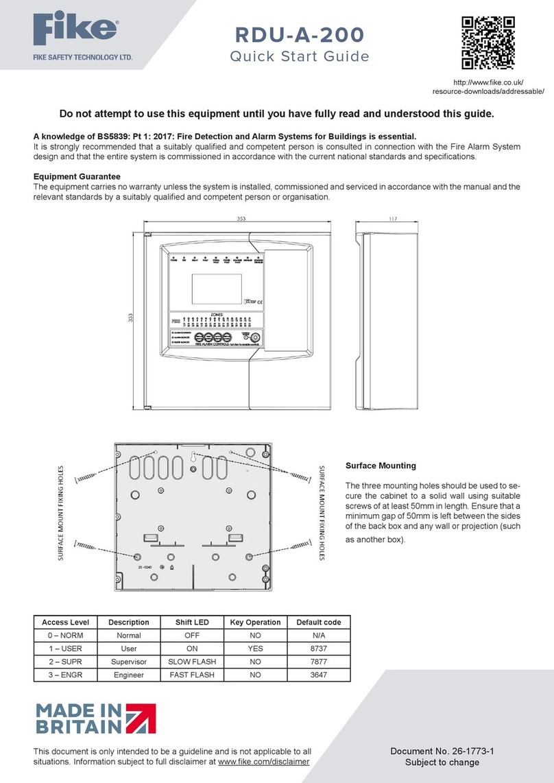
Fike RDU-A-200 User manual

Fike

Fike RDU-A-200 User manual

Fike FIK-UV-IR-HD Series User manual

Fike

Fike FIK-UV-IR-HD Series User manual

Fike FIK-IR3-HD User manual

Fike

Fike FIK-IR3-HD User manual

Fike FIK-RA1000R Technical manual

Fike

Fike FIK-RA1000R Technical manual

Fike Twinflex Multipoint 202-0003 User manual

Fike

Fike Twinflex Multipoint 202-0003 User manual

Fike 323-0001 User manual

Fike

Fike 323-0001 User manual

Fike 60-1039 User manual

Fike

Fike 60-1039 User manual

Fike FIK-IR3-AS25 User manual

Fike

Fike FIK-IR3-AS25 User manual

Fike Sita User manual

Fike

Fike Sita User manual

Fike FIK-IR3-H2 User manual

Fike

Fike FIK-IR3-H2 User manual

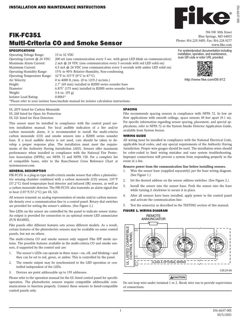
Fike FIK-FC351 User manual

Fike

Fike FIK-FC351 User manual

Fike FIK-RA100 Technical manual

Fike

Fike FIK-RA100 Technical manual

Fike FIK-W-PULL-DA User manual

Fike

Fike FIK-W-PULL-DA User manual

Fike FIK-2351 User manual

Fike

Fike FIK-2351 User manual

Fike 204-0003 Twinflex Multipoint ASD User manual

Fike

Fike 204-0003 Twinflex Multipoint ASD User manual

Fike VESDA LaserCOMPACT VLC-500 User manual

Fike

Fike VESDA LaserCOMPACT VLC-500 User manual

Fike FIK-IR3-H2-HD User manual

Fike

Fike FIK-IR3-H2-HD User manual

Fike OCELUS Series User manual

Fike

Fike OCELUS Series User manual

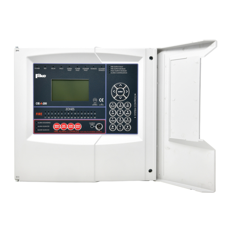
Fike CIE-A-200 User manual

Fike

Fike CIE-A-200 User manual

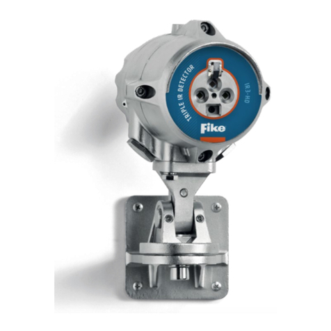
Fike FIK-IR3 User manual

Fike

Fike FIK-IR3 User manual

Popular Security Sensor manuals by other brands

C.Nord CN-Magnetic-Mini installation guide

C.Nord

C.Nord CN-Magnetic-Mini installation guide

PASCO PS-3221 Product guide

PASCO

PASCO PS-3221 Product guide

Tractel LCR Operating and maintenance instructions

Tractel

Tractel LCR Operating and maintenance instructions

D+H TH 4 Original instructions

D+H

D+H TH 4 Original instructions

optrel b330 manual

optrel

optrel b330 manual

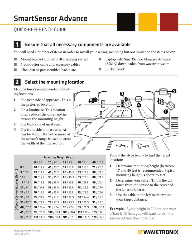
Wavetronix smartsensor advance Quick reference guide

Wavetronix

Wavetronix smartsensor advance Quick reference guide

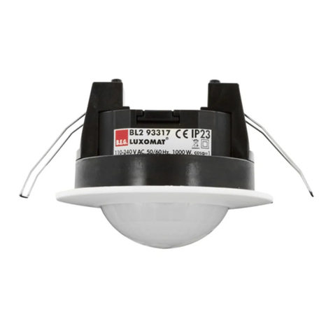
B.E.G. 93386 quick start guide

B.E.G.

B.E.G. 93386 quick start guide

Phoenix ISL SP-ARC user manual

Phoenix ISL

Phoenix ISL SP-ARC user manual

Niko SERVODAN 41-771 user manual

Niko

Niko SERVODAN 41-771 user manual

CARLO GAVAZZI Guardian 1 Original user manual

CARLO GAVAZZI

CARLO GAVAZZI Guardian 1 Original user manual

SGB VL Series Documentation

SGB

SGB VL Series Documentation

Allmatic A1H-U instruction manual

Allmatic

Allmatic A1H-U instruction manual

Rielta Ladoga MK-RK version 2 installation guide

Rielta

Rielta Ladoga MK-RK version 2 installation guide

Milwaukee 48-35-1211 Operator's manual

Milwaukee

Milwaukee 48-35-1211 Operator's manual

Heiman HM-715NVS-AC manual

Heiman

Heiman HM-715NVS-AC manual

Bticino HA/HB/L4619 manual

Bticino

Bticino HA/HB/L4619 manual

B.E.G. LUXOMAT LC-Click 140 Installation and operation instruction

B.E.G.

B.E.G. LUXOMAT LC-Click 140 Installation and operation instruction

Protect 1206i user manual

Protect

Protect 1206i user manual

manuals.online logo
manuals.online logoBrands
  • About & Mission
  • Contact us
  • Privacy Policy
  • Terms and Conditions

Copyright 2025 Manuals.Online. All Rights Reserved.