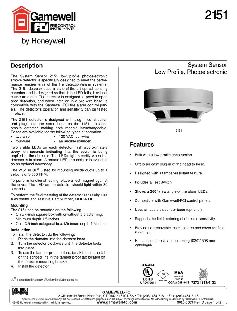
IGM Vega FD 330-4-1 User manual

«IGM-Detector» Co Ltd
Address: 27 Engels Prospect,
building 5, litera A
Saint-Petersburg
194156, Russia,
Tel: 8 (800) 234-66-90
Website: www.igm-pribor.com
1
Flame detector
FD 330-4-1 «Vega»
User manual
MRBP.425241.001-01 UM
2022

MRBP.425241.001-01 UM version 1.1 01.05.2022 FD 330-4-1 «Vega»
2
Contents
Page
1. Introduction..............................................................................................................................3
2. Intended use ............................................................................................................................3
3. Technical specifications.......................................................................................................4
4. Contents of delivery...............................................................................................................6
5. Configuration and operation...............................................................................................7
5.1 Appearance ..........................................................................................................................7
5.2 Overall dimensions ............................................................................................................8
5.3 Construction ........................................................................................................................8
5.4 Principle of operation........................................................................................................8
6. Safety precautions...............................................................................................................10
7. Mounting.................................................................................................................................11
7.1 Mounting location.............................................................................................................11
7.2 Preparation.........................................................................................................................12
7.3 Cable requirements. Cable gland.................................................................................12
8. Detector connection ............................................................................................................13
8.1 Power source requirements...........................................................................................13
8.2 Detector connection.........................................................................................................13
Connecting a detector to digital channel RS-485...............................................................13
5.1 Connection diagrams ......................................................................................................14
9. Commissioning.....................................................................................................................18
Output signals and LED indicators description....................................................................19
9.1 Functionality check..........................................................................................................21
9.1.1 Manual mode.................................................................................................................. 21
9.1.2 Automatic mode............................................................................................................ 22
9.1.3 Detector setup test program...................................................................................... 22
9.2 Factory default...................................................................................................................23
10. Maintenance service........................................................................................................24
11. Troubleshooting................................................................................................................24
12. Packaging...........................................................................................................................25
13. Storage and transportation............................................................................................25
14. Storage ................................................................................................................................25
15. Marking and sealing.........................................................................................................25
16. Warranty..............................................................................................................................26
Appendix A......................................................................................................................................27
Ex-protection drawing..................................................................................................................29
Revision history sheet.................................................................................................................30

MRBP.425241.001-01 UM version 1.1 01.05.2022 FD 330-4-1 «Vega»
3
1. Introduction
This user manual (UM) is intended to describe design, principle of operation and
operating routine of flame detectors «Vega» 330-4-1 (hereinafter FD 330-4-1 «Vega»).
The UM contains basic technical data, guidelines for connection, maintenance service, as
well as other information, necessary for the correct operation, storage and repair of flame
detectors «Vega».
According to GOST R 53325 classification FD 330-4-1 «VEGA»belongs to:
а) by controlled fire sign type –to the flame;
б) by region of the electromagnetic radiation spectrum –infrared;
в) by power supply –powered by a separate wire;
г) by address setting possibility –addressable.
In terms of the functioning quality, FD 330-4-1 "VEGA" meets criteria A in accordance
with GOST R 53325 Appendix B.
Application scope:
explosive and fire hazardous areas of premises and outdoor installations at the
mounting sites of technological equipment of pumping stations of main oil pipelines,
tank farms, loading racks, etc., with the possible occurrence of an explosive and
flammable mixture of vapors of petroleum products, natural gas and other
hydrocarbons
explosive and fire hazardous facilities of the oil and gas as well as fuel and energy
complexes, including production sites, transport systems and storage facilities in the oil
and gas sector, tanks with oil, oil products, natural gas, etc.;
offshore oil production/refining platforms, ships and vessels;
as a part of fire protection and firefighting installations and complexes.
2. Intended use
FD 330-4-1 «VEGA»is a multi-range detector, responding to infrared (IR) radiation in
three regions of the spectrum.
Flame detector FD 330-4-1 «VEGA»is designed to detect fires of various combustible
materials indoors and outdoors and transmit a fire notification signal to fire alarm control
units, security and fire units and/or automatic fire fighting systems. It can be used both as a
separate device and as part of fire and security alarm systems.
FD 330-4-1 «VEGA»is placed at the process equipment mounting locations at oil and
gas production, transportation and storage facilities, in pumping stations of main oil
pipelines, on open areas, offshore platforms and tank farms, loading racks, etc. (electrical
equipment of subgroups IIA, IIB, IIC, IIIA, IIIB, IIIC temperature classes T1 - T6 according
to GOST IEC 60079-14-2013.

MRBP.425241.001-01 UM version 1.1 01.05.2022 FD 330-4-1 «Vega»
4
3. Technical specifications
Housing material
- Aluminium
- Marine grade stainless
EX-marking
1 Ex d IIC T6…Т4 Gb Х; Ex tb IIIC T85°C
…135°C Db Х
Sign Х, following the ex-marking, means that
while mounting a detector you should use a
cable gland and a plug, certified according
to TR CU and having a marking according to
certificate.
Protection
IP 66/IP68
FD 330-4-1 «VEGA»overall dimensions
(with a mounting bracket) not more than,
mm
Ø266×166×99
FD 330-4-1 «VEGA»weight (with a
mounting bracket) not more than, kg
- 3,5 (aluminium),
- 6,0 (stainless)
Cable gland type
M 20
Ambient temperature range
-60 …+125 C for temperature class Т4
-60 …+90°C for temperature class Т5
-60 … +75 C for temperature class Т6
Ambient temperature range according to
transportation conditions
-50° C … +50°C
RH
Up to 95% (short-term exposure to 100%
humidity is allowed)
Supply voltage
Nominal: 24 VDC;
Range: 18 …32 VDC
FD 330-4-1 «VEGA»power consumption
Stand-by mode –not more than 2 VA,
Alarm mode –not more than 3 VA.
With heating on –not more than 5,8 VA
FD 330-4-1 «VEGA»viewing angle, not
less than
120°
FD 330-4-1 «VEGA»responds
а) to radiation, generated by test sources
TP-5 иTP-6 according to GOST R 53325
Appendix A at a distance of at least 25 m
(detectors of the 1st class);
б) to radiation, created by test radiation
source.
Output signals
- analogue signal: 4..20 mA
- HART-interface
- digital signal in RS-485 standard with
Modbus RTU interface;
- actuation of relay contacts «Fire» and
«Failure».
FD 330-4-1 «VEGA»response time on
test flames TP-5 and TP-6 at a distance of
25 meters
not more than 5 s
Seismic resistance
FD 330-4-1 «VEGA»are earthquake-
resistant till 9 points according to MSK-64 at
the installation level above the zero mark up
to 10 m in accordance with GOST 30546.1-
98.
MTBF
Not less than 100000 h
Specified lifetime
15 years

MRBP.425241.001-01 UM version 1.1 01.05.2022 FD 330-4-1 «Vega»
5
Shelf life and conservation of detectors
in the manufacturer's packaging
10 years
Warranty storage period
6 months since manufacturing
Warranty life
- 18 months from the day of commissioning;
- not more than 24 months since
manufacturing.
Exposure to sinusoidal vibration
group V2 GOST R 52931-2008,
corresponding to operation conditions
group F3 GOST R 52931-2008,
corresponding to transportation conditions
Resistance to atmospheric pressure
according to GOST R 52931-2008.
Group R1
Climatic category according to GOST
15150-69.
Boreal climate class 1
Seismic resistance according to GOST
30546.1-98
the impact of earthquakes with an intensity
of 9 points according to MSK-64 at an
installation level above the zero mark up to
10 m
Immunity to direct mechanical impact
with an energy of at least
1,9 J
Resistant to single shock pulses of a
half-sine waveform with peak
acceleration
with a pulse duration within
50 m/s2
10 - 20 ms
Immunity to nanosecond electrical
impulses propagating in the power
circuit and in the output circuits
Severity degree 4 according to GOST R
53325 Appendix B
Resistance to exposure to electrostatic
discharges of at least, kV:
contact –8;
air –15
Immunity to RF electromagnetic fields
with parameters
root-mean-square value of electromagnetic
field strength with amplitude modulation
depth of 80%, frequency 1 kHz, not less
than, V/m:
frequency range 0,1 …150 MHz –10;
frequency range 150 …500 MHz –5.

MRBP.425241.001-01 UM version 1.1 01.05.2022 FD 330-4-1 «Vega»
6
4. Contents of delivery
Package includes:
Name
Identification
Number
Flame detector
FD 330-4-1 «VEGA»
1
User manual
MRBP.425241.001-01UM
1 in a set
Datasheet
MRBP.425241.001-01 DS
1
Approval documentation
(certificates of
conformity, declarations
of conformity, permits
etc.)
-
1 package in a set,
delivered on a CD.
Paper copy –on
request.
Magnetic key
-
1 for 10 devices, but not
less than 1 in a set
Cable gland
-
On request
End plugs
-
On request
Sunshield
-
On request
Magnetic key allows to perform operability check in conditions of standard mounting
without disconnection from the external actuating alarm system.
Sunshield - protects the optical elements of the sensors from the adverse effects of the
environment at their mounting location.
The test radiation source is designed to test the detectors’ operability without
dismounting the latter from their workplaces.
Cable gland, designed for safe cable entry while mounting. Specify the model of the cable
gland when ordering. Not included in the delivery set, delivered on request.
End plug, is installed in a free hole for cable entry, to ensure the tightness and explosion
resistance of the gas detector. Specify the model of the end plug when ordering. Not
included in the delivery set, delivered on request.

MRBP.425241.001-01 UM version 1.1 01.05.2022 FD 330-4-1 «Vega»
7
5. Configuration and operation
5.1 Appearance
Figure 1 –FD 330-4-1 «VEGA»appearance

MRBP.425241.001-01 UM version 1.1 01.05.2022 FD 330-4-1 «Vega»
8
5.2 Overall dimensions
Figure 2 - Overall dimensions of the detector with a mounting bracket
5.3 Construction
The detector housing is a flameproof enclosure, inside which all detector devices are
located, including sensitive elements that convert the electromagnetic radiation of the flame
into an electrical signal, electronic amplifiers and filters, digital-to-analog converters, a
microprocessor, display elements, optical elements for checking the operability of channels.
5.4 Principle of operation
The IR sensor, when a flame is detected, converts electromagnetic radiation into an
electrical signal. Signals in digital form are processed in the microcontroller according to a
given algorithm to increase the reliability of the alarm output. The program highlights the
useful signal from the background. As a result of signal processing, a decision is made on the
formation of output signals: analog current output 4.20 mA, digital output in RS-485 standard
with Modbus RTU interface, “FIRE” relay contacts, “FAILURE”relay contacts.
FD 330-4-1 «VEGA»detector is equipped with a special self-testing function, that
performs correct operation check automatically every 30 minutes. It does not require the use
of an external control source of radiation (test lamp). Successful completion of the automatic
check does not cause the detector to switch to the ‘‘Fire” mode.
FD 330-4-1 «VEGA»is resistant to false alarm. It doesn’t respond to visual disturbance
sources other than flame, such as electric welding, artificial lighting, sunlight, lightning, high
voltage arc, X-rays and gamma rays, etc.

MRBP.425241.001-01 UM version 1.1 01.05.2022 FD 330-4-1 «Vega»
9
Notice: It is not recommended to operate FD 330-4-1 «VEGA»in places where combined disturbance
may occur (welding + radio station 5 W 100 MHz, welding + device vibration with an acceleration > 10
g). It is not recommended to use radio station in a distance less than 1 m away from FD 330-4-1
«VEGA»under conditions of continuous exposure to radiation from welding.

MRBP.425241.001-01 UM version 1.1 01.05.2022 FD 330-4-1 «Vega»
10
6. Safety precautions
Any person who is familiar with the configuration, has studied this UM, has
been briefed on safety precautions when working with electrical installations
and have an electrical safety qualification group of at least III, including in
hazardous areas, is admitted to operate the flame detector.
FD 330-4-1 «VEGA»must have internal and external groundings and
grounding signs in accordance with GOST21130-75.
It is forbidden to operate the detector if the housing is damaged.
Equipment mounting in pumping stations should be carried out in
accordance with SNiP (construction rules and regulations) 3.05.05-84
"Technological equipment and process pipelines".
Detectors mounting must be carried out with the power supply switched
off.
Detector repair is allowed only to the personnel of the manufacturer's
enterprise or to persons authorized by the manufacturer to carry out repair
work.
FD 330-4-1 «VEGA»mounting at the control object must be carried out
in accordance with the duly approved project for the system placement, which
includes FD 330-4-1 «VEGA». Install detectors according to the project, while
FD 330-4-1 «VEGA»mounting it is necessary to follow:
Chapter 7.3 of the Electrical Installation Code;
Chapter 3.4 of the Operational Code for Electrical Installations
(OCEI);
Safety Rules for Operation of Customers' Electrical Installations;
This UM and maintenance documentation for co-used technical
equipment.
Electrical connections must be made in accordance with point
8Ошибка! Источник ссылки не найден..

MRBP.425241.001-01 UM version 1.1 01.05.2022 FD 330-4-1 «Vega»
11
7. Mounting
7.1 Mounting location
For the correct mounting of the detector, the following factors must be taken into
account:
The location of the detectors must ensure unobstructed control of the entire
protected area;
While detector’s positioning and targeting take into account the distance of
action and the viewing angle of the device;
Notice: Recognized that FD 330-4-1 «VEGA»has the highest sensitivity along
the central axis, which should be oriented to the place of a possible fire (Figure
1);
Wrong orientation of the detector
Correct orientation of the detector
Figure 3 –Installation relative to the horizon.
It is necessary to visually estimate the area (viewing angle) controlled by the
detector. To do this, you can use the viewing angle indicator, which simplifies
the process of orienting the sensors while mounting in the field.
While mounting the detector should be oriented in such a way as to avoid direct
illumination from radiation powerful sources (sun, projector, etc.)
If there is a danger of mechanical damage to the detector, a protective structure
must be provided that does not intervene its performance and fire detection
efficiency;
Central axis direction
Central axis direction

MRBP.425241.001-01 UM version 1.1 01.05.2022 FD 330-4-1 «Vega»
12
Availability of a sufficient number of detectors to protect the controlled area;
The detector must be mounted on a rigid surface that is not subject to vibrations;
The detector must be easily accessible for periodic maintenance service;
While mounting take measures to prevent moisture from getting into the
electrical connections or components of the detector. Ensuring moisture
protection is necessary to keep the device in operation.
7.2 Preparation
Before FD 330-4-1 «VEGA»mounting a visual inspection is carried out. It needs to pay
attention to:
1) FD 330-4-1 «VEGA»ex-marking and a warning label;
2) zero damages;
3) presence of all the fasteners (bolts, nuts, washers) in accordance with FD 330-4-
1 «VEGA»site placement project;
4) presence and integrity of the connecting wires (coming out of FD 330-4-1 «VEGA»
insulation;
5) presence and integrity of the seal on the housing of FD 330-4-1 «VEGA».
6) It is recommended to connect FD 330-4-1 «VEGA» analogue outputs located in
the hazardous area with an external device located in the non-explosive area using a control
armored cable of the КВБбШв4х1,5 brand according to GOST 1508-78. The КВБбШв cable
can be used in hazardous areas of any class, including indoors, outdoors, in channels,
tunnels, ground (trench) in an aggressive environment, in places exposed to stray currents.
7) While FD 330-4-1 «VEGA» mounting it is necessary to check the condition of the
ex-proof parts subjected to disassembly for compliance with the requirements of the EX
protection drawing (appendix B).
8) Removable parts should fit as closely to the housing as possible.
9) The cable sealing on the cable gland must be carried out in every manner, since
the explosion-resistance of the input converter depends of this.
10) The external grounding conductor must be carefully stripped, and its connection
to the grounding clamp must be protected from corrosion by applying grease.
11) Upon mounting completion, the grounding device resistance must be checked
and must not exceed 4 Ohm.
7.3 Cable requirements. Cable gland
It is recommended to connect FD 330-4-1 «VEGA» analogue outputs located in the
hazardous area with an external device located in the non-explosive area using a control
armored cable of the КВБбШв4х1,5 brand according to GOST 1508-78. The КВБбШв
cable can be used in hazardous areas of any class, including indoors, outdoors, in
channels, tunnels, ground (trench) in an aggressive environment, in places exposed to
stray currents.
Use certified cable glands M20 while mounting.
The cable sealing on the cable gland must be carried out in every manner, since the
explosion-resistance of the entry compartment depends of this.
Notice: If it is necessary to connect piping to a cable gland with a ¾’ NPT thread, the
connection is made using a transitional threaded sleeve:

MRBP.425241.001-01 UM version 1.1 01.05.2022 FD 330-4-1 «Vega»
13
8. Detector connection
8.1 Power source requirements
Before connection it is necessary to:
- Calculate the total power consumption rate of the gas detection system in watts,
taking into account cold start.
- Select a power source with the appropriate power for the calculated load.
- Make sure the selected power source provides a regulated 24 VDC output voltage
for the entire system, taking into account allowable ripples. It is recommended to use
of a battery backup power supply to improve system reliability.
Notice: If it is required to be able to turn off the power supply, then a separate method
of turning it off must be provided.
8.2 Detector connection
To connect the detector:
-fix the mounting bracket at the FD 330-4-1 «VEGA» workplace, install a base on it
and fix it with a screw and a lock nut. The detector with a mounting bracket and its overall
dimensions are shown in figure 2;
-separate the base with cable gland from the detector housing;
-install the connecting cable in the cable gland исоединить проводники с
соответствующими клеммами,and connect the conductors to the corresponding terminals
located on the backplane:
Figures 4 and 5 show examples of connecting the detector to fire alarm control panels;
Figures 6 and 7 show diagrams of connecting the detector to fire alarm control panels
in the analogue signal using and digital output using mode;
Figures 8 and 9 show diagrams of connecting two detectors to fire alarm control system
via RS-485 interface with and w/o terminal box;
-install the FD 330-4-1 «VEGA» housing on the base and tighten the 3 screws;
-turn the detector for correct targeting;
-after applying power to the detector, it is necessary to check whether the LED
indicator on the FD 330-4-1 «VEGA» front is illuminated with constant yellow light for 3
seconds. After 3 seconds, the LED indicator lights up with a flashing yellow light for 7-8
seconds, after which the detector self-test begins (three test lamps flash three times), then at
the end of the initial test –a continuous glow of green.
Detector connection to RS-485 digital channel
1. It is recommended to connect the detectors to the bus via a terminal box. Detectors
connection to a terminal box is carried out by a cable with a recommended length of
not more than 0,5m. Cable must meet the cable gland requirements on the FD 330-4-
1 «VEGA» housing and terminal box. For the connection from terminal box to the bus
an armored cable with pairs of shielded twisted pairs can be used.
2. For the correct power supply network organization note that the supply voltage at the
terminals of the devices must be not less than 18 V and not more than 32 V, taking
into account the FD 330-4-1 «VEGA» consumption.
3. The information network organization must be carried out in a way that the voltage drop
on the –24 V wire between the central processor and the detector does not exceed 8
V.

MRBP.425241.001-01 UM version 1.1 01.05.2022 FD 330-4-1 «Vega»
14
4. It is recommended to connect the detectors in a branch line from the main interface line.
Branches should be formed by installing repeater-splitters with galvanic isolation of the
type at the nodal points of the line. Each branch must serve a separate tank. Extension
of the main line beyond 1200 m must be carried out by inserting an interface repeater into
the line.
5. It is advisable to power the FD 330-4-1 «VEGA» according to the beam scheme - each
tank has its own cable.
Allowable line length is determined by the formula:
L(km) = 25 ΔU(V) S (mm2) / Imax(mA),
where ΔU(V) –allowable line voltage drop;
Imax(mA) –max current consumption;
(Imax(mA)FD 330-4-1 «VEGA» = 150 mA N(pcs.)
Notice: FD 330-4-1 «VEGA» digital output protocol parameters are shown in Appendix A.
5.1Connection diagrams
Figure 4 –Connection diagram for an explosion-proof detector EEx

MRBP.425241.001-01 UM version 1.1 01.05.2022 FD 330-4-1 «Vega»
15
Figure 5 –Connection diagram for an ultra-explosion-proof detector EEx de.
Figure 6 –Connection diagram for a detector with uninsulated output 4-20 mA

MRBP.425241.001-01 UM version 1.1 01.05.2022 FD 330-4-1 «Vega»
16
Figure 7 –Connection diagram for an explosion-proof detector
ЕЕх via RS-485 interface
Figure 8 –Connection diagram for two explosion-proof detectors EEx via RS-485 interface

MRBP.425241.001-01 UM version 1.1 01.05.2022 FD 330-4-1 «Vega»
17
Terminal box
Figure 9 –Connection diagram for two detectors and a digital channel RS-485 via terminal
box

MRBP.425241.001-01 UM version 1.1 01.05.2022 FD 330-4-1 «Vega»
18
Notice: 250 Ohm is necessary to ensure the correct operation of the HART interface, in
case of 4-20 mA controller low resistance, it is not necessary to install resistance at the FD
330-4-1 «VEGA» output, it can be installed at the controller input.
Figure10 –Three-wired connection diagram FD 330-4-1 «VEGA» using 4-20mA and HART
Notice: 250 Ohm is necessary to ensure the correct operation of the HART interface, in
case of 4-20 mA controller low resistance, it is not necessary to install resistance at the FD
330-4-1 «VEGA» output, it can be installed at the controller input.
Figure 11 –Four-wired FD 330-4-1 «VEGA» connection diagram using 4-20mA and HART
9. Commissioning
PROHIBITED:
1 OPERATION OF THE DETECTORS IN CONDITIONS AND MODES
DIFFERENT FROM THOSE, MENTIONNED IN THIS UM!
2 OPERATION OF THE DETECTORS WITH DAMAGED ELEMENTS, SEALS
AN OTHER MALFUNCTIONS!

MRBP.425241.001-01 UM version 1.1 01.05.2022 FD 330-4-1 «Vega»
19
3.OPEN THE DETECTORS IN A HAZARDOUS AREA WITH POWER ON
Detector’s housing must be grounded.
Output signal and LED indicators description
FD 330-4-1 «VEGA» generates the following output signals:
-analogue signal with the following meanings:
a) (2 ± 0,1) mA –«Failure»;
b) (4 ± 0,1) mA –«Standard»;
c) (18 ± 0,1) mA –«Fire»;
d) (4.1 ± 0,1) mA –«Testing».
-digital signal via standard communication channel RS-485 with MODBUS protocol;
- actuating of the «dry» contacts of two relays «Fire» and «Failure». Relays are
designed for switching current 1 A at a voltage of 30 VDC.
FD 330-4-1 «VEGA» is equipped with LED indicators, displaying the current operation
mode of the detector.
Table 1 lists output signals, states of the relay contacts and indicator LEDs for FD
330-4-1 «VEGA» different states. Table 1
№
FD 330-4-1
«VEGA» state
«Fire»relay
contacts state
«Failure»relay
contacts state
Output
signal, mA
LED indicators state
1
No supply
voltage
Open
Open
0
Off
2
After switching
on during up to
45 seconds
Open
Open
2
First 5 seconds
continuous, then
flashing yellow glow
3
Dirty optics or
presence of an
object at a
distance of 5-
10 cm from the
entrance
window
Open
Open
2
Periodic switching of
the glow from yellow
to green
4
Failure
Open
Open
2
Continuous yellow
glow
5
Standard
Open
Closed
4
Continuous green
glow
6
Warning
Open
Open
4
Periodic switching of
the glow from green
to red (once a
second)
7
Fire
Closed
Closed
18
Continuous red glow
8
Testing
Open
Closed
4,1
Depending on the
presence of radiation,
one of the above
modes is possible
9
Checking mode
(with a
magnetic key
on)
Open
Open
2
Depending on the
previous mode the
indication remains
It is possible to fix the output signal "Fire" after the end of the alarm cause.

MRBP.425241.001-01 UM version 1.1 01.05.2022 FD 330-4-1 «Vega»
20
It is possible to change the sensitivity and signal processing time to reduce the effect of
interference when identifying a fire or a nearby location of the alleged fire site («far/near» and
«fast/slow»modes).
Table of contents
Other IGM Security Sensor manuals
Popular Security Sensor manuals by other brands

FORTEZA
FORTEZA FORTEZA-300 user manual

Hotron
Hotron KABUTO user manual

YOSensi
YOSensi YO Airflow Pro user guide
System Sensor
System Sensor B110LP Installation and maintenance instructions
Inovonics
Inovonics EE1260 EchoStream Installation and operation manual
Metrohm
Metrohm IC Conductivity Detector manual
