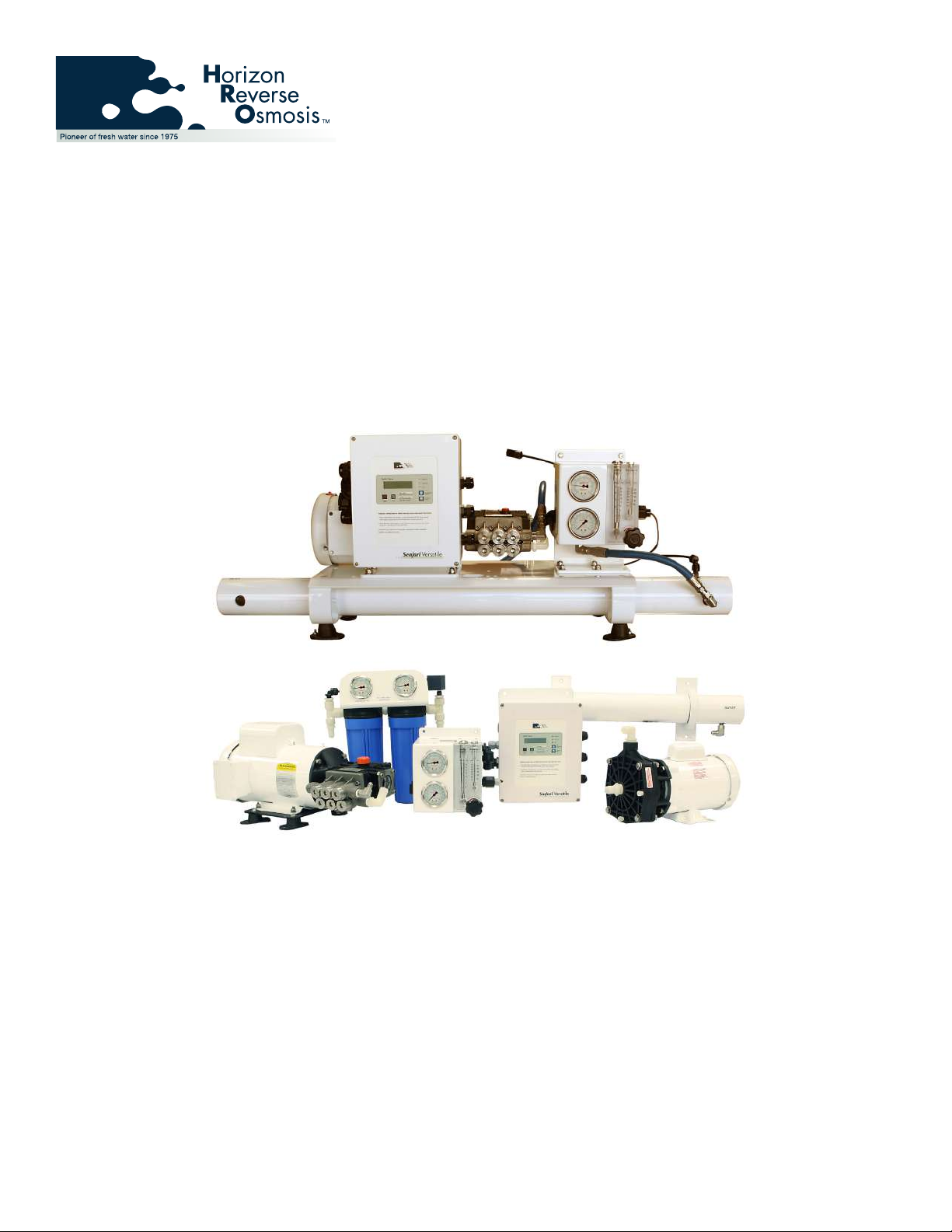
Seafari Versatile 450 - 1800
Page i
PREFACE
Thank you for purchasing an Horizon Reverse
Osmosis Desalination System. Please read this
manual carefully before attempting installation or
operation. A better understanding of the system
ensures optimum performance and longer service
life from the system.
All Horizon Reverse Osmosis desalination systems
are designed and engineered to function as a
complete working unit. Generally speaking, the
performance of each component within the unit is
dependent on the component prior to it and governs
the performance of all components after it. Proper
performance of the system is thus dependent upon
proper operation of every single component within
the system.
The intent of this manual is to allow the operator
to become familiar with each component within
the Horizon Seafari system. By understanding the
function, importance, and normal operation of each
component within each subsystem of the unit, the
operator can readily diagnose minor problems.
Such problems, when they rst develop, usually
require minor maintenance and are easily corrected.
However, left unattended, a problem in one
component aects the rest of the system and leads to
further required repairs.
COPYRIGHT NOTIFICATION
©Copyright HRO Systems 2008 - 2010. All content
included within this manual such as text, graphics,
logos, and images, is the property of HRO Systems
and protected by U.S. & International copyright laws.
The compilation (meaning the preparation,
collection, arrangement, and assembly) of all content
within this manual is the exclusive property of HRO
Systems and protected by U.S. and international
copyright laws.
All software used in the design and manufacture of
the HRO Systems is the property of HRO Systems
and protected by U.S. and international copyright
laws. All computer and logic programming used
in the design and manufacture of the HRO Reverse
Osmosis Desalination System is the property
of HRO Systems and protected by U.S. and
international copyright laws.
The content of this manual and the software,
programming, and graphic designs used in the
design and manufacture of the HRO Systems
Reverse Osmosis Desalination System is for the
purpose of operation, maintaining, and repair of
the HRO Systems Reverse Osmosis Desalination
System. Any other use, including the reproduction,
modication, distribution, transmission,
republication, display, or performance, of the content
within this manual is strictly prohibited.
TERMS AND CONDITIONS
The use of this manual acknowledges acceptance of
the terms and conditions provided herewith and the
agreement to comply with all applicable laws and
regulations pertaining to the use of this manual.
In addition, the use of this manual forms an
agreement that HRO Systems trademarked name
or HRO Systems trademarked logo mark are not to
be used in any form or manner except with HRO
Systems written permission. HRO Systems holds all
rights to its copyrights and trademarks, and to the
material contained in this manual. Any use of such
requires the written permission from HRO Systems.
PATENT INFORMATION
Certain aspects of the HRO Systems Reverse
Osmosis Desalination System are protected by U.S.
and International Patent Laws.
NOTICE OF LIABILITY
The information contained in the manual is
distributed on an “As is”basis, without warranty.
While every eort has been taken in the preparation
of this manual, HRO Systems shall not be held liable
with respect to any liability, loss, or damage caused
by the instructions contained in this manual. The
information contained in this manual is subject to
change without notice.
TRADEMARKS
The HRO Systems logo mark is a U.S. Registered
Trademark and belongs to HRO Systems with all
rights reserved. HRO Systems is a US Registered
trademark of HRO Systems. Seafari™is a trademark
of HRO Systems.