SPX FLOW HANKISON HF Series User manual

HF Series
Compressed Air Filters
Models HF(grade)-12 through HF(grade)-48
FORM NO.: 4011203 REVISION: 10/2015 READ AND UNDERSTAND THIS MANUAL PRIOR TO OPERATING OR SERVICING THIS PRODUCT.
INSTRUCTION MANUAL

General Safety Information
1. Pressurized devices
• Donotexceedmaximumoperatingpressure
indicatedonserialnumbertag.
• Makecertainlterisfullydepressurizedbefore
servicing.
2. Breathing Air
• Airtreatedbythisequipmentmaynotbesuit-
ableforbreathingwithoutfurtherpurication.
RefertoOSHAstandard1910.134forbreathing
airrequirements.
3. Flammable gases
Whilethematerialsofconstructionarecompatible
withmanyammablegases,thefollowingapplica-
tionlimitationsmustbeconsidered:
• Housingmaterialsareslightlyporous.Theprod-
uctmustbeusedinawellventilatedareainthe
absenceofsparksorignitionsources.Donot
useinClass1,Division1,GroupDenvironments.
• Thetypeofarea-forcedexhaustsystemused
(i.e.,highorlowlevel)wouldbedependenton
thegasinvolved.
• Eachapplication(otherthanforairorinertgas)
mustbereviewedtominimizereorexplosion
hazard.
Contents
MODELNUMBERCONFIGURATION.......................... 1
1.0INSTALLATION.................................................... 2
2.0OPERATION....................................................... 5
3.0MAINTENANCE.................................................. 6
DIMENSIONSANDWEIGHTS..................................... 8
WARRANTY.............................................................. 9

1
Grade Identification
Filtergradecanbeidentiedbythethirddigitofthemodelnumber.Inaddition,elementswithafoamoutersleevecan
beidentiedbycolor.
Grade Description Type Outer foam color
11 Mechanical Separator Impaction type separator none
9 Separator/filter Mechanical separator and 3 micron coalescer none
7 General purpose air line filter 1 micron coalescer none
6 Dry Desiccant Afterfilter 1 micron after-filter for desiccant dryers none
5 High efficiency oil removal filter High efficiency (99.99+%) coalescer Red
3 Maximum efficiency oil removal filter Maximum efficiency (99.999+%) coalescer Blue
1 Oil vapor removal filter Activated carbon adsorber Green
Model Number Configuration
HF (1) -(2) -(3) -(4)
1. Filter Grade is indicated in space (1).
2. Housing Number is indicated in space (2).
3. Connection Size is indicated in space (3)
4. Features
D = Internal Automatic Drain Mechanism
P = Differential Pressure Slide Indicator
G = Differential Pressure Gauge Indicator
L = Liquid Level Indicator
S = Corrosion Proof Stainless Steel Element
X = External Drain Adapter
M = Filter Monitor
Example: A Grade 5 high efficiency oil removal filter with a capacity of 100 scfm
and 3/4” NPTF connections, internal drain, filter monitor and liquid level
indicator would be configured as: HF5-24-6-DML
(2) Housing (3) Connection Sizes
Number Capacity
scfm [m3hr] @
100 psig [7 kgf/cm2]
12
16
20
20 [35]
35 [60]
60 [105]
3- 3/8” NPTF or
4- 1/2” NPTF
3B - 3/8” BSP or
4B - 1/2” BSP
24
28
100 [170]
170 [290]
6- 3/4” NPTF or
8- 1” NPTF
6B - 3/4” BSP or
8B - 1” BSP
32
36
250 [425]
375 [640]
8- 1” NPTF or
10 - 1-1/4” NPTF or
12 - 1-1/2” NPTF
8B - 1” BSP or
10B - 1-1/4” BSP or
12B - 1-1/2” BSP
40 485 [825] 16 - 2” NPTF or
20 - 2-1/2” NPTF
16B - 2” BSP or
20B - 2-1/2” BSP
44
48
625 [1060]
780 [1325] 20 - 2-1/2” NPTF 20B - 2-1/2” BSP
(4) Features
D= Internal Automatic Drain
Mechanism
P= Differential Pressure Slide
Indicator
G= Differential Pressure Gauge
Indicator
L= Liquid Level Indicator
S = Corrosion Proof Stainless
Steel Element
X= External Drain Adapter
M= Filter Monitor
(1) Filter Grade
11 - Mechanical Separator
9- Separator/Filter
7- Air Line Filter
6- Dry Desiccant Afterfilter
5- High Efficiency Oil Removal Filter
3- Maximum Efficiency Oil Removal Filter
1- Oil Vapor Removal Filter

2
1.0 Installation
A. Where Used/Air Quality After Filtration
Grade Where used
Solid particle
removal (maximum
size in microns)
Liquid removal
efficiency (at
rated conditions)
Maximum inlet
liquid loading
ppm w/w
Remaining
oil content
ppm w/w
11 Separator - downstream of an aftercooler
Point-of-use - where no aftercooler is installed
upstream
— 95% of water 30,000
bulk liquids
—
9 Separator - downstream of an aftercooler
Point-of-use - where no aftercooler is installed
upstream or as prefilter to refrigerated dryer
3 99+% of water 25,000
aerosols &
bulk liquids
5
aerosols
7 Prefilter -
•PreltertoGrade3&Grade5-highefciency
coalescing filters
Point-of-use - where aftercooler is installed
upstream
1 100% of water 2,000
aerosols
1
aerosols
6 Afterfilter - downstream of a pressure-swing
(heatless) desiccant dryer
•DownstreamofanActivatedCarbonor
Desiccant Tower
1 No liquid should be
present at inlet
No liquid should be
present at inlet
—
5 Prefilter
•Aheadofdesiccantandmembranedryers
Afterfilter
•Downstreamofrefrigerateddryer
•Downstreamofpressure-swing(heatless)
desiccant dryers for finer solid particle removal
•Oilremovalatpoint-of-use
0.01 99.99+% of oil 1,000
aerosols
0.008
aerosols
3 Prefilter - ahead of desiccant and membrane
dryers (use after Grade 7 to reduce liquid and
solids load, prolong element life and ensure
filtration efficiency)
Afterfilter - downstream of refrigerated dryer
0.01 99.999+% of oil 100
aerosols
0.0008
aerosols
1 Afterfilter to Grade 3 & Grade 5 for true oil free
applications
0.01 Removes vapors
only
No liquid should be
present
0.003
vapor
3
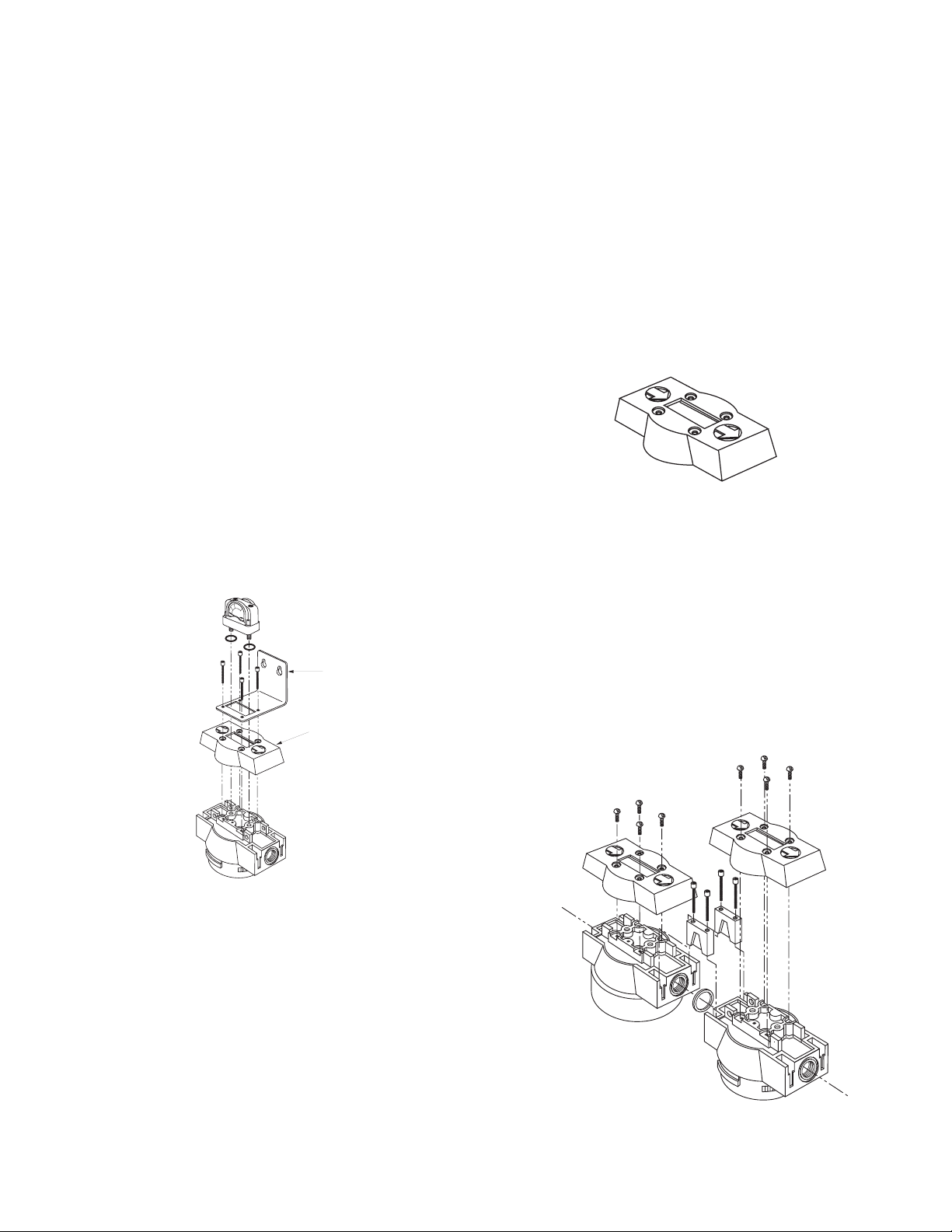
B. Mounting
1. Wallmountingbrackets-Mountbrackettolter
head:
(1) removefour(4)screwsholdingblackplastictop
captolterhead
(2) placebracketonheadoverplasticcap
(3) installscrewssuppliedwithbracket.
2. DifferentialPressureGaugeMountingtoFilterHead
(1) makecertaino-ringsareinplaceonthebot-
tomofthegaugebody.
(2) connectthelowpressuretransmissionbolt
(boltnexttotheREDbandongauge)tothe
gaugeportatthelteroutlet(downstream
sideoflter).
(3) connectthehighpressuretransmissionbolt
(boltnexttoGREENbandongauge)tothe
gaugeportatthelterinlet(upstreamsideof
thelter).
(4) useacoinoraatheadscrewdrivertotighten/
loosenbolts.Thetipwidthofthescrewdriver
shouldbeatleast3/8"inch(9.5mm).Torque
boltsto25+/-5inchoz.DO NOT OVER
TIGHTEN
Wall Mounting
Bracket
Top Cap
Figure 1.1
C. Piping
1. Beforeinstalling,blowoutpipelinetoremovescale
andotherforeignmatter.
2. ThisunithasDRYSEALpipethreads;usepipecom-
poundortapesparinglytomalethreadsonly.
3. Mounting(Grades11,9,7,5,3)-mountsothatinlet
andoutletconnectionsarehorizontal(lterbowl
vertical)toensureproperliquiddrainage.
4. FlowDirection-installsothattheairowisinthe
directionofarrowsonthelterhead.
NOTE:Grade6owsfromoutsidetoinsidethe
element.Allothergradesowfrominsidetoout-
sidetheelement.Observeowarrowsoncap.
5. Directlter-to-lter(modular)connection-Filter
headsmaybejoinedwithoutusingapipenipple
a. Bayonettypeheads-Usetwo(2)modularcon-
nectors,o-ring,andfour(4)socketheadcap
screws(soldaskit)
Removeblackplastictopcap,applygenerous
amountoflubricanttoo-ring,installo-ringin
groove,andinsertconnectors.Screwconnec-
torstoheadusingsocketheadcapscrews.
Figure 1.3
Figure 1.2
4
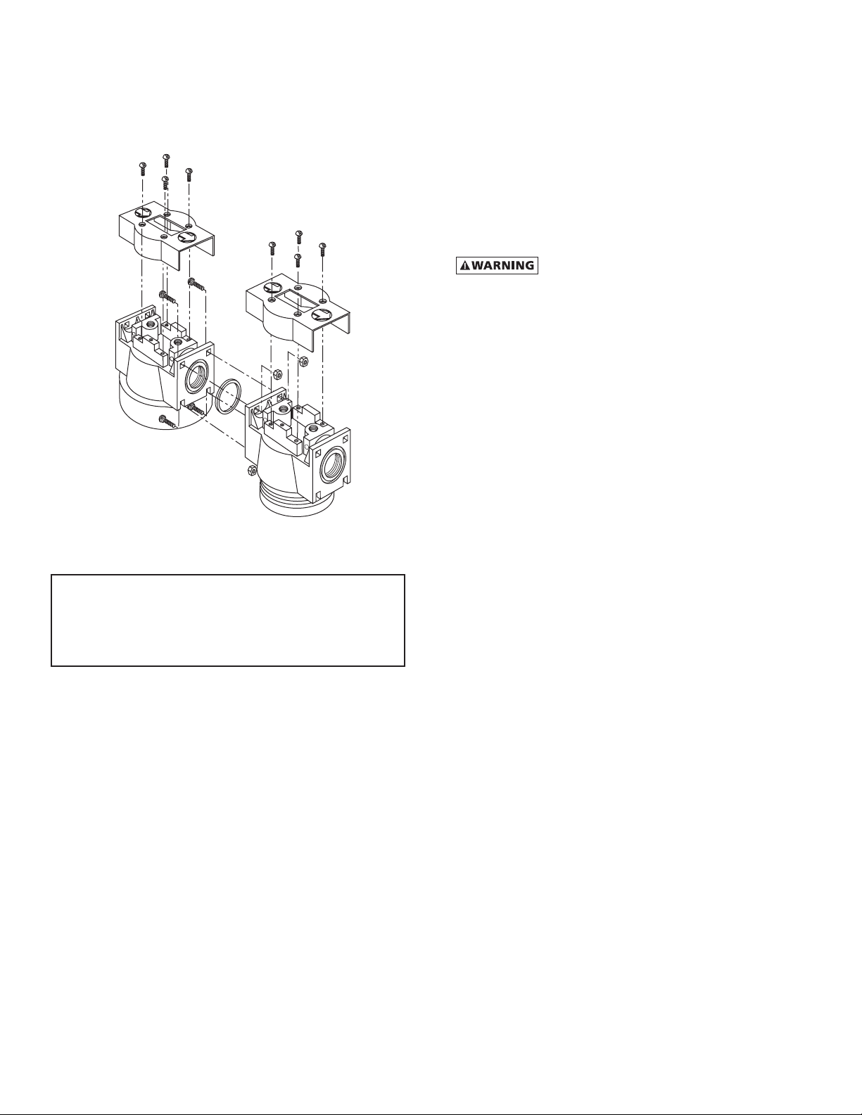
b. Threadedheads
Usefourcarriagebolts,nutsando-ring(soldas
kit).Removeblackplastictopcaps,applygen-
erousamountoflubricanttoo-ring,installo-ring
ingroove,andinstallboltsandnuts.
NOTE: Make certain ow direction through lters is
correct(observepinholeusedforaligningtopcaps).
Grades11,9,7,5,3,1 -when holeis onside closestto
you,inletistoleft.Grade6-whenholeisontheside
fartherfromyou,inletistoleft.
NOTE:Lubricateo-ringwithgenerousamountoflubri-
cantbeforeinstallation.
6. Isolationvalvesandby-passpiping-Foreaseof
service,isolationandby-passvalvesaredesirable.
Incriticalapplications,twoltersinstalledinparallel
maybenecessarytoavoidinterruptionofairsup-
ply.
Figure 1.4
D. Drain provisions
1. InternalAutomaticDrains-Drainline
Thebottomofinternalautomaticdrainsarepro-
videdwith1/8"(insidethreads)forconnectionof
adrainlineifdesired.
2. ExternalAutoDrains-Externalautodrainsmaybe
addedasfollows:
Models12through28-removeinternaldrainand
installadapter(availablefromfactory).Adapter
outletconnectionis1/8"(insidethreads).
Dischargeisatsystempressure;
anchordrainline.
Models32through48-removeadaptertting
frombottomofbowl;1/2"(insidethreads)portis
availableforexternaldrainconnection.
5
2.0 Operation
Donotoperatelteratpressuresin
excessofMaximumWorkingPressureindicatedon
SerialNumberTag.
NOTE:MaximumOperatingTemperature-150°F,66°C.
Liquidltrationabove120°F,49°Cisnotrecommended
sincethereistypicallyoilpresentinavaporstatewhich
passesthroughthelterandcondensesdownstream.
NOTE:Grade1-Ifoperatedabove100°F,38°Cmay
experiencelessthan1000hoursoflifebecauseof
greateroilvaporcontent.
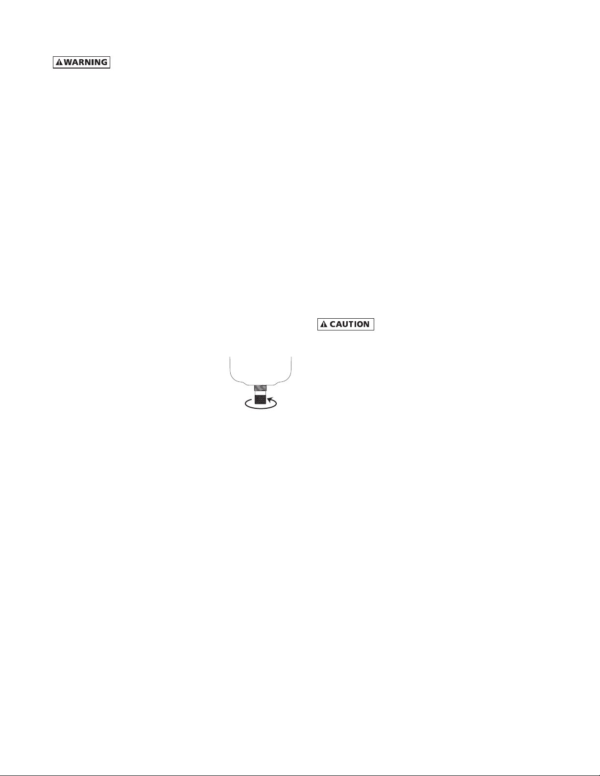
A. Liquid Draining - Grades 11, 9, 7, 5, 3
NOTE:Collectedliquidsmustberemovedtoensure
properoperation.
NOTE:Depressurizeslowly,toavoidlterelement
damage.
1. ManualDrain-Turntoyourright(clockwise)to
openandtoyourleft(counterclockwise)toclose.
2. AutomaticDrain-Liquidswillautomaticallydis-
chargewhensufcientaccumulationoccurs.
a. InternallyMountedAutoDrains-Thesedrains
maybemanuallydrainedbyturningtoyour
right(clockwise)toopenand
toyourleft(counterclockwise)
toclose.
NOTE:Manuallydraininternalauto
drainsdailytoverifydrainfunction.
B. Operational Checkpoints
All Grades
Checkow,pressure,andtemperaturetomakecertain
lterisbeingoperatedwithindesignconditions.
Grades 11,9,7,6,5,3
Checkpressuredropacrossthelter
1. Pressuredifferentialinexcessof6psi(0.42kgf/cm2)
-pressureindicatorinyellowarea-indicatesthatthe
ltersleeveorelementshouldbereplaced.Refer-
encepage7,Figure3.3forgaugescaledetail.
NOTE:Elementshouldbechangedannuallyorwhen
indicatorchangestoyellow,whicheveroccursrst.
NOTE:Pressuredropshouldneverexceed50psi
(3.5kgf/cm2).
2. Checkforsuddenreductioninpressuredrop.This
mightindicate:
a. Possibleleakacrosselemento-ringseal
b. Leakthroughtheelementduetophysicaldamage
OPEN ( TO RIGHT )
Grades 11,9,7,5,3
1. Checktoseethatlterisinstalledleveltoinsure
properdrainage.
2. Checkthatmanualdrainsaredrainedperiodicallyor
thatautomaticdrainsarefunctioning.
3. OnmodelswithLiquidLevelSightglass-Checkthat
liquidlevelisbelowtopofSightglass.
Grade 1
1. Checkforanoilysmellbyopeningthemanualvalve.
Ifanoilysmellexists,thefollowingshouldbe
checked:
a. Filterelementadsorptioncapacityexhausted
b. Leakacrosselemento-ringseal
c. Leakthroughelementduetophysicaldamage
d. Presenceofliquidsbecauseoflackoforfailureof
prelters
e. Flow,pressureandtemperaturesoutsidedesign
conditions
f. Presenceofgaseousimpuritieswhichcannotbe
adsorbed
Methane,carbonmonoxide,carbondioxide
andvariousinorganicgasescannotberemovedbyan
activatedcarbonlter.

6
3.0 Maintenance
A. When to Replace Filter Element
NOTE:Grades7,6,5,3,1-completeelementisreplaced;
Grade9-unlessseparatorcoreisdamagedoutersleeve
onlyisreplaced.
1. Grade6(drydesiccantafterlter)
Initialdrop:1psi(0.07kgf/cm
2
).Pressuredrop
increasesaselementloadswithsolidparticles.
Replacewhenpressuredropreaches6psi
(0.42kgf/cm
2
)(indicatorinyellowarea)orannually,
whicheveroccursrst.Referencepage7,Figure3.3
forgaugescaledetail.
2. Grade11(mechanicalseparator)
Elementshouldnotrequirereplacementunlessphysi-
callydamaged.Ifsludgeaccumulates,elementcanbe
removedandcleanedwithsoapandwater.
3. Grades9,7,5,3
a. Initial(dry)pressuredrop:1psi(0.07kgf/cm
2
)to
2psi(0.14kgf/cm
2
)
b. Operatingpressuredrop:Aslterbecomesliquid
loaded(wetted),pressuredropwillincreaseto2to
6psi(0.14to0.42kgf/cm
2
).Furtherpressuredrop
occursaselementloadswithsolidparticles.
c. FORMAXIMUMFILTRATIONEFFICIENCY,REPLACE
ELEMENTWHENPRESSUREDROPREACHES6PSI
(0.42KGF/CM
2
)(INDICATORINYELLOWAREA)OR
ANNUALLY,WHICHEVEROCCURSFIRST.Reference
page7,Figure3.3forgaugescaledetail.
NOTE:Pressuredropmaytemporarilyincreasewhenow
isresumedafterowstoppage.Pressuredropshould
returntonormalwithinonehour.
NOTE:Grades5and3-Duringnormaloperationbottom
offoamsleevewillhaveabandofoil.Spottingabovethe
bandindicatesthatliquidsareaccumulatingfasterthan
theycanbedrainedandthatpreltrationisrequired.
4. Grade1(activatedcarbonlters)
a. Adsorptioncapacity-1000hoursatratedcapacity.
Elementlifeisexhaustedwhenodorcanbe
detecteddownstreamofthelter.
B. Procedure for Element Replacement
THISFILTERISAPRESSURECONTAINING
DEVICE.DEPRESSURIZEBEFORESERVICING.Iflterhasnot
beendepressurizedbeforedisassembly,anaudiblealarm
willsoundwhenthebowlbeginstoberemovedfromthe
head.Ifthisoccurs,stopdisassembly,isolateand
completelydepressurizelterbeforeproceeding.
1. Isolatelter(closeinletandoutletvalvesifinstalled)or
shutoffairsupply.
2. Depressurizelterbyslowlyopeningmanualdrain
valve.
C. Flow Capacity
Maximumairowforthevariousltersat100psig
(7kgf/cm
2
)isindicatedinTable1.Todeterminemaximum
airowsatinletpressuresotherthan100psig(7kgf/cm
2
),
multiplyowfromTable1byairowcorrectionfactor
fromTable2thatcorrespondstotheminimumoperating
pressureattheinletofthelter.
NOTE:Filtersshouldnotbeselectedbypipesize.Select
usingowrateandoperatingpressureonly.
Table 1 - Maximum Flow @100 psig [
7 kgf/cm2
]
Housing scfm [m3/hr]
12 20 [35]
16 35 [60]
20 60 [105]
24 100 [170]
28 170 [290]
32 250 [425]
36 375 [640]
40 485 [825]
44 625 [1060]
48 780 [1325]
Table 2 - Air Flow Correction Factor
Maximum
Inlet
Pressure
psig 20 30 40 60 80 100 120 150 200 250 300
kgf/cm
2
1.4 2.1 2.8 4.2 5.6 7.0 8.4 10.6 14.1 17.6 21.1
Correction Factor 0.30 0.39 0.48 0.65 0.82 1.00 1.17 1.43 1.87 2.31 2.74

7
3. Removebowl
a. Formodels12through28-bayonetmount-
pushbowlup,turnbowl1/8thturntoyourleft,
andpullbowlstraightdown
b. Formodels32through48-threadedbowls-
unscrewbowlfromheadusinghand,strapwrench
orCspanner.
4. Cleanlterbowl
5. Replaceelement
a. Replacingcompleteelement
1)Pulloffoldelementanddiscard.
2)Makecertaino-ringinsidetopofreplacement
elementisinplaceandpushelementontolter
head.ForHousingsizes40to48,placeelement
inbowlandsecurewithcenteringdevice.
NOTE:Grades5,3,and1-Donothandleelementsby
outsidefoamcover.Handlebybottomendcaponly.
b. Grade9-replacingsleeveonly
1) Pullelementstraightdowntoremove.
2) Removeboltandbottomcapandremovedis-
posableltersleeve.
3) Cleanseparatorcorewithsoapandwaterif
necessary.
4) Slidenewltersleeveoverseparatorcoreand
replacebottomcapandhandtightenbolt.
5) Makecertaino-ringinsidetopofelementisin
placeandpushelementontolterhead.
6. Aftermakingcertainthato-ringinsidetopofbowl
(andonbayonetmountheads,wavespring)arein
place,reassemblebowltohead.
NOTE:Makecertaino-ringisgenerouslylubricated.
NOTE:Wavespringendsshouldbepointeddowntopre-
ventthewavespringfrominterferingwithreassembly.
NOTE:Threadedbowltoheadconnection,generously
lubricatethreadswithahighgrade/temperaturelubricant
goodfor150°F,66°C.
C. Auto Drain Mechanism
Itisrecommendedthatdrainmechanismbereplaced
annually.
Separator Core
Replacement Sleeve
Bottom Cap
Bolt
Bowl o-ring
Element O-ring
Element
Bowl o-ring
Element O-ring
Grade 9 - Sleeve Replacement All Grades - Element Replacement
Wave Spring
Models 12-28
Figure3.1

8
Dimensions and Weights
Filter Type HF(Grade)- 12 16 20 24 28 32 36 40 44 48
Replacement Element E(Grade)- 12 or 12S 16 or 16S 20 or 20S 24 or 24S 28 or 28S 32 or 32S 36 or 36S 40 or 40S 44 or 44S 48 or 48S
Nominal Air Flow
scfm @100 psig (m
3
/hr @ 7.0 bar) 20 (35) 35 (60) 60 (105) 100 (170) 170 (290) 250 (425) 375 (640) 485 (825) 625 (1060) 780 (1325)
In/Out Connection NPT or BSP 3/8, 1/2 3/8, 1/2 3/8, 1/2 3/4, 1 3/4, 1 1, 1-1/4, 1-1/2 1, 1-1/4, 1-1/2 2, 2-1/2 2-1/2 2-1/2
"A" in. (mm) 4.13 (105) 4.13 (105) 4.13 (105) 5.25 (133) 5.25 (133) 6.44 (164) 6.44 (164) 7.63 (194) 7.63 (194) 7.63 (194)
"B" in. (mm) 8.15 (207) 10.05 (255) 12.40 (316) 13.32 (338) 17.57 (446) 20.80 (528) 25.29 (642) 29.08 (739) 34.83 (885) 40.96 (1040)
"C" in. (mm) 6.40 (163) 8.59 (224) 10.97 (285) 11.74 (298) 15.99 (406) 18.98 (482) 23.47 (596) 26.83 (681) 32.58 (827) 38.71 (983)
"D" in. (mm) 3.00 (76) 3.00 (76) 3.00 (76) 3.50 (89) 3.50 (89) 4.00 (102) 4.00 (102) 4.00 (102) 4.00 (102) 4.00 (102)
Weight lb. (kg) 4.14 (1.88) 4.5 (2.04) 4.7 (2.13) 6.3 (2.9) 6.9 (3.1) 10.2 (4.63) 11.3 (5.13) 28 (12.70) 33 (14.97) 38 (17.24)
Maximum Working Pressure Housing - 300 psig, 21.1 kgf/cm
2
Models with Internal Drain or
Liquid level indicator - 250 psig, 17.6 kgf/cm
2
Housing - 300 psig, 21.1 kgf/cm
2
Models with Internal Drain or
Liquid level indicator - 250 psig, 17.6 kgf/cm
2
Maximum Operating Temperature 150°F, 66°C 150°F, 66°C
Head Material Aluminum Aluminum
Bowl Material Aluminum Aluminum
Liquid Level Indicator Material Isoplast Isoplast —
NOTE:DimensionsandWeightsareforreferenceonly.Requestcertieddrawingsforconstructionpurposes.
OUTLET
CLEARANCE
FOR SERVICING
CLEARANCE
FOR SERVICING
INLET OUTLET
INLET
"A"
"C" "B"
"D"
1" (26mm)
"A"
"C"
"B"
"D"
2.3" (58.4mm)
OUTLETINLET
INLET OUTLET
CLEARANCE
FOR SERVICING
"A"
"C" "B"
"D"
2.3" (58.4mm)
CLEARANCE
FOR SERVICING
"A"
"C"
"B"
"D"
2.3" (58.4mm)
HEX WRENCH
3.00 ACROSS FLATS
Sizes HF(Grade) 12, 16, 20 Sizes HF(Grade) 24, 28 Sizes HF(Grade) 32, 36 Sizes HF(Grade) 40, 44, 48
Figure3.3
DifferentialPressure
Gauge
Figure3.2

9
SERVICE DEPARTMENT: (724) 746-1100
WARRANTY
Themanufacturerwarrantstheproductmanufacturedbyit,whenproperlyinstalled,operated,applied,andmain-
tainedinaccordancewithproceduresandrecommendationsoutlinedinmanufacturer’sinstructionmanuals,tobe
freefromdefectsinmaterialandworkmanshipforaperiodofone(1)yearfromdateshipmenttothebuyerbythe
manufacturerormanufacturer’sauthorizeddistributorprovidedsuchdefectisdiscoveredandbroughttothemanu-
facturer’sattentionwithintheaforesaidwarrantyperiod.
Themanufacturerwillrepairorreplaceanyproductorpartdeterminedtobedefectivebythemanufacturerwithin
thewarrantyperiod,providedsuchdefectoccurredinnormalserviceandnotasaresultofmisuse,abuse,neglect
oraccident.Normalmaintenanceitemsrequiringroutinereplacementarenotwarranted.Thewarrantycoversparts
andlaborforthewarrantyperiod.Repairorreplacementshallbemadeatthefactoryortheinstallationsite,atthe
soleoptionofthemanufacturer.Anyserviceperformedontheproductbyanyoneotherthanthemanufacturer
mustrstbeauthorizedbythemanufacturer.
Unauthorizedservicevoidsthewarrantyandanyresultingchargeorsubsequentclaimwillnotbepaid.
Productsrepairedorreplacedunderwarrantyshallbewarrantedfortheunexpiredportionofthewarrantyapplying
totheoriginalproduct.
Theforegoingistheexclusiveremedyofanybuyerofthemanufacturer’sproduct.Themaximumdamagesliabilityof
themanufactureristheoriginalpurchasepriceoftheproductorpart.
THEFOREGOINGWARRANTYISEXCLUSIVEANDINLIEUOFALLOTHERWARRANTIES,WHETHERWRITTEN,ORAL,ORSTATU-
TORY,ANDISEXPRESSEDINLIEUOFTHEIMPLIEDWARRANTYOFMERCHANTABILITYANDTHEIMPLIEDWARRANTYOF
FITNESSFORAPARTICULARPURPOSE.THEMANUFACTURERSHALLNOTBELIABLEFORLOSSORDAMAGEBYREASONOF
STRICTLIABILITYINTORTORITSNEGLIGENCEINWHATEVERMANNERINCLUDINGDESIGN,MANUFACTUREORINSPECTION
OFTHEEQUIPMENTORITSFAILURETODISCOVER,REPORT,REPAIR,ORMODIFYLATENTDEFECTSINHERENTTHEREIN.
THEMANUFACTURER,HISREPRESENTATIVEORDISTRIBUTORSHALLNOTBELIABLEFORLOSSOFUSEOFTHEPRODUCTOR
OTHERINCIDENTALORCONSEQUENTIALCOSTS,EXPENSES,ORDAMAGESINCURREDBYTHEBUYER,WHETHERARISING
FROMBREACHOFWARRANTY,NEGLIGENCEORSTRICTLIABILITYINTORT.
Themanufacturerdoesnotwarrantanyproduct,part,material,component,oraccessorymanufacturedbyothers
andsoldorsuppliedinconnectionwiththesaleofmanufacturer’sproducts.
AUTHORIZATION FROM THE SERVICE DEPARTMENT IS NECESSARY BEFORE MATERIAL
IS RETURNED TO THE FACTORY OR IN-WARRANTY REPAIRS ARE MADE.

HF SERIES
Compressed Air Filters
Models HF(grade)-12 through HF(grade)-48
SPX FLOW, INC.
4647 S.W. 40th Avenue
Ocala, Florida 34474-5788 U.S.A.
P: (724) 745-1555
F: (724) 745-6040
E: hankison.americas@spxflow.com
www.spxflow.com/hankison
Improvements and research are continuous at SPX FLOW, Inc.
Specifications may change without notice.
ISSUED 10/2015 Form No.: 4011203 Revision: D
COPYRIGHT ©2015 SPX FLOW, Inc.
This manual suits for next models
10
Table of contents
Other SPX FLOW Water Filtration System manuals


