Hornady Lock-N-Load 366 Auto User manual

Lock-N-Load®366 Auto™
Automatic Shotshell Reloader
OPERATION MANUAL

2
TABLE OF CONTENTS
Steps: Page
Overview .......................................3
Standard Loads and Bushings.....................3
Setting up your 366 Auto .........................4
Function and Adjustment .........................5
1. Resize and De-Prime (Station 1A) .........6
2. De-Prime Only (Station 1).................7
3. Prime (Station 2).........................8
4. Powder Drop (Station 3) ..................9
5. Wad Seating (Station 4) .................10
6. Shot Drop (Station 5) ....................11
7. Crimp Starter (Station 6) ................12
8. Crimp (Station 7)........................13
9. Crimp Taper (Station 8) ..................14
Adjustment of Auto Advance.....................15
Trouble Shooting ...............................16
Converting to Another Gauge ....................18
List of Illustrations: Page
1. Function and Adjustment .....................5
2. Resize and De-Prime. ........................6
3. De-Prime ...................................7
4. Prime.......................................8
5. Powder Drop ................................9
6. Wad Seating ...............................10
7. Shot Drop ..................................11
8. Crimp Start ................................12
9. Crimp......................................13
10. Taper Crimp ................................14
11. Adjustment of Auto Advance.................15
12. Exploded View. .............................20
List of Charts: Page
Powder Bushings ...............................19
Bill of Materials ................................21

3
SHOTSHELL RELOADER INSTRUCTIONS
To help you load completely satisfactory ammunition the
first time you operate your 366 Auto, these instructions have
detailed steps of operation and adjustment to help in avoiding
problems.
To begin loading shot shells, you will need powder, shot,
primers and wads and empty hulls. Before purchasing any of
these components, first note what charge the standard bushing
furnished with your loader will throw by weighing your charge.
Listed on the label on the outside of the carton is a powder
bushing and shot bushing number which is referenced to a
powder weight and brand, as well as shot amount and type.
STANDARD LOADS AND BUSHINGS
If the referenced powder is not available, refer to the
recommended load chart on page 19. This chart will show the
other powder weights and brands it will dispense. It is not to
be taken for a reloading manual. Loading data from the major
powder manufactures is furnished, when available, to help you
in getting started. Unless you have experience in shot shell
reloading, ask your dealer to help you pick the best starting
combination, or contact Hornady’s Reloading Advisory Center.
IMPORTANT: Never mix powders or use unidentified powder.
Do not use smokeless powder in old firearms until the firearm
is certified safe. Do not exceed recommended loads.
Your 366 Auto is a precision machine. It is the only loader to
feature full-length resizing with each stroke, automatic primer
feed, swing-out wad guide, three stage crimping with taper-
loc for factory tapered crimp, automatic advance to the next
station and automatic ejection with the option of a gas assisted
automatic advance.
This press should give you many years of enjoyable, trouble-
free service. Any problems that you have can generally be
corrected by slight adjustments of the dies and punches in each
station. If you are unable to correct the problem, please write
us or call:
Hornady Mfg. Co.
PO Box 1848
Grand Island, NE 68802-1848
800-338-3220
DO NOT RETURN THE LOADER TO YOUR DEALER.

4
SETTING UP YOUR 366 AUTO
Mount your 366 Auto securely toward the front of a sturdy
bench. All operations of the press are to a full stop, so the
operating handle must clear the bench when in the down
position. Since the shells are ejected down a chute, out the
back of the loader, you may want to set your loader up on riser
blocks (010060) to provide access to the completed shells. An
alternate method to catch finished shells would be to cut a hole
in the bench and place a box underneath.
1. Before filling the shot and powder hoppers, turn the
measure assembly upside down and carefully push the
charge bar out and check the powder and shot bushing
numbers.
2. Your loader was furnished with standard bushings,
12 GA. 11⁄8oz. #7 ½ shot, 468 Powder Bushing; 20 GA.
7⁄8oz. #9 shot, 393 Powder Bushing; 28 GA. ¾ oz.
#9 shot, 303 Powder Bushing; 410 GA. ½ oz. #9 shot,
291 Powder Bushing but double check to insure you
will dispense the correct weight of powder and shot.
3. While the charge bar is removed or pushed back,
check that the measure casting seals (rubber washers)
are in the recess in the measure casting.
4. Reinstall the bushings and push the charge bar back
in place. If the powder slide should drop out of the
measure assembly, do not disassemble the measure
plate.
5. Replace the powder slide by pressing it in from the side
against the detent spring, pull spring back and fit into
slot.
6. Reinstall the measure assembly by tilting the casting
as you slip the measure plate and shot rotor spring
under the hold down washer, and the charge bar into
the slot of the charge bar cam.
7. Secure assembly in position with measure attaching
bolt.
8. Install the primer tube in the die head casting and fill
the primer tray according to instructions furnished
with it. Do not fill the tube at this time.
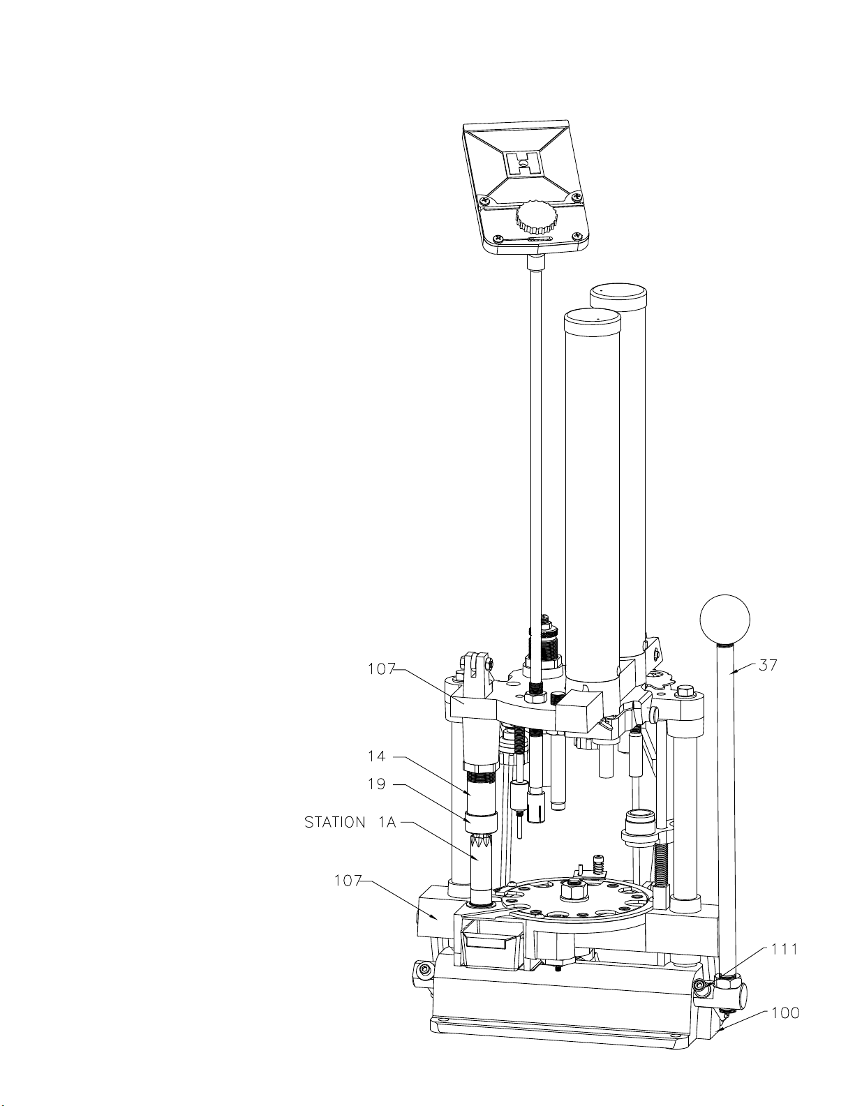
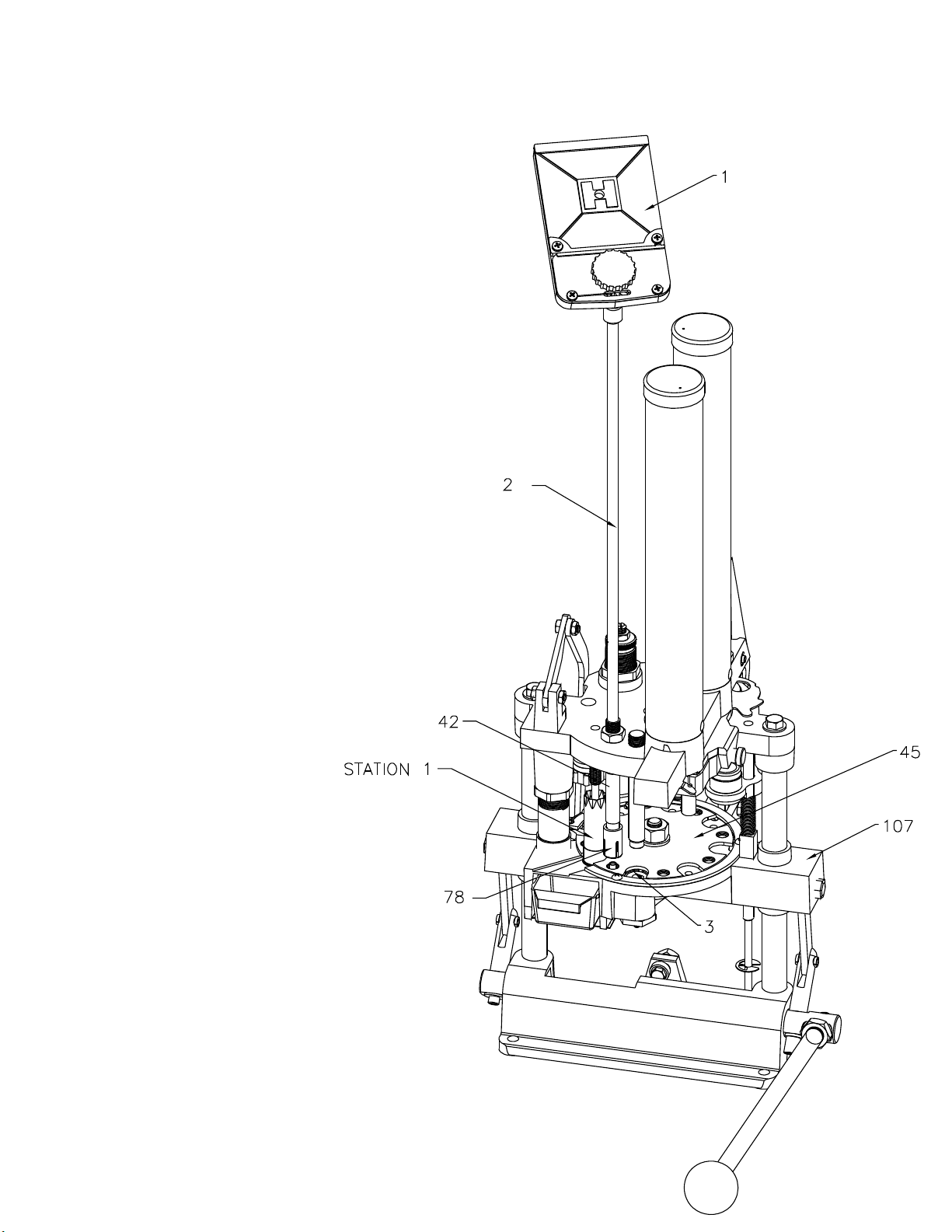
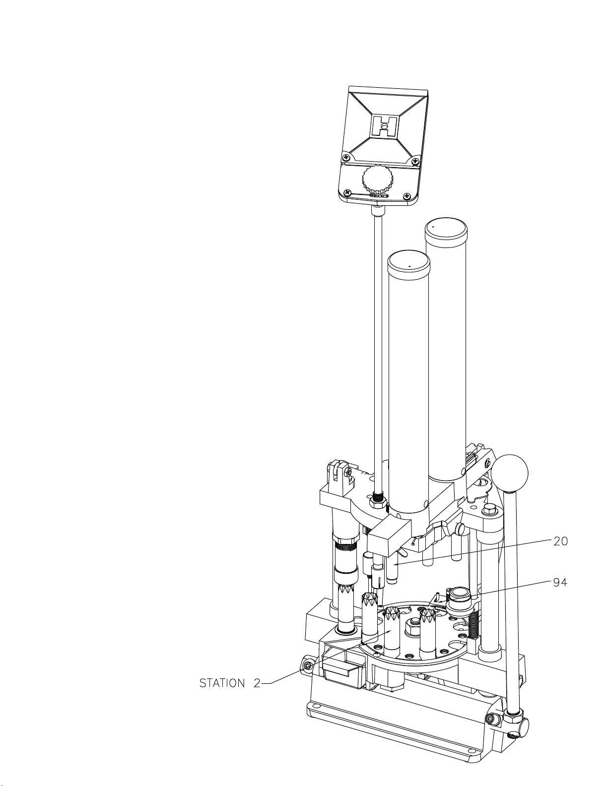
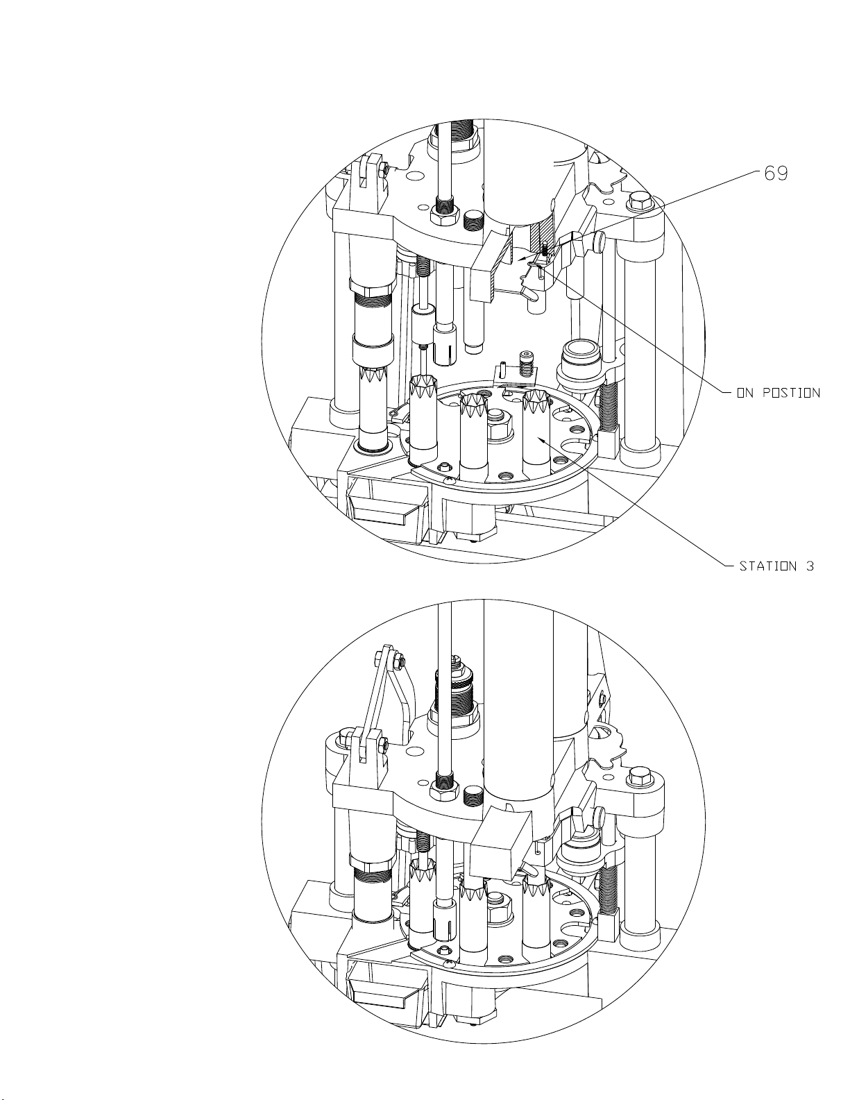
9. Check the individual stations of the loader for
alignment to make sure nothing has loosened during
shipping. Shut off the powder slide (push in) and the
shot rotor (pull forward) while checking each station.
READ THIS SECTION BEFORE ATTEMPTING TO LOAD AMMUNITION!

5
FUNCTION AND ADJUSTMENT
The following is a detailed description of the operation and
adjustment of the 366 Auto Reloading Press. This press has
been pre-adjusted at the factory for Remington STS cases, but
every person has a preference about how the finished product
should look, so some changes might be necessary. The reloader
should begin by advancing a single shell through each station
to familiarize himself with the operation and adjustment of
each position. The illustrated discussion which follows shows
the 366 with all eight stations filled. Since your first shell will be
the only one in the loader, be sure the shot and powder slides
are off at the beginning of the sequence.
Sort your shot shells by brand and type. Refer to the loading
manuals provided for recommended loads for your shot shells.
Fig. 1: Function and Adjustment

6
STEP 1: STATION 1A (RESIZE AND DEPRIME)
Place an empty shell in Station 1A, making sure the deprime
punch enters the case mouth and the shell is reasonably
centered under the size die (14). Pull the operating handle (37) to
the bottom of the stroke. Make sure nothing interferes with the
handle reaching bottom. When the operating handle is pulled,
the platen casting (107) rises until the eccentric arm stop (111)
contacts the base casting (100). At this point, the shell should
be completely enclosed in the size die (14) and there should be
no gap between the size die ring cap (19) and the platen casting
(107). When the handle (37) is returned, the de-prime punch
guide (8) pushes the case from the die. The expander (8) is
threaded on the deprime bolt (62) which is forced down by the
clevis link (13) attached to the head casting (7). The size die (14)
should size the brass head and rim to permit the chambering
of that shell in any firearm. Properly adjusted, the size die (14)
just contacts the platen casting (107). All other dies are set
from this adjustment point, but are designed with all stations
full. Interference with the handle (37) can cause light powder
charges or primers not seated properly. The size die (14) and the
size die ring cap (19) must be kept tight at all times.
Fig. 2: Resize and De-Prime

7
STEP 2: STATION ONE (DE-PRIME ONLY)
Insert the case in station.
1. Normally, at this time, we would fill the primer tube (2), but
since we are working with a single shell, drop only one primer
from the tray (1) into the primer tube (2). Now pull the handle
(37). As the handle (37) makes a complete cycle, the shell
will automatically advance to the next station also dropping
the primer into the hole in the primer seat pad (3). Some
individuals may wish to bypass Station 1A but a shell must be
in place in Station 1 before pulling the handle (37). The shell
automatically advances on the return stroke and if Station 1
is empty, there will be a gap in the reloading sequence.
Primer Drop: Until you are more familiar with your reloader,
always return the handle smoothly and, at first slowly. The
primer is dropped when the shell plate (45) contacts the plastic
primer drop stop unit (78) at the bottom of the down stroke,
and spreads the fingers of this unit, allowing the primer to slip
into the hole provided in the shell plate (45). At this point, make
sure that the metal portion of the primer feed body (42) does not
make contact with the shell plate. Such contact will turn a burr
on the inside and prevent primers from falling.
The primer seat pad (3) is notched to improve the primer drop,
but the primer only falls at the speed of gravity, so the handle
(37) must not be raised too rapidly, or the primer could be
jammed between the shell plate (45) and the platen casting
(107). Therefore, operate the handle smoothly, and only as fast
as primers will reliably drop into the primer seater pad (3).
Fig. 3: De-Prime

8
STEP 3: STATION TWO (PRIME)
Pull the handle (37) through a complete stroke. The primer
seating punch (20) or the optional spring loaded primer seater
punch (010051) will enter the case and push the case down,
over the primer in the primer seating pad (3). On the return
stroke, the primer seating pad (3) will push the case back up
into position and the shell plate (45) will advance to the next
position. Before continuing the loading sequence, remove the
primed case, to inspect the primer seat depth. To remove, lift
the pawl (94) from the indexing position and rotate the shell
plate (45) back to station one and inspect the seated primer.
The primer should be flush with the case head. If the primer is
not fully seated, the primer seater punch (20) must be adjusted.
Different brands of cases have different base wad heights.
Replace the case in position at Station Two. Loosen the primer
punch lock nut (23). Pull the handle (37) down, and steadily
lower the primer seater punch until you feel the punch start
to interfere with the handle (37). The primer seating punch
(20) should then be backed up just enough to eliminate any
interference. Your loader was factory set to load the low base
wad of the modern compression formed type cases and may not
need any adjustment. The primer seater pad notch should be on
your right as you face the loader.
Fig. 4: Prime

9
STEP 4: STATION THREE (DROP POWDER)
Before pulling the handle (37), pull the powder slide (69) toward
you. The spring (71) will lock the slide in place in the
second slot of powder slide (69). The powder drop is
now on. During the stroke, the powder bushing
will advance to the Powder Drop station.
Normally, we would leave the powder
slide on, but since we are taking one
shell through each step, push the
powder slide back and shut off the
powder. (Do this before pulling the
handle again.)
There is no adjustment to the
powder drop, but the drop tube
should be kept clean and dry and
must be able to float freely in the
head casting. To clean the drop
tube, use brake cleaner to remove
all oils.
Fig. 5: Powder Drop

10
STEP 5: STATION FOUR (WAD SEATING)
Insert a wad in the wad guide (106A). Pull the operating handle
(37) through a complete stroke. When the handle (37) is
pulled, the spring (106B) around the wad guide rod (105)
turns the wad guide bracket (101) to align the wad with
the case. The unit then rises until the wad is stopped
with the platen casting (107) by the wad ram (48).
The case continues upward until the spring fingers
(77) have entered the case mouth, and then
pushes the wad guide (101) upward until the wad
is seated in the case. The spring fingers (77)
have enough resistance to prevent the wad
from going through until the spring fingers (77)
are in the case. At the completion of the return
stroke, the wad guide bracket (101) will swing
forward for the next wad to be inserted. The
wad guide bracket should have 1/8" clearance
above the shells. The empty shells vary in length
so a closer setting would not be beneficial. Be sure
the wad seating ram (48) is set high enough for the
wad to swing into position with out being folded by
early contact with the wad seating ram (48).
Wad pressure is adjusted by raising or lowering
the wad seating ram (48). Most one-piece
plastic wads today will self-adjust when the
shell is crimped. Generally, the wad should
be seated to allow 5/8" clearance between
the case mouth and the shot.
Fig. 6: Wad Seating

11
STEP 6: STATION FIVE (SHOT DROP)
Before pulling the handle (37), rotate the shot shut-off (70)
backward, turning on the shot. Now, lower the handle (37). The
shot drop tube (47) enters the case mouth and then both case
and shot drop tube (47) rise together to the top of the stroke. In
this fashion, all the shot enters the case without being spilled.
No adjustment of this station is possible. Upon completion of
the stroke, the shells will advance to the next station. Normally,
we would leave the shot drop on, but since we are taking a
single shell through the sequence, rotate the shot rotor (70)
forward to shut off the shot.
Fig. 7: Shot Drop

12
STEP 7: STATION SIX (CRIMP START)
As you lower the handle (37), the shell at Station Six enters the
crimp starter (82). The plastic body has ridges on the inside
to align with the old crimp and restart the folds. The outside
of each crimp starter (82) has a ridge corresponding with the
inside, so if manual alignment is necessary with damaged
crimps, follow these ridges. A hole in the case mouth of ¼"
should be left when the shell completes this station. Hornady
loaders come with eight point crimp starter installed, but if
you are using another crimp, substitute with either smooth for
paper or six point plastic, included with your loader. The plastic
starter unit unthreads from the rod (65) extending through the
main body. The amount of “start” may be adjusted, but too
much can cause the wall of the case to collapse, producing a
defective shell.
Fig. 8: Crimp Start

13
STEP 8: STATION SEVEN (CRIMP)
Fig. 9: Crimp
As you pull the handle (37), the shell in Station Seven will enter
the crimp die (59). The shell will contact the inside of the die
and raise the die body (59) as it goes up. It will then contact the
crimp plunger (58) and the crimp will be closed. On the return
stroke, the shell will be pulled from the crimp plunger (58)
but the crimp die (59) will keep pressure on the case to retain
the proper shape. Since different manufactures’ cases have
varying types of construction, different settings are required
for best results. The two-stage die enables the user to create
a reloaded round that has approximately the same tapered
mouth as a factory shell. There are two adjustments to the
crimp die assembly (57, #58, and #59); the larger outer position
adjusts the die body (59), the threaded bolt through the center
of the die adjusts the crimp plunger (58). To adjust the die, refer
to the number of threads exposed above the large die body
locking nut (15) as reference points for each brand of case.
For Winchester AA type shells, ten to ten and one half threads
should remain above the locking ring (15); for Remington Blue
Magic and Federal Gold Metal Cases, eleven to thirteen threads
should be exposed. These measurements are approximate and
may need adjustment up or down, depending on the plastic and
components, but should be correct in most situations. Before
adjusting the crimp the crimp die (59), the crimp plunger (58)
should be raised a few turns by loosening lock nut (15) and
turning the crimp die bushing (57) clock wise. Then, make the
necessary die body (59) adjustments, and follow by crimping
the case. At this point, the case mouth will not be closed. Lower
the crimp plunger (58) in small increments, each time recrimping
the shell until the final desired crimp depth is obtained. The
crimp depth is up to you, but excessive depth shortens case life,
while a crimp that is too shallow will not yield uniform velocity
or good patterns. A good practice is to keep a factory round on
hand for reference

14
STEP 9: STATION EIGHT (TAPER CRIMP)
Fig. 10: Taper Crimp
The taper crimp is a smooth crimp starter (82) and will taper the
finished case better than factory loads. As the shell at Station
Eight enters the taper crimp die (59), the mouth of the shell will
be “rolled.” On the return stroke, the shells advance, but the
shell in Station Eight contacts a cam in the platen casting (107),
moves to the left, and drops through a hole in the platen casting
(107) down the chute (108) to the back.
Adjustment of the taper crimp (82) is done by loosening the lock
nut (29) and raising or lowering the taper crimp starter (82) to
obtain the desired taper on the case mouth.
At this point in a normal reloading sequence, you would have
a completed shell at each station. To begin reloading, go
back to the beginning and follow instructions for Step 1 and
Step 2, but this time fill the primer tube (2) when you insert a
shell in Station One. As the shells advance around the loader,
remember to turn on the powder and shot when the shells
advance to the positions, and to reinsert a shell at Station One
and a wad in the wad guide after each pull of the handle. You
can continue the sequence until all your empty shells have
been reloaded but always remember to check the powder and
shot hoppers (80) and make sure a primer drops on each stroke.
If you refill the primers, shot and powder after each 100 rounds,
you will never load shells without components.

15
ADJUSTMENT OF AUTO ADVANCE
When the operating handle (37) is pulled all the way up, a
spring (98) swings the pivot arm (85) and the advance pawl (94)
to your right. The hook of the pawl rides in the gap between
the shell plate (45) and the shell plate ring (110). On the return
stroke, the roller on the base casting (100) contacts the curve
on the pivot arm (85) and the entire unit is cammed toward the
left, advancing the shells to the next position. The cam bearing
(12) is mounted off-center on the bolt (25) so when it is turned,
the cam bearing is shifted right or left. If an adjustment is
necessary, loosen the lock nut (28) and turn the eccentric bolt
(93) with a screwdriver. It is necessary to hold the eccentric
bolt (93) with the screwdriver when tightening the nut (28).
Fig. 11: Adjustment of Auto Advance

16
TROUBLESHOOTING
Handle will not come
to bottom of stroke
Do not force the handle
(37). If you meet with
any resistance, shut off
the shot and powder
and slowly return the
handle (37) back to
normal while unlatching
the rotating pawl (94).
1. Check to see the loader is mounted near the front of the bench,
allowing the handle (37) to come completely down.
2. Check to see if the size die body (14) adjustment has changed
or if the size die ring cap (19) has loosened.
3. Check that the de-prime punch guide (8) is threaded all
the way up on the size die ejector bolt (62).
4. Check to see that you are not seating a second primer on top of an already primed case.
5. Check the primer seater punch (20) to see if it is adjusted too low.
Readjust to seat the primer when the handle (37) is depressed.
6. Check to see that you aren’t trying to seat a second wad on top
of another and the wad entered the shell correctly.
7. Check to see that shells are in alignment and the correct shell is in each station.
8. Check for an obstruction inside the shell which would prevent
you from depriming or repriming the case.
9. Check to see that you aren’t trying to load a high base wad
shell when you are set up for low base wads.
10. Check to see if a loaded shell has rolled underneath one of the eccentric arms.
Handle will not turn
to normal position
on backstroke.
DO NOT FORCE
THE HANDLE. Shut
off the powder and
shot and unlatch the
rotating pawl (94).
1. Check the clevis link (13) to see if it is bent and hanging up on
the size die eject bolt (62). Replace if necessary.
2. Check the primer seater station to see that the primer was fully
seated. If not, lower the primer seater punch (20).
3. Check to see that the wad is being fully seated and not
pulling back up into the wad guide bracket (101).
4. Check the wad guide bracket (101) to see that the wad guide return spring (106B)
is attached and that the bracket is fastened to the wad guide rod (105).
5. Check the charge bar cam (9) adjustment to see that it hasn’t slipped.
6. Check for an obstruction, spilled shot, etc., between the shell plate ring (110)
and the platen casting (107). If there is, you may need to rotate the pawl
(94) clock wise and take the shell plate nut (91) off and lift the shell plate
(45) off the platen (107) and clean out the shot. When the shot is cleaned
out, replace the components in reverse order as you took them off.
7. Lift each shell up against the shell plate (45) to see if a primer flange
may be catching in a platen casting (107) indention.
8. Check to see if the shell plate (45) is dragging on the shell retainer spring (63).
9. Check to make sure the primer was fully removed at Station One.
Primers do not drop
or drop erratically.
If primers do not drop into
the shell plate (45), or drop
erratically, shut off the shot
and powder and unlatch
the rotating pawl (94).
1. Make sure the primer feed body (42) is adjusted low enough to open
the primer stop unit (78) which allows a primer to drop.
2. Check alignment of primer feed body (42) with the shell plate (45). The taper of the primer
feed body (42) should enter the chamfer in the shell plate (45), but not touch. When there
are no shells in the crimp die (59), pressure on the size die (14) may tip the platen casting
(107) enough to cause erratic drop. When possible, make adjustments with all stations full.
3. Check that the auto advance unit (83) is fully advancing and stopping in the correct location.
4. See that the primer feed body (42) is not burred on the inside, preventing
the primers from dropping freely. If burred, remove with small file.
5. Check the primer feed body (42) to see that it is not burred on the ends and that it is straight.
6. Inspect the plastic primer top unit (78) for flash around the fingers
and make sure that the foot moves freely on the body.

17
Wads are not
seating properly,
tearing or tipping.
Shut off the powder
and shot and detach the
rotating pawl (94) and
return the handle (37) to
normal position. DO NOT
force the handle (37) back,
as it may not be able to
move due to the swinging
wad guide (101). You may
have to cut the wad in
half if it cannot be pushed
through into the case.
1. Check your operation of the tool, making sure you allow enough time for the wad
to correctly align with the ram. The wad guide (106) should be set to swing out just
far enough for easy insertion of the wad; swinging too far will delay the bracket.
2. Make sure the wad guide bracket (101) clears the shell by about 1/8" so the
spring fingers (77) enter the case mouth before the wad starts through.
3. Check shell length; variations may cause the case mouth to catch on the
bottom of the wad guide (106); preventing it from aligning correctly.
4. Check the E clip (104), which is about 3" from the bottom of the wad guide rod (105),
to see if it has slipped or broken off the wad guide rod (105); it could allow the wad
to move through the spring fingers (77) before they enter the case mouth.
5. Check the spring fingers (77) to see if they are broken or weak.
6. Check the shells to see that the case mouth is opened up enough to allow the
wad to be seated. Case mouths which are too tight must be flared open, either
by hand or with an expander in the size die (14) or de-prime station (1A).
Crimp is concave or
opens after being
ejected from die.
Crimp not satisfactory
in appearance.
Detach the rotating
pawl, shut off the
powder and shot.
1. If the crimp is concave (sinks):
a. Reduce the wad seating depth to see that the shot comes to about
5/8" from the case mouth in the crimp starter station.
b. Check to see if powder slide is turned on.
c. See if you have correct powder bushing.
d. Make sure the wad length is correct for the case you are loading.
e. Check to see if the shot bushing is correct. Adjust the crimp plunger (58).
2. If the crimp is bulging open:
a. Check to see if you have seated the wad deep enough.
b. Inspect powder bushing to insure correct powder charge used.
c. Check shot bushing for shot size used.
d. Make sure you have the correct wad length for load being used
e. Double-check all components to make sure they are
the correct ones for the specific load.
f. Check adjustment of crimp plunger (58).
3. If the finished shell does not have enough taper in the end or is
flared, lower the taper crimp die (82) (Station Eight).
4. If crimp isn’t deep enough, turn the crimp plunger (58) in the final crimp down.
5. If the shell swirls in the center, the plastic shell has elongated or
stretched. No adjustment is generally possible to remove the swirl.
This is common, and was probably in the factory shell.
6. Check to see that you have the proper crimp starter (82) installed. Eight point for most
plastic target cases, six point for most plastic hunting loads and smooth for paper
cases. If the case buckles at the mouth or wrinkles after final crimp or during the crimp
start, raise the crimp starter. Also check to insure you have the correct components.

18
CONVERTING TO ANOTHER GAUGE
If you purchase a die set for a different gauge, always
remember to start installation by adjusting the full length size
die (14) FIRST! When adjusted properly, the size die should just
contact the platen (107) at the top of the stroke. Then, install
other dies and punches using the size die (14) as a guide.
Stations should be adjusted by actually reloading a shell. The
exception is the primer seating pad (3) to ensure seating the
primer to the full depth of the primer pocket. Adjust the wad ram
(46) to provide best crimp (except as noted in sinking crimps or
bulging).
By showing you how to “fine tune” and troubleshoot the
366 Auto, we hope to save you downtime and maximize your
reloading enjoyment. Your 366 Auto is a fine progressive
reloader…once the first cycle is completed; it kicks out a
finished shell with every stroke.
ABOUT WADS AND WAD PRESSURE: We recommend the use
of 1-piece plastic wads. They are more convenient, and do not
require any specific wad pressure. They need to be seated only
deep enough to obtain a satisfactory crimp.
PLEASE NOTE: Normally, few problems are encountered when
reloading shot shells. However, variations in the powder lot,
different brands of primers and other components can cause
substantial changes in pressure. Hornady Manufacturing
Company has no control over the components and equipment
which may be used with this published information; no
responsibility is implied or assumed for modern firearms and
does not exceed manufacturer’s pressure recommendations.
Further data may be obtained from:
• www.hodgdon.com
• www.imrpowder.com
• www.alliantpowder.com
• www.accuratepowder.com
• www.wwpowder.com
• www.ramshot.com

19
POWDER BUSHING CHART
GRAINS
Accurate Nitro 100
IMR 700-X
IMR PB
IMR SR 7625
IMR 800-X
IMR SR 4756
IMR MR 4227
Alliant American Select
Alliant Red Dot
Alliant Green Dot
Alliant Unique
Alliant Herco
Alliant Blue Dot
Alliant 2400
Alliant 20/28
Alliant E-3
Alliant 410
Hodgdon Clays
Hodgdon International
Hodgdon Universal
Hodgdon HS-6
Hodgdon HS-7
Hodgdon H110
Hodgdon Titewad
Hodgdon Lil’ Gun
Hodgdon LGSH
Hodgdon Titegroup
Scot 1000
Scot Solo 1250
Win. 540
Win. 571
Win. 296
Win. Super Target
Win. Super Lite
Win. Super Field
Win. Super Handicap
10 330 256
11 256 266
12 363 266 318 291 250
13 336 393 327 300 363 330 256 259 363 256
14 366 345 363 390 354 291 333 266 300 266
15 402 372 366 303 423 381 300 345 426 390 354 384 309 324 272 324
16 414 390 390 438 420 381 393 357 438 429 402 366 291 396 318 330 330 336
17 420 429 402 381 402 423 453 435 393 363 450 441 414 300 300 408 330 342 447 300 345 342
18 432 441 414 390 414 432 468 447 414 366 330 369 465 456 423 390 309 309 420 339 351 456 420 309 417 354 354
19 444 453 426 402 423 408 447 480 456 414 426 372 378 477 468 435 402 318 318 432 348 360 468 432 318 318 429 363 363
20 456 465 435 414 429 417 456 489 468 423 438 381 384 483 447 327 330 441 357 369 480 444 327 330 438 372 372
21 468 447 426 438 426 357 468 498 480 435 450 390 390 459 420 336 339 453 366 378 456 336 450 381 381
22 486 456 438 447 435 366 444 462 396 399 471 429 345 348 462 372 387 504 468 345 459 390 390
23 498 465 444 459 447 453 471 408 438 351 357 474 381 396 480 351 471 402 399
24 474 453 468 459 465 414 447 360 363 486 390 405 489 360 363 480 408
25 486 462 480 471 390 474 489 423 507 456 366 369 492 396 498 366
26 474 489 480 534 483 498 435 468 375 378 405 420
27 486 489 408 441 480 381 384 414 381 426
28 507 414 549 447 489 387 390 423 390 432
29 525 420 558 459 393 396 429 393 396 441
30 426 468 402 405 435 402 450
31 534 435 474 408 411 444 408 456
32 525 441 549 483 414 417 450 414 417 462
33 549 534 447 558 489 423 423 459 423 423
34 558 543 453 429 429 465 429 429
35 549 462 435 438 471 435 438
36 558 468 441 444 480 441 444
37 474 588 516 444 450 486 444 450
38 480 450 492 450 456
39 580 486 498 459 462
40 588 534 465 468
41 498 471 474
42 549 480
43 483 486
44 489

20
This manual suits for next models
1
Table of contents
Other Hornady Power Tools manuals