HORNER HE959CNX116 User manual

MAN1175-01-EN
Indianapolis, USA | Cork, Ireland | Calgary, Canada | Bangalore, India | Oakleigh, Australia | Tianjin, China | Esteio, Brazil
Please visit our website for a complete listing and to learn more about certified Horner Automation products.
This document is the property of Horner Automation Group, and is subject to change.
OCS-I/O - CSCAN COMMUNICATION BASE
page 1 of 2
HE959CNX116
2 Flexible Inputs (Digital/Analog), 2 Digital Outputs,
1 Universal Analog Input, 1 Analog Output
TECHNICAL SPECIFICATIONS
1.1 General Specifications
Required Power (Steady State) 630mA @24VDC (<15W @ 24V)
Required Power (Inrush) 24A @ 30 μS
Primary Power Range 10-30VDC
Flex Inputs (Digital or Analog) 2
Digital Outputs per Module 2
Analog Inputs 1
Analog Outputs 1
Relative Humidity 5-95% non-condensing
Port Wiring
(Analog Inputs and Digital I/O) 16-24 AWG / 0.2-1.4mm²
Operating Air Temp -40°C (-40°F) to 60°C (140°F)
Storage Temp -40°C (-40°F) to 85°C (185°F)
Weight 87g (3.05 oz)
Dimensions 76.5mm x 124.5mm x 19mm
3” x 4.9” x 0.75”
Certifications
(UL/CE)
North America: https://hornerautomation.com/
certifications/
Europe: https://www.hornerautomation.eu/
support/certifications-2/
1.2 Connectivity
CAN Protocols CsCAN - IN and OUT
1.3 Universal Analog Inputs
Number of Channels 1
Input Ranges 0-10V / 0-20mA / 4-20mA / 0-60mV
0-10V / 0-20mA / 4-20mA /
0-60mV 16 Bit
%AI Full Scale 0.20%
Thermocouple J / K / T / N / E / R / S / B
Converter Type 16-Bit ADC
RTD PT100 / PT1000
RTD Excitation Current .250mA
1.4 Digital Outputs
Inputs per Module 2
Commons per Module 1
Output Type Sourcing with 10kΩ pull down
Absolute Max Voltage 28VDC
Output Protection Short Circuit
Max Output per Point 2A
Max. Total Out Current 4A
Max. Output Supply Voltage 30VDC
Min. Output Supply Voltage 10VDC
Max Voltage Drop at rated Current 550mV
Min Load 1mA
OFF to ON Response 1ms
ON to OFF Response 1ms
I/O Indication Status LED per Output
1.5 Analog Outputs
Number of Channels 2 Analog
Analog Outputs 0-20mA / 4-20mA / 0-10V
Analog Output Data Ranges 0~4000 / -2000~2000 /
0~1000 / 0~2000/ 0~32000
Nominal Resolution 12 Bit
Minimum 10V Load 500Ω
Maximum Current Load 500Ω
Analog Output Halt State Current / Minimum /
Maximum / Median
1.6 Flexible Inputs - Digital / Analog
Number of Channels 2 (Digital or Analog)
Configured as Analog I/O
Analog Input Ranges 4-20mA / 0-10V
Analog Input Data Ranges 0~4000 / -2000~2000 /
0~1000 / 0~32000
Alarm Value / Register
Configured to Digital Inputs
Digital Input Ranges 24V / 12V / 5V / Custom
Input Voltage Range 0 - 24VDC
Absolute Max Voltage +/- 30VDC
Input Impedance 10kΩ
Custom Digital Input Ranges Threshold ON
Threshold OFF
OFF to ON Response 1ms
ON to OFF Response 1ms
Digital Input Active Mode Positive / Negative Logic
Connector Type Phoenix Contact 2202234

MAN1175-01-EN
Indianapolis, USA | Cork, Ireland | Calgary, Canada | Bangalore, India | Oakleigh, Australia | Tianjin, China | Esteio, Brazil
Please visit our website for a complete listing and to learn more about certified Horner Automation products.
This document is the property of Horner Automation Group, and is subject to change.
WARNINGS !
WARNING - If the equipment is used in a manner not specified by
Horner APG, the protection provided by the equipment may be
impaired.
WARNING - EXPLOSION HAZARD - Do not disconnect equipment
unless power has been removed or the area is known to be non-
hazardous
AVERTISSEMENT - RISQUE D’EXPLOSION -Ne débranchez pas
l’équipement tant que l’alimentation n’a pas été coupée ou que la
zone n’est pas dangereuse.
WARNING - EXPLOSION HAZARD - Substitution of any component
may impair suitability for Class I, Division 2
AVERTISSEMENT - RISQUE D’EXPLOSION -Le remplacement de tout
composant peut nuire à la compatibilité avec la classe I, division 2
WARNING – POSSIBLE EQUIPMENT DAMAGE - Remove power from
the I/O Base and any peripheral equipment connected to this local
system before adding or replacing this or any module.
AVERTISSEMENT - DOMMAGES POSSIBLES À L’ÉQUIPEMENT -
Coupez l’alimentation de la base d’E / S et de tout équipement
périphérique connecté à ce système local avant d’ajouter ou de
remplacer ce module ou tout autre module.
!
WARNING - Outputs should be connected to the same voltage levels
(all connect to 24V supply sources)
WARNING - Digital Outputs are non-isolated and considered
hazardous live.
WARNING - Loads for outputs require a Class 2 or Limited Power
Source from a UL Listed power supply.
SAFETY
a. All applicable codes and standards should be followed in the
installation of this product.
b. Shielded, twisted-pair wiring should be used for best performance.
c. Shields should be grounded at one end only, preferably at the end
providing the best noise shunting.
SAFETY
PART NUMBER
HE959CNX116
TECHNICAL SUPPORT
For assistance and manual updates, contact Technical Support at the
following locations:
North America Europe
(317) 916-4274 (+) 353-21-4321-266
www.hornerautomation.com www.hornerautomation.eu
techsppt@heapg.com technic[email protected]om
page 2 of 2
INSTALLATION
The HE959CNX116 is compact and mounts on DIN-rail. Each
I/O module installed adds width in increments of 19mm. NOTE:
The distance between wiring duct and surrounding modules
should be at least 50mm apart.
Modules can be added after the HE959CNX116 base has been
installed on the DIN-rail and can be hot swapped with power
applied. I/O scanning will stop until the correct modules for
the system are detected in all slots.
I/O modules are physically added with the following procedure:
1. Connect the bus connectors together to form a backplane
that can accept up to 8 modules including the CNX116 or
another base.
2. Snap the bus connectors into the DIN rail. The DIN rail
should be 35 mm × 7.5 mm and made to EN 60715 stan-
dards.
3. Place the CNX116 or other bus head to the leftmost con-
nector.
4. Inset modules buy latching at the top oof the DIN rail first
and rocking down until the latch at the bottom of the DIN
rail engages.
5. To remove a module, insert a flat blade screwdriver into
the metal DIN rail latch at the bottom of the module. Pry
down to the release the latch, the rock the module up and
off the DIN Rail. Modules may be removed while powered
however I/O scanning on the remaining modules will stop
and I/O will go to the default state until a new module is
inserted and all modules in the configuration are present.

MAN1175-01-EN
Indianapolis, USA | Cork, Ireland | Calgary, Canada | Bangalore, India | Oakleigh, Australia | Tianjin, China | Esteio, Brazil
Please visit our website for a complete listing and to learn more about certified Horner Automation products.
This document is the property of Horner Automation Group, and is subject to change.
technical specifications continued....
2 CAN TABLE
CAN Pin Assignments
PIN SIGNAL DESCRIPTION
1CAN_H CAN Data High
2CAN_L CAN Data Low
3GND Ground
4Reserved Do Not Connect
5Reserved Do Not Connect
6CAN_SHLD Shield
7GND Ground
8VIN Passthrough Do Not Connect
page 2 of 8
1.5 Flexible Inputs - Digital / Analog
Number of Channels 2 (Digital or Analog)
Configured as Analog I/O
Analog Input Ranges 4-20mA / 0-10V
Analog Input Data Ranges 0~4000 / -2000~2000 /
0~1000 / 0~32000
Alarm Value / Register
Configured to Digital Inputs
Digital Input Ranges 24V / 12V / 5V / Custom
Input Voltage Range 0 - 24VDC
Absolute Max Voltage +/- 30VDC
Input Impedance 10kΩ
Custom Digital Input Ranges Threshold ON
Threshold OFF
OFF to ON Response 1ms
ON to OFF Response 1ms
Digital Input Active Mode Positive / Negative Logic
Connector Type Phoenix Contact 2202234
1.6 Analog Outputs
Number of Channels 2 Analog
Analog Outputs 0-20mA / 4-20mA / 0-10V
Analog Output Data Ranges 0~4000 / -2000~2000 /
0~1000 / 0~2000/ 0~32000
Nominal Resolution 12 Bit
Minimum 10V Load 500Ω
Maximum Current Load 500Ω
Analog Output Halt State Current / Minimum /
Maximum / Median

MAN1175-01-EN
Indianapolis, USA | Cork, Ireland | Calgary, Canada | Bangalore, India | Oakleigh, Australia | Tianjin, China | Esteio, Brazil
Please visit our website for a complete listing and to learn more about certified Horner Automation products.
This document is the property of Horner Automation Group, and is subject to change.
page 3 of 8
3 WIRING
The OCS-I/O HE959CNX16 Base should be powered independently from the power supplied to the OCS-I/O modules themselves. This
offers optimum noise immunity and helps maintain galvanic isolation between the CsCAN Network and I/O Power. The recommend-
ed approach is to power the CsCAN network from one power supply, and I/O devices from at least one separate power supply. The
OCSIO bases are powered from the CsCAN Network. Horner OCS controllers do not supply 24VDC to the V+ connection of the CsCAN
network.
To power the HE959CNX116, use bottom six pin connector.
For network wiring, the recommended approach is to daisy-chain each node, with a continuous connection for shield. The center pin
of the CAN port does not provide a connection to earth ground. The cable shield should be connected to earth ground at one location
only – usually at the DC supply powering the network. The network DC supply should have its V- terminal connected directly to earth
ground.
If multiple DC supplies are used to power the network, the V+ from any one supply should be connected only to nodes it is powering
– disconnected from other sections powered by other supplies. The V- connection should be continuous across the entire network,
although V- should connect to earth at exactly one point only.
At each end of the network, a 121Ω, 1/4W, 1% resistor should be used for termination – installed between the CAN_H and CAN_L ter-
minals. Only appropriate Thin (for <100m) or Thick (<500m) cabling should be used (assuming 125 KBaud) available from a variety of
sources. .
Use 75°C copper conductors only.
SIGNAL LABEL DESCRIPTION SIGNAL LABEL DESCRIPTION
AI1a 1a Universal Analog Input “a” AI1b 1b Universal Analog Input “b”
AI1c 1c Universal Analog Input “c” GND 0V Digital and Analog Ground
I1 I1 Digital / Analog Input 1 Q1 Q1 Digital Output 1
I2 I2 Digital / Analog Input 2 Q2 Q2 Digital Output 2
VEXT V1 V+ Input for Digital Output AQ1 AQ Analog Output
24V V+ V+ Input for Power GND 0V Digital and Analog Ground
1a *
1c *
I1
I2
V1
V+
1b *
0V
Q1
Q2
AQ
0V
Onboard Wiring
Onboard I/O
CAN Port - IN
CAN Port - OUT
LED Indicators
See page 6
*WARNING: Do not put voltage on 1a and no more than
12V on 1b or 1c ports. Doing so will damage the board.
!

MAN1175-01-EN
Indianapolis, USA | Cork, Ireland | Calgary, Canada | Bangalore, India | Oakleigh, Australia | Tianjin, China | Esteio, Brazil
Please visit our website for a complete listing and to learn more about certified Horner Automation products.
This document is the property of Horner Automation Group, and is subject to change.
page 4 of 8
wiring continued...
Analog Output
OV
AQ
0 - 10V Analog Out
10VDC
4 - 20 mA Analog Out
OV
AQ
20mA
Digital / Analog In
24V / 12V / 5V / Custom
Current Mode
I1
0V
20mA
Digital Out
Positive Logic vs. Negative Logic Wiring
The OCS can be wired for positive or negative logic inputs.
0V
I1
0V
I1
Positive Logic In Negative Logic In
0-10VDC
Voltage Mode
I1
0V
Universal Analog Input
1a
1b
1c
0-10VDC
NC
0-10V Analog In
1c
1a
1b
60mV+
60mV-
mV In
NC
Thermocouple In
1a
1b
1c
WARNING: Do not put any voltage on the A1A port.
Doing so will damage the board.
RTD In
1b
1c
1a
20mA Analog In
1a
1b
1c
Loop PWR
20mA
OV
AQ
10VDC
NC
NC

MAN1175-01-EN
Indianapolis, USA | Cork, Ireland | Calgary, Canada | Bangalore, India | Oakleigh, Australia | Tianjin, China | Esteio, Brazil
Please visit our website for a complete listing and to learn more about certified Horner Automation products.
This document is the property of Horner Automation Group, and is subject to change.
page 5 of 8
4 CSCAPE CONFIGURATION
The HE959CNX116 Base is configured from Cscape, under “Hard-
ware Configuration”. Cscape 9.9 (SP8 or later) is required. OCS
firmware must be updated to support OCS-I/O. Please check the
release notes on your OCS model to ensure OCS-I/O support is
included.
General configuration procedure:
1. In Cscape, select Controller > Hardware Configuration.
2. Make sure the OCS controller to be used in the application
has been properly selected.
3. Select the “CsCAN I/O” Tab.
4. Click the “Add” Button
5. Select “HE959CNX116” in the OCS-I/O tab
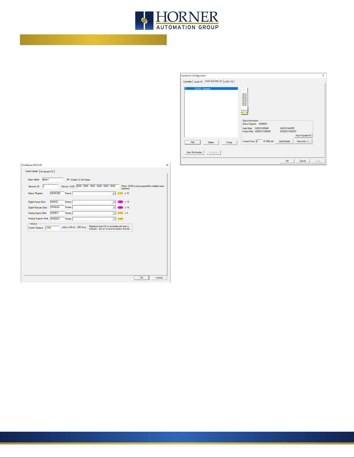
6. Click the “OK” button. This opens the following dialog:
• Base Name – any descriptive text (up to 15 characters)
• Enable OCSIO - When this option is checked Input/Output
data from the host controller will get transmitted to OCSIO.
If the option is unchecked Input /Output data will NOT get
transmitted to OCSIO but communication between the Host
controller and OCSIO will be healthy
• Network ID – unique CsCAN ID (1-79 decimal)
• Device UUID - Each OCSIO base requires a Unique ID to
establish communication with the host controller. In case
of Single Base OCSIO entering UUID is not required, host
controller can automatically assign that. In case of Multiple
base configurations, it is Mandatory to enter UUID of each
base.
• Status Register – Location where fifteen consecutive words
are reported
• Digital Inputs / Digital Outputs / Analog Inputs / Analog
Outputs Start – starting locations for each type of I/O for
this base. Be careful to choose starting addresses that do
not conflict with OCS built-in I/O mapping.
• Comm Timeout – Maximum amount of time the
HE959CNX116 will wait to act on a communications timeout
(40 to 255000ms)
7. After entering all the required information (above), click “OK”.
At this point, the following Hardware Configuration dialog will
appear:
8. Now modules can be added via the “Add Module” button. As
I/O modules are added the Input Map, Output Map, and Current
Draw are updated, showing the accumulated I/O Module Informa-
tion. More details regarding each module can be viewed via the
“More Info” button.
9. If the OCS-I/O base and I/O modules are properly connected
and powered up, and if Cscape currently has communications to
the OCS, the “Auto Populate IO” button may be used to recognize
all modules installed on this OCS-I/O base.
10. Right clicking on an I/O module will allow detailed configura-
tion to be performed, as follows:
a. Digital Input modules can be configured to update
on a change of state (typical) or periodically (rare). Input
filtering can also be adjusted from the default of 1mS.
b. Digital Output modules can optionally be configured
to hold last state in Stop/Idle mode.
c. Analog Input modules can be configured with an
update rate of 10mS to 255 seconds. Analog Inputs also
have configurable data type and range which varies by
module type.
d. Analog Output modules have configurable type and
range, and also can have Stop/Idle behavior adjusted to
Hold Last State, or go to Minimum (default), Medium or
Maximum value.
11. Press “OK” to complete the process.

MAN1175-01-EN
Indianapolis, USA | Cork, Ireland | Calgary, Canada | Bangalore, India | Oakleigh, Australia | Tianjin, China | Esteio, Brazil
Please visit our website for a complete listing and to learn more about certified Horner Automation products.
This document is the property of Horner Automation Group, and is subject to change.
5 STATUS REGISTERS
Register 16 15 14 13 12 11 10 9 8 7 6 5 4 3 2 1
1 IOE CME
2 IOCS WDG TRIP
3 Reserved NO_
CFG
LIFE
ERROR*
ALME ALM1** ALM0** DI2
US
DI1 US OFFLINE PUP
4 IO Base Net ID
5 IO Base Type
6 IO Base Scan Rate
7 IO Base Watchdog Trip Count
8 to 15 Firmware Version
CME- Each bit (bi1-bit8 ) represents configuration mismatch error of each IO Modules (Module 1 to Module 8)
IOE – Each bit (bit9 – bit 16) represents IO modules error (Module 1 to Module 8)
WDG TRIP – IO base watchdog trip count
IOCS- Each bit (bit9 – bit 16) represents IO modules calibration status (Module 1 to Module 8)
PUP – Power up error (sticky bit)
OFFLINE – OCSIO is offline
DI1 US - High when Digital input 1 is in undefined state
DI2 US – High when Digital input 2 is in undefined state
e.g: If 24V input range is selected then DI1 US bit set if voltage is between 8V to 16V.
ALME- Alarm Error
ALM1 – Alarm bit** See table below
ALM0 – Alarm Bit** See table below
LIFE ERROR* – Sticky bits must be reset by the user or program to re-arm those notifications.
NO CFG – OCSIO configuration status
ALE ALM1 ALM0 Alarm
1 0 0 Low-Low (LL)
0 0 1 Low (L)
0 0 0 Normal
0 1 0 High (H)
1 1 1 High-High (HH)
page 6 of 8

MAN1175-01-EN
Indianapolis, USA | Cork, Ireland | Calgary, Canada | Bangalore, India | Oakleigh, Australia | Tianjin, China | Esteio, Brazil
Please visit our website for a complete listing and to learn more about certified Horner Automation products.
This document is the property of Horner Automation Group, and is subject to change.
page 7 of 8
6 DIAGNOSTIC LED INDICATORS
LED Indicators
Status Power OK ()MS NS
V+ Power Applied ON ANY ANY ANY
Self-Test FAIL ON ANY OFF ANY
Self-Test PASS ON ON ANY ANY
Network Normal ON ON ON ON
Duplicate Net ID ON ON ON OFF
Configuration Mismatch ON Flash (1Hz) ON Flash (1Hz)
OCS Stop Mode/Communication Timeout ON ON ON Flash (1Hz)
OCS Run Mode ON ANY ANY ANY
Onboard I/O Fault ON OFF ON ON
Invalid Dynamic Configuration ON Flash (1Hz) ON ON
Power Up/ Waiting to be Configured ON ON Flash (1Hz) Flash (1Hz)
LED Indicators for Individual I/O Channels
I1 Digital Input-1 active
I2 Digital Input-2 active
Q1 Digital Output-1 active
Q2 Digital Output-2 active
AI1 Analog Input Active *
AQ1 Analog output Active
NOTE: Channel LED will be in OFF state if it is disabled
from Cscape configuration
*NOTE:
• LED will be ON during Normal operations.
• Analog Input channel configured as mA, Volts or
mV LED will be OFF till the input signal is 0+0.2%
• Analog Input channel configured as PT100,
PT1000 LED will be OFF if open circuit is detected,
LED will be ON during Normal operation
• Analog Input channel configured as Thermocouple
Input LED will be ON if the channel is Enabled.
Table of contents