Hortitek LMU User manual

LIGHT MANAGEMENT UNIT
USER GUIDE

HORTITEK® LIGHT MANAGEMENT UNITS (LMU)
Enables gardeners to safely and easily control their grow lights.
The LMU serves 3 main functions:
• Time Control: Hortitek LMU can simulate any light cycle by using the 24-Hour timer.
• Power Control: Hortitek LMU can control, distribute and protect the load by using the
circuit breakers.
• Time Delay: This feature reduces the startup current and prevents voltage drop in the
network by staggering the ignition of the load.

KEY FEATURES
LMU LEGEND
24-HOUR TIMER
LIVE SOCKETS
OVERLOAD PROTECTION
ACTIVE & PASSIVE COOLING
HIGH QUALITY MATERIAL
HANGING &
MOUNTING OPTIONS
INTELLIGENT SOFT START
SELECTOR SWITCH
L1242
LMU24 + 4LIVE - 12ON / 12OFF OR 24ON + TIME DELAY
1 PHASE - 100A MAX - 80A CONTINUOUS - 240V - 50Hz
1
2
3 4 5 6
7 8 9 7 10
1- L1242: MODEL NUMBER
2- LMU24: NUMBER OF TIMED SOCKETS
LMU24 = 24 timed sockets. These timed sockets
control the light cycle of connected ballasts using
the 24-Hour Timer.
3- 4LIVE: NUMBER OF LIVE SOCKETS
4LIVE = 4 always-on LIVE sockets. These can be
used for fans, pumps, heaters or other
appliances.
4- 12ON / 12OFF: SIDE A / SIDE B OPERATION
This indicates the number of HALF ON / HALF OFF
sockets. 12ON / 12OFF = 12 times sockets are on
while 12 time sockets are off.
5- 24ON: ALL ON OPERATION
This indicates the number of ALL ON sockets.
24ON = 24 timed sockets will be on at once.
6- TIME DELAY: LMU IS EQUIPPED WITH TIME
DELAY.
7- 1 PHASE/240V: INCOMING VOLTAGE TYPE
This indicates the incoming voltage type of the
LMU, either 1 PHASE/240V or 3 PHASE/415V.
8- 100A MAX: MAXIMUM PEAK CURRENT RATING
This is the maximum load that can be safely
supported by the LMU. This maximum should
only be sustained for 4 hours.
9- 80A CONTINUOUS: MAXIMUM CONTINUOUS
CURRENT RATING
This is the maximum load that can be safely
supported by the LMU in continuous, 24-hour
operation.
10- 50Hz: INCOMING POWER FREQUENCY
Both 1 PHASE and 3 PHASE power have a
frequency of 50Hz in Australia and New Zealand.

L1205
LMU12+4LIVE-12ON
1PHASE-63AMAX-50ACONTINUOUS-240V-50HZ
SET UP & OPERATION
1
All Lamps will turn ON
Note: To prevent a voltage drop in the
network, Hortitek LMUs are equipped
with Time Delay.
This function staggers the ignition of
lights sequentially by 1-2 minutes.
IMPORTANT NOTES
• Do not cover or obstruct ventilation openings.
• Do not obstruct the Circuit Breakers with cables or other
objects.
• Do not store or operate the LMU outdoors or in a moist
environment, or near water sources.
• To prevent exposing the LMU to high ambient
temperatures (above 40°C), avoid placing the LMU in the
same room as heat sources such as ballasts or lights.
• Sudden voltage increases can cause damage to your
LMU and related appliances. If you live in an area at high
risk of lightning strikes, it is highly recommended that you
have a licensed electrician install a surge protection
device between the LMU and the Incoming Mains Supply
cables.
The surge protection device should be of the same
current rating as the Main Circuit Breaker on the
switchboard. (All LMU’s are equipped with a fuse
and MCB’s to protect the unit and attached devices
from short circuits and overloading).
• Dust build-up in unused sockets on the LMU can
lead to reliability issues. Always ensure that unused
sockets are sealed off to maximise the longevity of
your Hortitek LMU.
• Always use a licensed electrician to connect your
Hortitek LMU to the Mains Power Supply.
Turn off all Circuit Breakers (CB) by
pushing the switches downwards.
Connect and tighten the supply
Earth to the LMU Earth lug.
If applicable, set your desired LMU
function using the selector switch
(Refer to selector switch guide).
Set your desired light cycle by
adjusting the 24-hour timer (Refer
to 24-hour timer guide).
Have a licensed electrician connect
the LMU supply wires to the
incoming power supply using the
wire connectors provided.
Note: When connecting the LMU supply wires,
ensure that the incoming power supply wires
are of equal or greater size/gauge.
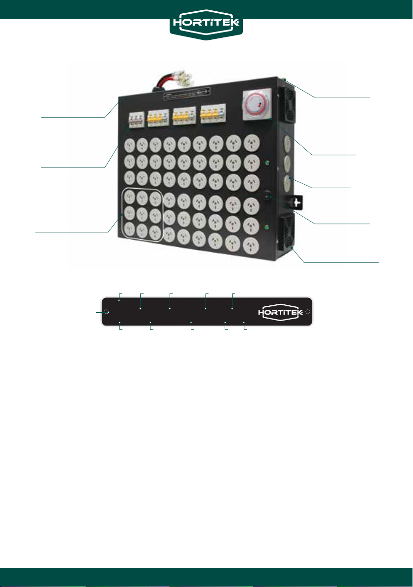
L1242
LMU24 + 4LIVE - 12ON / 12OFF OR 24ON + TIME DELAY
1 PHASE - 100A MAX - 80A CONTINUOUS - 240V - 50Hz
L1242
LMU24 + 4LIVE - 12ON / 12OFF OR 24ON + TIME DELAY
1 PHASE - 100A MAX - 80A CONTINUOUS - 240V - 50Hz
MAIN
4
Connect all lamps to their respective
ballast, then connect the ballasts to the
LMU. Refer to the Lamp Distribution
Guide provided with your LMU to prevent
Overloading.
5
8
Turn ON the Main Circuit Breaker, next
turn on all other Circuit Breakers
one-by-one with a 10-second delay
between each, by pushing the switches
upwards.
6
32
A or B
A & B
Connect the control cable to the
PowerPoint and turn the switch ON.
7

Hortitek LMU’s 24-hour timer has 2 modes
Automatic and Permanent
PERMANENT MODE
To override the timer, set the timer switch to
Permanent Mode, this disregards the position of
any pins and sets all LMU sockets on.
AUTOMATIC MODE
Ensure the timer switch is on Automatic Mode.
This is the default and recommended setting
when using Hortitek LMU.
Setting the time: Turn the timer clockwise and
point the arrow on the face to the current time.
The Timers on Hortitek LMU’s have 96 red pins,
with each pin representing 15 minutes (4 pins = 1
hour). Use the red pins to set your 24-hour cycle.
When pins are facing inside, the sockets
connected to the timer A and B are off; and when
the pins are facing outside, they are on. This can
be used to simulate day and night such as 12
hours on, 12 hours off continuously.
The operation of the Timer depends on which
function the Hortitek LMU selector switch is set.
SELECTOR SWITCH GUIDE 24-HOUR TIMER GUIDE
For models that include a Selector Switch, it can
be used to control how many lights are active in
each on/off cycle. That is, gardeners can choose to
have half of their lights on, while the other half
are off.
This is highly useful in situations where gardeners
have more than one grow room set up and wish to
keep them on different light cycles to prevent
excessive power draw. Other benefits include
reduced heat generation, or simply to maximise
their usage of their energy supply with lights
operating all day as opposed to only half the day.
SELECTOR SWITCH - HALF ON / HALF OFF (A or B)
In the I position: The Timer will turn Side A sockets
on and Side B sockets off. When the Timer turns
Side B sockets on, Side A sockets will turn off.
SELECTOR SWITCH - ALL ON (A & B)
In the O position: The Timer will turn both Side A
sockets and Side B sockets on simultaneously. It
will also turn both Side A sockets and Side B
sockets off simultaneously.
A Selector Switch will alter the way in which the
Timer is used to control the light cycle. Further
explanation is given in the following pages.
SIDE A
SIDE B
SELECTOR
SWITCH
I: Permanent O: Automatic
1
CB CB CB
L1244
LMU54 + 6LIVE-27ON /27OFF +TIMEDELAY
3PHASE -80A MAX- 64ACONTINUOUS-240V- 50HZ

SELECTOR SWITCH -
ALL ON
Red pins facing outside will cause all sockets to
turn on.
Red pins facing inside will cause all sockets to turn
off.
For example, the Timer below shows 24 pins facing
Inside, and 72 pins facing Outside. When the Timer
is on the Outside pins, all sockets will be on for 18
hours. When the Timer is pointing to the Inside
pins, all sockets will be off for 6 hours.
FACING
INSIDE
FACING
OUTSIDE
SELECTOR SWITCH -
HALF ON / HALF OFF
Red pins facing inside will cause Side A to turn off,
and Side B to turn on.
Red pins facing outside will cause Side A to turn
on, and Side B to turn off.
For example, the Timer below shows 48 pins
facing Inside, and 48 pins facing Outside. This
means that one side (Side A or Side B) is on for 12
hours, while the other side is off for 12 hours.
FACING
INSIDE
FACING
OUTSIDE
A or B
A & B

A- If using 315/400W lamps, the maximum number
of lamps allowed to this socket is 2.
B- If using 600/630W lamps, the maximum number
of lamps allowed to this socket is 1.
C- If using 800W lamps, the maximum number of
lamps allowed to this socket is 1.
D- If using 1000W lamps, the maximum number of
lamps allowed to this socket is 1.
• If using 600/630W lamps, the maximum
number of lamps allowed to this LMU’s timed
sockets are 24pcs and 6A maximum for the live
sockets.
HOW TO READ THE DISTRIBUTION GUIDE
The Distribution Guides included with all Hortitek
LMU’s have been specially designed to distribute
the power evenly on the LMU and protect against
overloading. It eliminates the guesswork in setting
up your lighting system.
Each lamp has been colour-coded:
EXAMPLE:
MAXIMUM RECOMMENDED LIGHTING ARRAGEMENT
TIMED SOCKET
LAMP
36pcs
24pcs
315/400W 2.1A
600/630W 3.2A
800W 4A
1000W 5A
20pcs
16pcs
6A
6A
6A
5A
CURRENT MAX. QTY.
LAMPS
MAX. AMPS FOR
LIVE SOCKETS
A
B
C
D
L1209
LMU24 +4LIVE- 12ON /12OFFOR24ON+TIMEDELAY
1 PHASE- 80A MAX- 64A CONTINUOUS- 240V- 50Hz
- 240V - 50HZ
CB
M
A
I
N
CB
1
CB
2
CB
3
CB
4
CB
5
L
I
V
E
CB
1
CB
2
CB
3
CB
4
CB
5
24ON
www.hortitek.com
MAXIMUM RECOMMENDED LIGHTING ARRANGEMENT
315W 315W400W 400W600W1000W 600W 600W800W
IMPORTANTNOTES - LMU TO BE INSTALLED BY
LICENSED ELECTRICIAN
- Faulty magnetic ballast capacitor connected in
parallelcan significally increase amps by up to 80%.
- For electronic ballasts, lamp distribution table
provided is considering voltage @240V. Electronic
ballasts have broad operating voltages (100~ 280V).
Decreasein voltage will increase amps.
28pcs
20pcs
LAMP
315/400W 2.1A
600/630W 3.2A
800W 4A
1000W 5A
16pcs
12pcs
6A
5A
5A
5A
CURRENT MAX. QTY.LAMPS MAX. AMPSFOR
LIVE SOCKETS WHEN USING VARIOUSWATTAGELAMPS ON ONE LMU,
FOLLOWARRANGEMENT BELLOW
24ON
LMU - LIGHT MANAGEMENT UNIT LAMP DISTRIBUTION GUIDE
|
|
BLUE = 800W
YELLOW = 600/630WRED = 315/400W
GREEN = 1000W

SAFETY PRECAUTIONS TROUBLE SHOOTING
• Connecting more lamps than suggested in your
model’s lamp Distribution Guide may cause
overloading.
• If faulty ballasts are connected to the LMU, this
will increase the current (Amps) drawn and will
cause overloading.
• Overloading of the LMU causes high
temperatures within the unit and puts a lot of
strain on all of the components. As a result, it will
damage the LMU and decrease its service life.
• Do not mount the LMU in an enclosed space.
• Ambient temperatures for safe operation of the
LMU must be lower than 40°C.
When connecting a ballast to its socket on the LMU,
follow these steps:
• Turn off the related Circuit Breaker (CB) by
pushing the switch downwards.
• Connect the ballast to the Socket.
• Turn on the related Circuit Breaker (CB) by pushing
the switch upwards.
Always use a licensed electrician.
Please refer to the website for all the information
about Trouble Shooting.
For more information about Hortitek LMU’s refer to
hortitek.com/hortitek-lmu
Table of contents
Other Hortitek Lighting Equipment manuals
Popular Lighting Equipment manuals by other brands

LIVARNO LUX
LIVARNO LUX CORDLESS WORK LIGHT Operation and safety notes

Delta Light
Delta Light 300 90 135 Installation instruction

Hybrid+
Hybrid+ SIX BEAM user manual

GOAL ZERO
GOAL ZERO TORCH 500 user guide

HQ Power
HQ Power HQMH10005 user manual

Astral Pool
Astral Pool 01413 Installation and maintenance manual