Hoval HomeVent comfort FRT 251 User manual

United Kingdom
Hoval Ltd.
Northgate
Newark
Nottinghamshire NG24 1JN
Phone +44 1636 67 27 11
Fax +44 1636 67 35 32
Export
Hoval Aktiengesellschaft
Austrasse 70
LI-9490 Vaduz
Principality of Liechtenstein
Phone +423 399 24 00
Fax +423 399 24 11
Subject to modifi cations | EN
Operating Instructions
HomeVent®comfort FRT (251, 351, 451)
Comfort ventilation unit
4 216 974 / 02 - 09/19

4 216 974 / 022Subject to modications
TABLE OF CONTENTS
1. Key to symbols used .............................................................................................................................. 3
2. Safety instructions.................................................................................................................................. 3
3. Important information
3.1 Warranty...............................................................................................................................................................................3
3.2 Liability ................................................................................................................................................................................3
3.3 Guarantee ............................................................................................................................................................................4
4. Technical information
4.1 Description ..........................................................................................................................................................................4
4.2 Use .......................................................................................................................................................................................5
4.3 Application limits.................................................................................................................................................................6
5. Components
5.1 Ventilation unit.....................................................................................................................................................................6
5.2 Operator terminal ................................................................................................................................................................6
6. Commissioning
6.1 Installation inspection.........................................................................................................................................................7
6.2 Switching on........................................................................................................................................................................7
7. Maintenance
7.1 Supply air and extract air filter ...........................................................................................................................................7
7.1.1 Filter soiling....................................................................................................................................................................7
7.1.2 "Filter change" procedure ...............................................................................................................................................8
7.2 Prefilter ................................................................................................................................................................................8
7.2.1 Cleaning interval.............................................................................................................................................................8
7.2.2 Procedure.......................................................................................................................................................................9
7.3 Fuse change ........................................................................................................................................................................9
7.4 Spare parts ..........................................................................................................................................................................9
8. Logs
8.1 Plant logs...........................................................................................................................................................................10
8.2 Filter maintenance log.......................................................................................................................................................11

4 216 974 / 02 3
Subject to modications
KEY TO SYMBOLS USED AND SAFETY INSTRUCTIONS
1 Key to symbols used
i
Notice :
Important information.
Safety instructions:
Indicate an immediate hazard to persons.
Cautionary notes:
Indicate danger to machines and
installations.
2 Safety instructions
Persons performing work on the HomeVent®comfort
ventilation unit must have read and understood the
operating instructions before commencing work. The
unit must not be taken into operation until the air ducts
have been connected. Initial commissioning of a newly
installed system must only be carried out by a qualied
installer. The installation inspection must be carried out
by a qualied technician trained by Hoval.
In the event of danger:
Switch the unit o and cut o the power
supply.
In the event of a re:
Switch the unit o and cut o the power
supply.
i
Do not carry out any modications to the unit!
Otherwise, all legal claims will be
invalidated.
Opening the lter cover/prelter cover:
Switch the unit o rst and cut o the
power supply.
Opening the unit cover:
The unit is only allowed to be opened by
a qualied technician trained by Hoval.
3 Important information
3.1 Warranty
• The HomeVent®comfort ventilation unit is only
allowed to be operated within the dened
application limits.
• The HomeVent®comfort ventilation unit is only
allowed to be used for supply and extract air
handling of heated rooms.
• The pertinent laws, regulations and guidelines must
be complied with during installation and operation,
when performing maintenance and service work
and when disposing of the unit.
• The HomeVent®comfort ventilation unit is only
allowed to be operated in rooms and on premises
with replaces in compliance with the pertinent
country-specic laws, regulations and guidelines.
Flue gas from replaces must be routed o
separately.
• Do not drill into the housing of the HomeVent®
comfort ventilation unit.
The comfort ventilation unit is only allowed to be used
for the purpose for which it was designed and which has
been approved by Hoval. Any other use is
impermissible.
Application in the following areas is prohibited:
• Operation during the construction phase, due to the
high dust exposure.
• Use of the unit to dry out building shells and new
buildings
• Ventilation of several residential units.
• Ventilation of rooms with extremely high air humidity
levels, e.g. steam rooms, indoor swimming pools.
• Ventilation of rooms with extremely high air humidity
levels, e.g. saunas, indoor swimming pools.
• The ventilation of rooms with highly contaminated
extract air (ue gas, chlorine, air containing high
amounts of grease, explosive extract air), e.g.
rooms in the catering industry, swimming baths,
rooms in which chemicals are stored.
• The conveyance of air contaminated with
aggressive vapours and abrasive substances.
• The extraction of ue gas from replaces.
3.2 Liability
• The application limits are stated below. Any other
use is deemed to be improper use and can lead to
injury to persons or damage to the comfort ventilati-
on unit. The manufacturer cannot be held liable for
any such damage.
• The manufacturer accepts no liability for damage
resulting from:
- Failure to observe the safety, operating and
maintenance instructions contained in these
operating instructions.
- Performance of work on the unit not described
in these operating instructions and not
expressly approved by the manufacturer.
- Installation of spare parts (including lters) not
supplied by the manufacturer.
- Normal wear and tear.
• The general business terms and conditions of Hoval
apply. See: www.hoval.com
• For details concerning service agreements, please
contact Hoval Customer Service. You will nd the
addresses on the back page of this manual.

4 216 974 / 024Subject to modications
3.3 Guarantee
With the acquisition of a Hoval unit, you also obtain
comprehensive warranty cover under the Hoval terms
of warranty. This warranty is, however, dependent on ob-
servance of the operating instructions and on complian-
ce with the applicable legal regulations. Non-compliance
with the above will invalidate all liability and warranty
claims against Hoval.
4 Technical information
4.1 Description
Exhaust air
Fresh air
Extract air Supply air
Technology room
Bedroom,
Living room
Bath, WC
Kitchen
Energy recovery
The built-in enthalpy recovery unit withdraws energy
from the extract air and transfers it to the supply air.
This enables the intelligent (temperature) and the latent
(humidity) energy to be transferred. The transmission
performance is regulated between 0 and 100%
depending on the outdoor temperature.
The advantages of the enthalpy recovery unit are:
IMPORTANT INFORMATION AND TECHNICAL INFORMATION
• Temperature eciency up to 90%
• Degree of humidity recovery up to 95%
• Transmission performance can be adjusted
continuously
• No preheating required (down to -20°C)
• No condensation
• No bypass required
Air ltration
The fresh air goes through two cleaning stages,
ensuring the highest standard. A ne-meshed prelter
(washable) at the entry of the unit prevents insects, lea-
ves, etc. from reaching the unit. Before the fresh air lea-
ves the unit, it ows through a high-capacity ne pollen
lter (ePM1.050%). In addition, an activated carbon lter
can be installed on the supply air side (optional). The
operator receives a message when it is time to change
the lter.
Air delievery
Two backward-curved centrifugal fans with EC direct
current motors deliver the air. The rotating wheel made
of high-tech composite material is produced in one
piece with optimised uid mechanics, and ensures quiet
operation of the unit. The electronics built into the motor
enable the air volumes to be nely regulated.
Fan failure:
If a fan fails - supply and/or extract air -
the unit switches o. The state is displa-
yed on the operator terminal. Contact the
HomeVent specialist near you.
Suitability for winter
Due to the built-in enthalpy recovery unit, no condensate
is formed in the unit. Ice formation is not possible. No
preheating (electric air heater) is necessary for outdoor
temperatures down to -20 °C. The air volume ratio
between the supply air and extract air is not changed.
Summer operation
The energy recovery is reduced to a minimum according
to the outdoor temperature. This enables night cooling
(free cooling) in the summer as well as when the sea-
sons change. It is not necessary to arrange for a bypass
via dampers and a drive. In addition, the CoolVent opti-
on can actively recover cold in
air-conditioned buildings. The hot fresh air is cooled and
if necessary dried with the air-conditioned extract air.
Installation
The HomeVent®comfort ventilation unit is characterised
by a compact design. Dierent air connections are pos-
sible using the three variable acoustic insulating boxes.
No condensate accrues in the unit.

4 216 974 / 02 5
Subject to modications
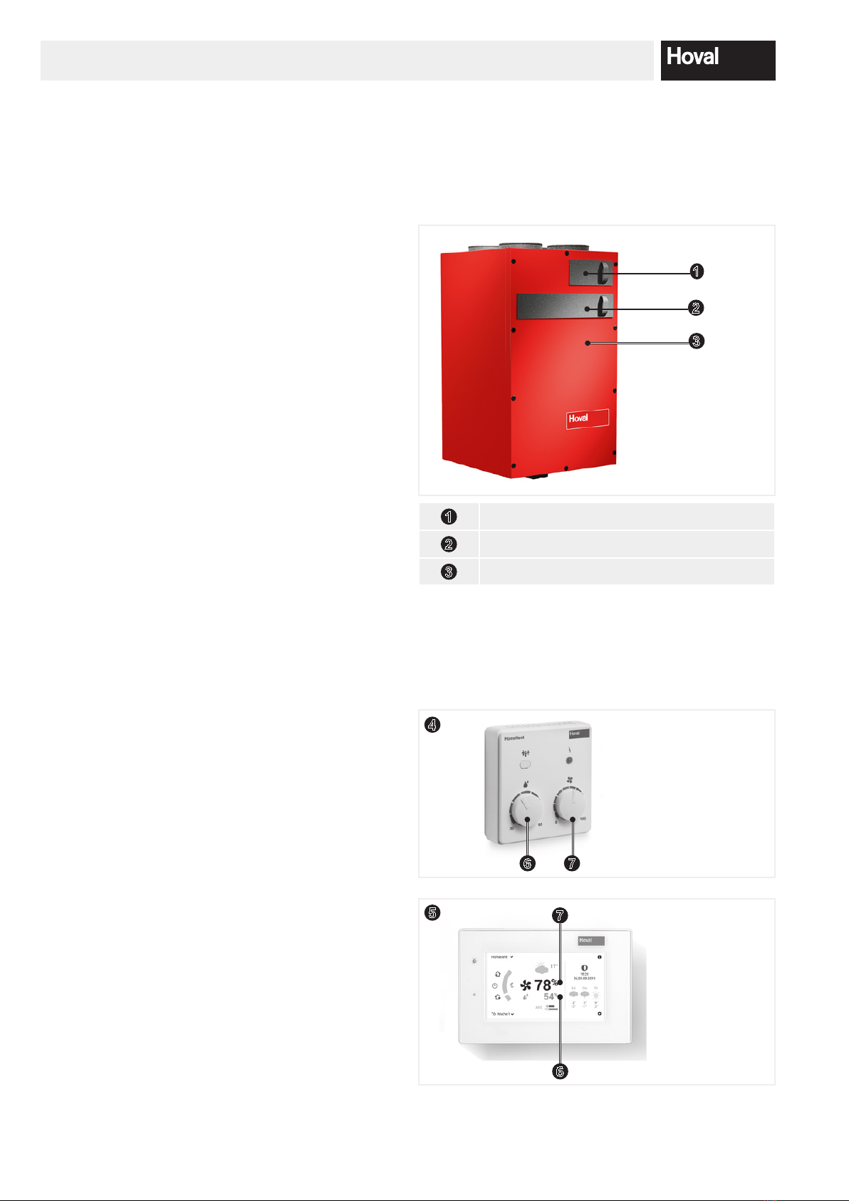
Standard operator terminal BG02 E
The operator terminal is suitable for on-wall mounting.
The target air volume and the maximum air humidity can
be set with two rotary knobs. With the party button, the
air volume can be increased for a limited period of time.
Connection to the HomeVent®comfort ventilation unit via
RJ45 plug connection. The unit can also be installed in a
secondary room.
TopTronic®E room control module comfort plus
The TopTronic®E room control module comfort plus is
available either with a black or white design.
Operable via colour touchscreen (4.3-inch). The connec-
tion to the HomeVent®comfort ventilation unit is made
via RJ45 plug connection or plug terminals (max.
0.75 mm2). The unit can be installed on the wall with an
on-wall mounted frame or with a wall-mounting plate and
ush-mounted boxes. The TopTronic®E room control
module carries out the following
functions:
• Operation of all Hoval units connected to the bus.
• Authorisation management for operation.
• Ecient control of the ventilation system by working
with day programmes.
• Selection between dierent start screens possible
during commissioning.
• Customer-specic congurable screen for displaying
the following elements: date, time, target air volume in
%, maximum target humidity in %, active day or week
programme, display of the current air quality inside
and outside the building based on a colour marking
(only in combination with VOC air quality sensors),
display of the current weather or weather forecast
(only possible in combination with TopTronic®online),
phases of the moon.
Control error:
If the unit control fails, the unit switches
o. The state is displayed on the operator
terminal. Contact the HomeVent specialist
near you.
Air quality
Optionally, one or two VOC air quality sensors can be
installed in the unit during commissioning. In addition, an
activated carbon lter can be installed on the supply air
side as an option. The VOC air quality sensor(s) cont-
inuously monitor(s) the air for volatile organic compo-
nents and regulate the air volume that is supplied or ex-
tracted via the speed of the fans. This results in optimal
air quality in the building with minimal energy input.
VOC air quality sensor on extract air side: The extract
air is continuously monitored for odours, tobacco smoke,
cleansing agents, etc. If the concentration of the extract
air exceeds a certain value, the air volume is increased
correspondingly.
VOC air quality sensor on fresh and extract air side: The
extract and fresh air is continuously monitored for odours,
tobacco smoke, cleansing agents, etc. If the
TECHNICAL INFORMATION
concentration of extract air exceeds a certain value, the
air volume is increased correspondingly.
If the concentration in the fresh air exceeds a certain
value, the air volume is reduced correspondingly. The
sensor registering the higher value takes priority. The
sensitivity can be set to one of 3 stages. On the
TopTronic®E room control module comfort plus, the air
quality is displayed by a bar for the extract air and a bar
for the fresh air, which will either be green (good air),
orange (slightly contaminated air) or red (bad air).
The activated carbon lter can be inserted in place of
the standard supply air lter. This is a high-capacity lter
(ePM1.050%) with high eciency against particles (pol-
len, ne dust, etc.) and against gaseous pollutants and
odours (agriculture, trac, etc.).
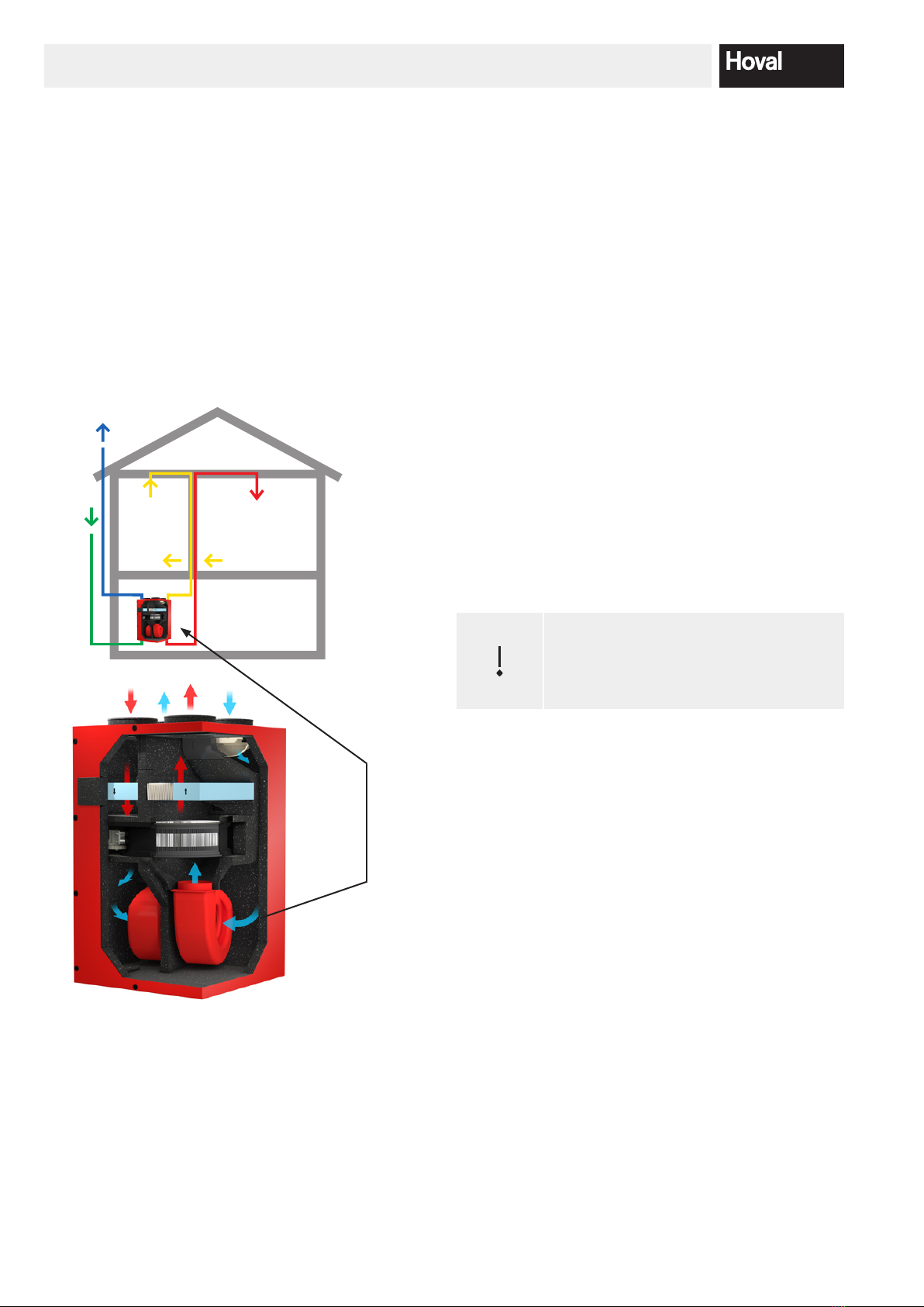
Cooling
The warm fresh air can be cooled using the CoolVent®
option. However, this requires an air-conditioning system
to be present in order to provide the necessary cooling
in the room. The enthalpy recovery system extracts heat
from the warm fresh air and feeds it to the cold extract
air. The necessary output of the air-conditioning system
is thereby reduced. The eciency for this process is
85%. The CoolVent function is an option which must be
activated during commissioning.
4.2 Use
Settings on the operator terminal
The operator terminal allows you to adjust your
HomeVent®comfort ventilation system to suit your
needs. Using the operator terminal or module, it is
possible to set the basic ow rate at which the
ventilation unit should always be operated as a
minimum. Furthermore, the target humidity value can be
selected. If this is exceeded in the room, the ow rate
of the ventilation unit is increased. Please bear in mind
that, especially during the change of seasons, setting a
low target humidity value can result in a high volumetric
current and thus noise. Detailed operating instructions
were enclosed with your operator termina
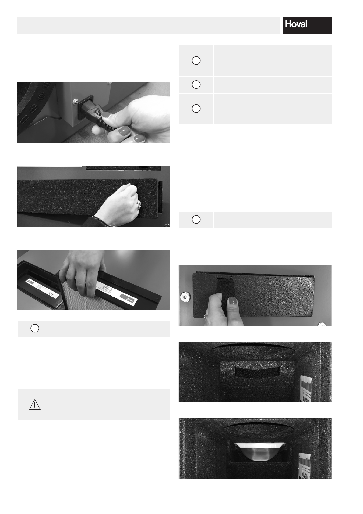
Functional check
Reliable and safe functioning of the HomeVent®com-
fort ventilation unit and optimum eciency can only be
guaranteed if the unit is serviced regularly. Please also
regularly check the other components of your comfort
ventilation system, such as the fresh air intake, supply
and extract air ports and exhaust air grille, Supply and
extract air openings and exhaust air grille.

4 216 974 / 026Subject to modications
TECHNICAL INFORMATION, COMPONENTS AND COMMISSIONING
Opening the windows
As a rule, you will not require heating in summer and
thus no heat recovery via your comfort ventilation unit.
HomeVent®comfort ventilation unit. You can open doors
and windows as you wish. However, bear in mind that
pollen, insects and dust can enter the house through
open doors and windows.
If you open the windows in winter or during the heating
season, you lose the benets of your HomeVent®
comfort ventilation system. Valuable energy escapes
through the windows. The humidity contained in the
outgoing air cannot be recovered, meaning that the
room and becomes drier. Your comfort ventilation
system provides a constant supply of fresh air for your li-
ving area. Your comfort ventilation unit recovers both the
heat and the moisture contained in the air. Your comfort
ventilation system provides a constant supply of fresh air
for your living area. Your comfort ventilation unit reco-
vers both the heat and the moisture contained in the air.
Absence
If you are away for a prolonged period, set your comfort
ventilation to an output of 15% and keep outside doors
and windows closed - in particular in winter so that no
heat is lost. Never switch your comfort ventilation
system o completely in winter.
4.3 Application limits
Application limits for unit setup, weather-protected
(EN 60721-3-3)
3K5 as per EN 50090-2-2
• Ambient temperature -16…45 °C
• Ambient humidity max. 12 g/kg
• Dew point temp. in installation room < 15 °C
air conditions
(Moderate outdoor climate EN 60721-2-1)
• Fresh air intake temperature -20…40 °C
• Fresh air intake humidity 5…95 % r.F.
• Extract air temperature 5…35 °C
• Extract air humidity 5…80 % r.F.
• Extract air humidity max. 12 g/kg
5 Components
5.1 Ventilation unit
Comfort ventilation unit:
2
3
1
1Supply air and extract air lter
2Access panel
3Prelter cover
5.2 Appareil de commande
The HomeVent®comfort ventilation unit is operated
via an operator terminal. You can choose between two
operator terminals.
4
6 7
or
57
6

4 216 974 / 02 7
Subject to modications
4Operator terminal BG02 E
5TopTronic® E room control module comfort
plus
6Target value max. air humidity
7Air quantity in %
6 Commissioning
6.1 Installation inspection
Please check the following points:
• The HomeVent®comfort ventilation unit must be
mounted securely and vibration-free on the wall,
ceiling or oor.
With ceiling installation:
Beware of falling parts.
• The HomeVent®comfort ventilation unit must be
mounted securely and vibration-free on the wall or
the original Hoval device base.
• One silencer each must be tted for supply and
extract air. A silencer may also be necessary in the
fresh and exhaust air, depending on the positioning
of the outlets. When using one of the three acoustic
insulating boxes, all supply and exhaust air lines are
insulated.
• The comfort ventilation unit must be connected in
accordance with the rules of ventilation engineering.
• Fresh and extract air lines must be thermally
insulated to prevent vapour diusion.
• If the comfort ventilation unit is located in an
unheated room, the supply and extract air lines
must thermally insulated.
• The ducts must be leak-tight.
• Check the supply air outlets for dirt build-up and
clean them if necessary.
• Extract air points must be free and clean.
• The fresh air intake must be clean and
unobstructed.
• The lters must be clean.
• The HomeVent®comfort ventilation unit must be
connected to the mains.
• Electrical connecting lines must be intact.
• The comfort ventilation unit must be inspected and
serviced regularly. The cleaning and maintenance
intervals depend to a great extent on the running
time and the degree of contamination in the ambient
air (e.g. dust, trac etc.).
• The HomeVent® operator terminal must be
connected to the comfort ventilation unit.
6.2 Switching on
• Connect the mains plug of the HomeVent®comfort
ventilation unit to the device and in the socket.
• Set the operator terminal to the desired operating
mode.
7 Maintenance
The comfort ventilation unit must be inspected and ser-
viced regularly. The cleaning and maintenance intervals
depend to a great extent on the running time and the
degree of contamination in the ambient air (e.g. dust,
trac etc.).
i
Thorough cleaning of the HomeVent®
Comfort ventilation unit by Hoval Cus-
tomer Service or an installer trained by
Hoval.
i
Conclude a service agreement with Ho-
val, and your HomeVent®comfort ven-
tilation unit will be serviced regularly by
Hoval Customer Service.
7.1 Supply air an extract air filter
Caution:
Do not operate the comfort ventilation unit
unless the lters are tted!
i
Replace the lters after the pollen season
if you have a pollen allergy.
Filter message on operator terminal:
In order to ensure optimal operation,
lters must be replaced when a lter mes-
sage appears on the operator terminal.
The interval depends on the lter load.
7.1.1 Filter soiling
The supply air and extract air lters are time-monitored.
The end of the set operating time is displayed on the
operator terminal. The lter replacement interval can be
adapted to local conditions.
• Operator terminal BG02 E:
Operating mode display LED lights up orange.
• TopTronic E® room control module comfort plus:
operating mode display LED lights up orange and is
supplemented by a warning triangle on the display.
COMMISSIONING AND MAINTENANCE

4 216 974 / 028Subject to modications
7.1.2 "Filter change" procedure
1. Disconnect the HomeVent®comfort ventilation
unit power plug.
2. Pull out lter cover.
3. Pull out soiled lters. Remove lter support.
i
Dispose of the soiled lters immediately
after exchange.
4. Clean the lter chamber by hand or with a
vacuum cleaner.
5. The lter support does not have to be
reinserted.
Caution:
Observe the correct air ow direction
when inserting the lters (arrows on the
lter)!
6. Insert cover and push on rmly.
7. Connect the HomeVent®comfort ventilation
unit power plug.
MAINTENANCE
i
• The lters are not reusable
(washable).
• The lters are 100 % incinerable
(residual waste).
i
Make a note of the date when you
replaced the lters on the log sheet.
i
Order new lters when you have replaced
the old ones to ensure that you can
change the lters without delay the next
time this becomes necessary.
7.2 Prefilter
The prelter is inside the unit on the fresh air inlet.
7.2.1 Cleaning interval
The prelter should be cleaned regularly for hygiene
reasons.
i
Make a note of the date when you
cleaned the lters on the log sheet.
7.2.2 Procedure
1. Pull out both prelter cover.
2. Pull out, wash and dry the soiled prelter.
3. Pull out the dirty prelter, wash and dry.

4 216 974 / 02 9
Subject to modications
MAINTENANCE
i
If the prelter is damaged, please order a
new lter.
4. Clean the lter chamber by hand or with a
vacuum cleaner.
5. Slide in the cleaned lters.
6 . Push in both prelter cover.
7. Insert prelter cover.
7.3 Fuse change
1. Pull out plug.
Caution high voltage!
2. Place screw driver, pull out insert.
3. Change fuse (a replacement fuse (a) is
available in the unit).
a
4. Slide in insert
5. Insert plug
7.4 Spare parts
i
Use only genuine Hoval accessories. You
will nd the ordering addresses on the
back page of this manua.
Designation Filter class Art.No.
Supply air lter
pollen ne cassette lter
ISO
ePM1.050%
5043 550
Supply air active carbon lter
ACF high-output SA lter alter-
native to supply air lter ZF-200
ISO
ePM1052%
5043 778
Extract air lter AF
coarse particulate cassette lter
ISO
ePM1050%
5043 611
i
Order the spare parts directly at
www.hoval.com

4 216 974 / 0210 Subject to modications
LOGS
8 Logs
8.1 Plant logs
Installer
...........................................................................................................................................................................
...........................................................................................................................................................................
...........................................................................................................................................................................
...........................................................................................................................................................................
...........................................................................................................................................................................
Electrician
...........................................................................................................................................................................
...........................................................................................................................................................................
...........................................................................................................................................................................
...........................................................................................................................................................................
...........................................................................................................................................................................
Hoval Customer Service
(see back page of this manual)
...........................................................................................................................................................................

4 216 974 / 02 11
Subject to modications
8.2 Filter maintenance log
Please make a note of the actions you have carried out in the log below! E.g.: When you have inspected the sup-
ply air lter, circle the 'I' in the supply air lter column and enter the date on which the inspection was carried out. If
servicing tasks are performed by several persons, the person who carried out the task should enter their name in the
last column in case any questions arise later.
I = Inspection R = Replacement C = Clearing
No. Supply air
lter
Extract air
lter
Prelter Comment Date Carried out by
1 I / R I / R I / C heavy dirt build-up 24.10.2011 K. Müller
2 I / R I / R I / C
3 I / R I / R I / C
4 I / R I / R I / C
5I / R I / R I / C
6 I / R I / R I / C
7 I / R I / R I / C
8 I / R I / R I / C
9I / R I / R I / C
10 I / R I / R I / C
11 I / R I / R I / C
12 I / R I / R I / C
13 I / R I / R I / C
14 I / R I / R I / C
15 I / R I / R I / C
16 I / R I / R I / C
17 I / R I / R I / C
18 I / R I / R I / C
19 I / R I / R I / C
20 I / R I / R I / C
21 I / R I / R I / C
22 I / R I / R I / C
23 I / R I / R I / C
24 I / R I / R I / C
25 I / R I / R I / C
LOGS

United Kingdom
Hoval Ltd.
Northgate
Newark
Nottinghamshire NG24 1JN
Phone +44 1636 67 27 11
Fax +44 1636 67 35 32
www.hoval.co.uk
Principality of Liechtenstein
Hoval Aktiengesellschaft
Austrasse 70
LI-9490 Vaduz
Phone +423 399 24 00
Fax +423 399 24 11
www.hoval.com
Switzerland
Hoval AG
General Wille-Strasse 201
CH-8706 Feldmeilen
Phone +41 44 925 61 11
Fax +41 44 923 11 39
www.hoval.ch
Germany
Hoval GmbH
Humboldtstrasse 30
DE-85609 Aschheim-Dornach
Phone +49 89 92 20 97-0
Fax +49 89 92 20 97-77
www.hoval.de
Austria
Hoval Gesellschaft mbH
Hovalstrasse 11
AT-4614 Marchtrenk
Phone +43 50 365 - 0
Fax +43 50 365 - 5005
www.hoval.at
Italy
Hoval s.r.l.
Via XXV Aprile 1945, 13/15
IT-24050 Zanica (BG)
Phone +39 035 666 1111
Fax +39 035 526 959
www.hoval.it
France
Hoval SAS
Parc d’Activité de la Porte Sud
Bâtiment C - Rue du Pont au Péage
FR-67118 Geispolsheim
Phone +33 388 60 39 52
Fax +33 388 60 53 24
www.hoval.fr
Responsibility for energy and environment
This manual suits for next models
2
Table of contents
Other Hoval Fan manuals