The blind rivet nut setting tool must only be used for the purpose of
setting blind rivet nuts as described in these operating instructions.
●Never overload the blind rivet nut setting tool; work within the specified working
capacity.
●Never use the blind rivet nut setting tool in a humid or wet environment or close to
flammable liquids or gases. Danger of Explosion!
●Ensure that the battery is properly secured in the handle.
●Always remove the battery when the blind rivet nut setting tool is not in use and for
maintenance.
●Never use the blind rivet nut setting tool as a hammer.
●When not in use, keep the blind rivet nut setting tool in a dry and safe location
●The air inlets for the motor must not be obstructed; do not insert any objects into them
●.Use only genuine spare parts for repair.
●Repairs must be carried out only by skilled personnel. In case of doubt, always send
in the blind rivet nut setting tool to a Marson authorized repair location.
2.3 Working range
Sets blind rivet nuts up to M10 steel.
2.4 Equipment/accessories
Nosepieces: M6 in working position
M4, M5 in accessory magazine
M8, M10 available as special accessory on request
Wrench: Hexagon screwdriver WAF 4
Hanger: Concealed in housing
Battery charger: 230 V, 50 Hz
Quick-change battery: 18.0 V
2.5 Technical data
Weight: 2.15 kg (with battery,
without accessory
magazine)
Max. setting stroke: 6 mm
Drive: 18.0 V DC motor
Tensile force: 16 kN
Noise emission: LPA 76.5 dB (A), measurement uncertainty K=3 dB
Vibration: < 2.5 m/s², measurement uncertainty K=1.5 m/s²
2.6 Threaded mandrels/nosepieces
2.7 Start-up
Before starting the riveting tool, read and observe the operating instructions
as well as safety information and keep in a safe place.
● Insert fully charged battery in correct position into the blind rivet nut setting
tool.
● Select nosepiece and threaded mandrel from Table 2.6 and screw on (M6
in working position).
The air inlets for the motor must not be obstructed; do not insert any objects
into them.
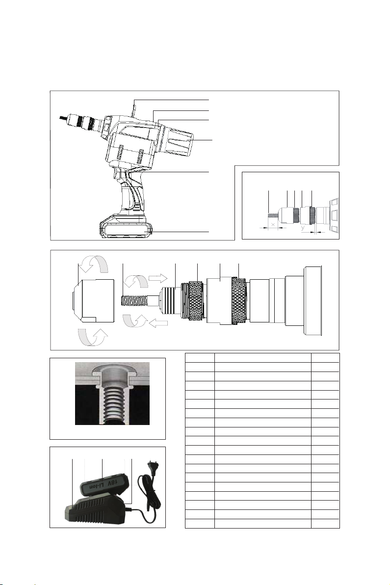
2.7.1 Setting the threaded mandrel length x (Fig. 2)
● Set the threaded mandrel length x to the blind rivet nut length by
turning the nosepiece B.
● Fully utilise the thread depth of closed blind rivet nuts (Fig. 2; 4).
● Secure setting of nosepiece B with lock nut C.
2.7.2 Adjusting the setting stroke y (Fig. 2)
● The setting stroke y depends on the size of the blind rivet nut
(M3-M10) and of the rivetable material z (Fig. 4).
Reference values for setting stroke y:
● The setting stroke y is adjusted by screwing the setting nut D in and out.
● Initially adjust the setting stroke y to the “min.” value and then set a blind
rivet nut.
● If the blind rivet nut does not form a distinct closing as shown in Fig. 4 ,
increase the setting stroke y in steps.
● Secure the setting nut D with lock nut E.
Caution!
The following safety rules must be observed to ensure adequate protection
against electric shock, injuries or fire hazards
WARNING:
ALWAYS WEAR SAFETY GLASSES WHEN OPERATING
AND PERFORMING MAINTENANCE ON TOOL
LIMITED TOOL WARRANTY
HOWMET Fastening System, Marson Division, warrants that this tool will be free from defects in material and workmanship
under normal service for ninety (90) days from the date of purchase. This warranty applies to the purchaser of the tool for original
use only. All other warranties, whether expressed or implied, including any warranties of merchantability or fitness for purpose are
hereby excluded.
Should this tool fail during this ninety (90) day period, and no unauthorized repairs have been made, return the tool freight prepaid
to the factory for free of charge replacement of any part or parts found by HOWMET Fastening System, Marson Division, to be
defective due to faulty material or workmanship. This represents the sole obligation of HOWMET Fastening System, Marson
Division, under this warranty. In no event shall Howmet Fastening System, Marson Division, be liable for any consequential or
special damages arising from the purchase or use of this tool. You may have other rights, which vary from state to state.
LIMITED TOOL WARRANTY
HOWMET Fastening System, Marson Division, warrants that this tool will be free from
defects in material and workmanship under normal service for ninety (90) days from the date
of purchase. This warranty applies to the purchaser of the tool for original use only. All other
warranties, whether expressed or implied, including any warranties of merchantability or
fitness for purpose are hereby excluded.
Should this tool fail during this ninety (90) day period, and no unauthorized repairs have been
made, return the tool freight prepaid to the factory for free of charge replacement of any part
or parts found by HOWMET Fastening System, Marson Division, to be defective due to faulty
material or workmanship. This represents the sole obligation of HOWMET Fastening System,
Marson Division, under this warranty. In no event shall Howmet Fastening System, Marson
Division, be liable for any consequential or special damages arising from the purchase or use
of this tool. You may have other rights, which vary from state to state.