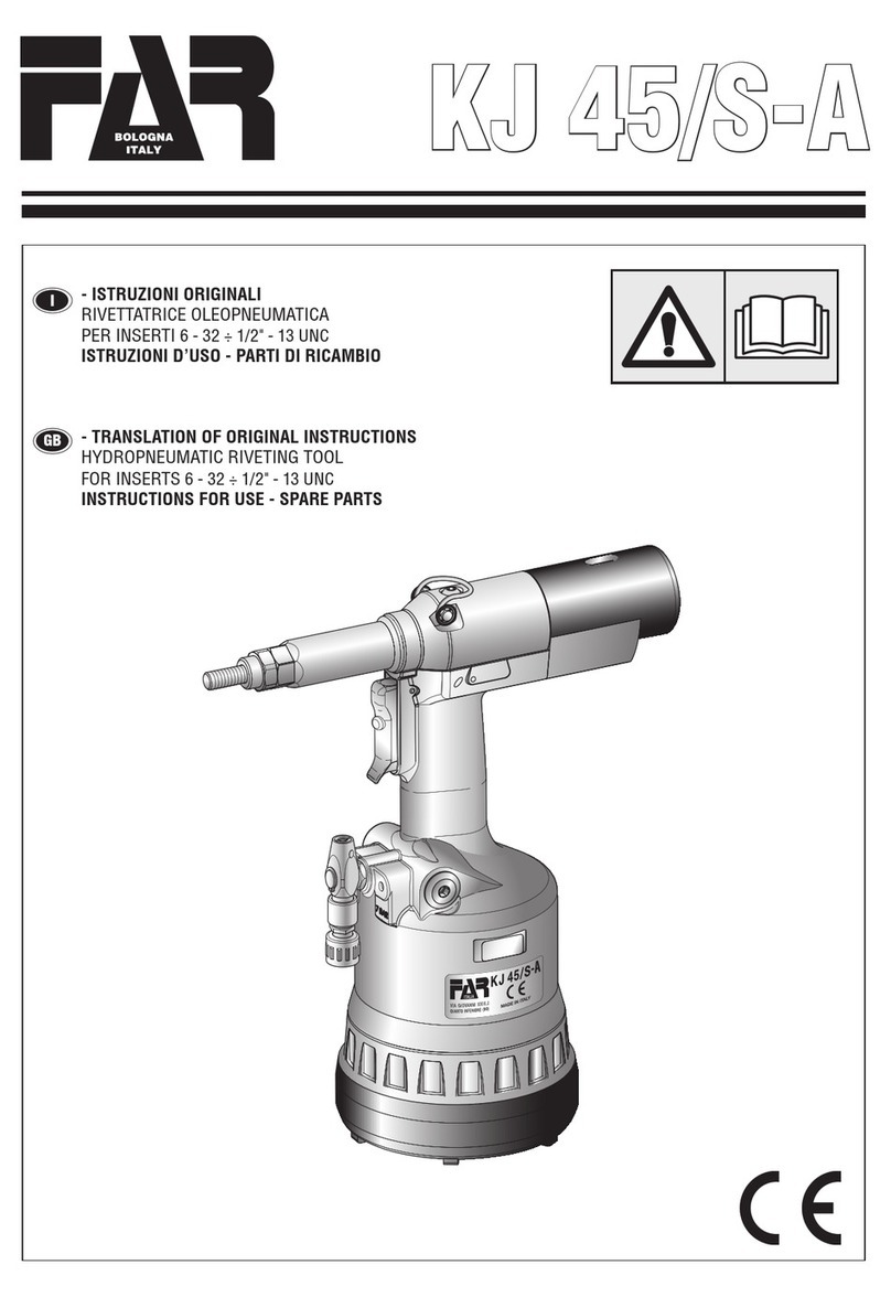
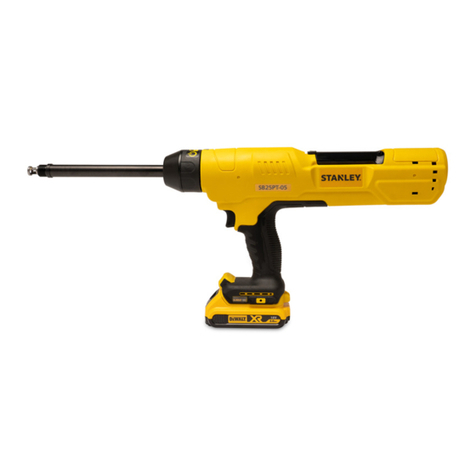
FAR KJ 45/S Setup guide

KJ 45/S
I
GB
F
E
D
- ISTRUZIONI ORIGINALI
RIVETTATRICE OLEOPNEUMATICA
PER INSERTI M4/M12
ISTRUZIONI D’USO - PARTI DI RICAMBIO
- TRANSLATION OF ORIGINAL INSTRUCTIONS
HYDROPNEUMATIC TOOL
FOR INSERTS M4/M12
INSTRUCTIONS FOR USE - SPARE PARTS
- TRADUCTION DES INSTRUCTIONS ORIGINALES
OUTIL À RIVETER OLÉOPNEUMATIQUE POUR
ÉCROUS À SERTIR M4/M12
MODE D’EMPLOI - PIECES DETACHEES
- ÜBERSETZUNG VON ORIGINALANLEITUNGEN
PNEUMATISCH-HYDRAULISCHES NIETWERKZEUG
FÜR BLINDNIETMUTTERN M4/M12
BEDIENUNGSANLEITUNG - ERSATZTEILE
- TRADUCCION DE LAS ISTRUCCIONES ORIGINALES
REMACHADORA OLEONEUMATICA
PARA TUERCAS M4/M12
INSTRUCCIONES DE USO - PIEZAS DE REPUESTO
- TŁUMACZENIE ORYGINALNEJ INSTRUKCJI
NITOWNICA OLEO-PNEUMATYCZNA
DO NITONAKRĘTEK M4/M12
INSTRUKCJA OBSŁUGI - CZĘŚCI ZAMIENNE
- ПЕРЕВОД ОРИГИНАЛЬНЫХ ИНСТРУКЦИЙ
МАСЛЯНО – ПНЕВМАТИЧЕСКИЙ ЗАКЛЁПЫВАЮЩИЙ АППАРАТ
ДЛЯ ВСТАВОК М4/М12
ИНСТРУКЦИИ ПО ИСПОЛЬЗОВАНИЮ - ДЕТАЛИ
PL
RUS

GB
12 Date 07-2016 Revisione - 08
KJ 45/S
INSTRUCTIONS FOR USE I
INDEX
GUARANTEE ............................................................................. 12
SAFETY MEASURES AND REQUIREMENTS ............................. 12
TOOL IDENTIFICATION ............................................................. 13
GENERAL NOTES AND USE...................................................... 13
MAIN COMPONENTS................................................................ 13
TECHNICAL DATA ..................................................................... 13
AIR FEED................................................................................... 14
PRELIMINARY OPERATIONS.................................................... 14
PLACING OF THE INSERT......................................................... 15
WORKING PROBLEMS ............................................................. 16
CHANGE OF SIZE ..................................................................... 17
ADJUSTMENT OF TIE-ROD/HEAD UNIT................................... 18
TOOPING UP THE OIL-DYNAMIC CIRCUIT............................... 19
MAINTENANCE ........................................................................ 19
DISPOSAL OF THE RIVETING TOOL ......................................... 19
CAUTION!!!
All the operations must be done in conformity
with the safety requirements, in order to avoid
any consequence for your and other people
security and to allow the best tool work way.
• Read the instructions carefully before using the tool.
• For all maintenance and/or repairs please contact FAR s.r.l.
authorized service centers and use only original spare parts.
FAR s.r.l. may not be held liable for damages from defective parts
caused by failure to observe what mentioned above (EEC directive
85/374).
The list of the service centres is available on our website
http://www.far.bo.it ( Organization )
• The tool must be used only by expert workers.
• A protective visor and gloves must be put on when using the
tool.
• Use equipment recommended in the maintenance chapter to do
any maintenance and/or regulation of the tool.
• For topping up the oil, we suggest using only fluids in accordance
with the features specified in this working book.
• If any drop of oil touches your skin, you must wash with water
and alkaline soap.
ATTENTION! In case of strong impacts or accidental
falls the machine should be completely overhauled.
GUARANTEE
FAR riveting tools are covered by a 12-month warranty. The
tool warranty period starts on the date of delivery to the
buyer, as specified in the relevant document. The warranty
covers the user/buyer provided that the tool is purchased
through an authorized dealer and only if it is used for the
purposes for which it was conceived. The warranty shall
not be valid if the tool is not used or maintained as specified
in the instruction and maintenance handbook. In the event
of defects or failures, FAR S.r.l. shall undertake solely to
repair and/or replace the components it judges to be faulty.
SAFETY MEASURES AND REQUIREMENTS
• The tool can be carried and we suggest putting it into its box after
using.
• The tool needs a thorough six-monthly overhaul.
• Repairing and cleaning operations must be done when the tool
is not fed.
• A safety balancer is suggested when it is possible.
• If the A-weighted emission sound pressure level is more than
70 dB (A), you must use some hearing protections (anti-noise
headset, etc.).
• The workbench and the work surface must be always clean and
tidy. The untidy can cause damages to people.
• Do not allow unauthorized persons to use the working tools.
• Make you sure that the compressed air feeding hoses have the
correct size to be used.
• Do not carry the connected tool by pulling the hose. The hole
must be far from any heating sources or from cutting parts.
• Keep the tools in good conditions; do not remove either safety
parts or silencers.
• After repairing and/or adjusting, make sure you have already
removed the adjusting spanners.
• Before disconnecting the compressed air hose from the tool
make sure that there is no pressure in the hose.
• These instructions must be carefully followed.

13
GB
Revisione - 08 Date 07-2016
KJ 45/S
TOOL IDENTIFICATION
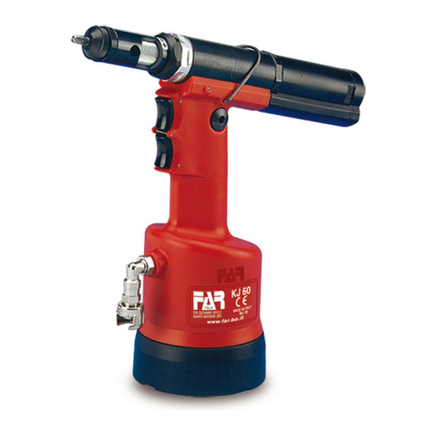
The riveting tool KJ 45/S is identified from a marking
that shows company name and address of manufacturer,
designation of the tool, CE. Always refer to the information on
the riveting tool when requesting technical service.
GENERAL NOTES AND USE
The tool can be employed only for blind rivet nuts M4÷M12.
TheKJ45/S/Shydropneumatic systemassuresmorepower
thanthepneumaticsystemusedforothermodels.Thatmeans
a reduction in the problems due to the wear and tear of the
components,therefore, therewill bean increaseinreliability.
The technical solutions adopted reduce the dimensions and
the weight of the tool, which is very handy for these reasons.
The possibilities ofleakagefromthe oil-dynamic system, are
eliminatedby some sealedgaskets,whichsolvethisproblem.
TECHNICAL DATA
• Working pressure ....................................................... 6 - 7 BAR
• Min. int. diam. of the compressed air
feeding hose..................................................................... 8 mm
• Max free air consumption per cycle................................ 9 Nl**
• Maximum force ......................................... 6,5 BAR - 27440 N
• Weight (with equipment for M10)................................2,860 Kg
• Working temperature................................................... -5°/+50°
• Root mean square in total acceleration
frequency (Ac) to which
the arms are subjected ............................................. < 2.5 m/s2
** nl = litres at 20°, pressure of 1 atmosphere
• A-weighted emission sound pressure level ................... 74 dBA
• Peak C-weighted instantaneous sound pressure .......<130 dBC
• A-weighted emission sound pressure ........................... 86 dBA
*with M10 tie rod
MAIN COMPONENTS
A).........................................................................Threaded tie rod
B).......................................................................................... Head
C).............................................................Ring-nut clamping head
D)...................................................................Control push-button
E) ....................................................... Compressed air connection
F) ............................................................... Pressure control valve
G)......................................................................Protection bottom
H)....................................................................... Pneumatic motor
I)................................................................................Oil tank plug
L) ...................................................................Balancer connection
M)...............................................................Stroke-adjusting knob
N)......................................................................... Stroke indicator
O).................................................................... Tube carrying head
P).....................................................................Unscrewing button
Q)...................................................................... Air-entry valve
Company name and
address Designation of the tool
Serial number

GB
14 Date 07-2016 Revisione - 08
KJ 45/S
AIR FEED (fig. f1)
The compressed air system must be provided with air
cleaners and condensation drains and must guarantee that
the air supplied to the feeder has a constant pressure of min
6 bars. The regulator must be set at a pressure of 6,5 bars.
Connect the machine to the main compressed air supply as
shown in the diagram (f1):
1)Cutoff cock (used during maintenance of the filter regulator
or of the lubricating unit).
2)Main supply inlet.
3)Main supply bleed.
4)Pressure regulator and filter (bleed daily).
5)Lubricating unit.
ATTENTION! The riveting tool is equipped with a
relief valve (F) starting when the compressed-air
pressure significantly exceeds 7 bar.
ATTENTION! If the relief valve (F) starts and the air
consequently escapes, we recommend to check if
the tool feed pressure corresponds to the pressure
value indicated under the technical data in this
handbook (page 13).
FRL UNIT
PRELIMINARY OPERATIONS (fig. f2-f3)
Check that the threaded tie rod (A) and head (B) couple
assembled on the riveting tool is suitable to the size of the
insert to clamp; otherwise change the size (page 17). The
tie-rod (A)/head (B) unit assembled on this riveting tool,
corresponds to a M10 thread.
Beforeusingtherivetingtoolandaftereachchangeofsize,the
stroke should be adjusted according to the dimensions, type
of the insert and thickness of the material to clamp. Before
carrying out this operation rotate the knob (M) according
to the direction of the arrow, (+) for increasing the stroke
and (-) for decreasing it. Increasing the stroke - rotation of
knob (M) - in the direction indicated with the symbol (+), the
distance “h” (page 15) decreases increasing the clamping
action.Toverify thatthestrokeiscorrectlyadjustedcheck the
indicator(N)comparingit with the valuesofthetable (fig.f3).
NOTE: Before the definitive placingofthe insert, its clamping
on the thicknesses involved should be checked, carrying
out other adjustments, as shown at page 18 (the specified
adjustments are just an indication, it is advisable to see the
technical data of the inserts used).
ATTENTION! The incorrect adjustment of the
riveting tool can cause a bad clamping of the
inserts and a possible break of the tie rod!
ATTENTION! The above-mentioned operations
must be done when the tool is not fed. For
visualizing the changed stroke (N) the tool
must be fed.
f2
1
2
4
53
3 m Max
f1
F
Q
• Move up the slider of the air-entry valve (Q) to feed the tool.
• Beforeregulatingthestroke,dischargethetoolbytheairandstop
the feeding, moving down the slider of the air-entry valve (Q).

15
GB
Revisione - 08 Date 07-2016
KJ 45/S
f3
Tie rod min. stroke Revolutions (M)
~ 2 mm 0
Tie rod stroke Revolutions (M)
~ 0.4 mm 1
Tie rod max. stroke Revolutions (M)
~ 8 mm 15
0
1
2
3
4
5
6
7
98
10
11
12
13
14
15
M12 1 ÷ 4
M
4
0
.
3
÷
4
M
5
0
.
5
÷
5
M
8
0
.
8
÷
6
M
1
0
1
÷
6
M
1
2
1
÷
7
/
M
6
0
.
5
÷
6
PLACING OF THE INSERT (fig. f4-f5-f6)
Check that the threaded tie rod (A) and head (B) couple
assembled on the riveting tool is suitable to the size of the
insert to be used.
Adjust the stroke as indicated (fig. f2-f3).
Introduce the insert on the tie rod (A) and push slightly on it
as indicated in figure f4, so as to make it clamp automatically
onthethreadedtierod.Makesurethattheinsertheadtouches
the head (B) checking that the tie rod (A) comes out of 2mm
from the insert.
In case of further adjustments of the tie rod (A) follow the
instructions of page 18.
It is now possible to place the insert pushing the button (D)
(fig.f5) until the insert is completely pulled, and push the
button (P) to release the tie rod (fig.f7).
For a correct placing and right working of the machine, the
inserts to be used should be properly cleaned.
Note: According to the desired clamping, carry out other
adjustments of the riveting tool stroke, rotating the knob
(M) (fig. f2-f3-f6), if necessary.
Insufficient deformation = the insert could rotate inside the
housing compromising its use and resistance.
Excessive deformation = possible damages of the insert
and tie rod (A) with eventual breaks of both components.
D
M
f5
f4
f6
BA

GB
16 Date 07-2016 Revisione - 08
KJ 45/S
WORKING PROBLEMS (fig. f7)
Any time it is necessary to unscrew forcedly the threaded
tie rod from the insert, push the button (P).
ATTENTION! Carry out this operation keeping
the riveting tool firmly in order to avoid sharp
movements which could damage people or
things.
f7

17
GB
Revisione - 08 Date 07-2016
KJ 45/S
ATTENTION!
Disconnect the machine before carrying out the
above-mentioned operations.
CHANGE OF SIZE (fig. f8-f9-f10-f11)
The riveting tool is supplied with 6 pairs of threaded tie-rods
(A), heads (B), entreiners (R) and, spacers (S) only for tie-
rods from M4 to M6 (f8).
To change the size make as follows:
• Unscrewthe cone-carryinghead (O)bya22mmstandard
spanner (f9).
• Extract the threaded tie-rod, pushing and lifting it at the
same time (f10).
• After preparing the threaded tie-rod (A) of the size you
need, arrange and keep the components as shown in f11
and assemble. Be sure that the components are correctly
placed, rotating the tie-rod by hand (f11).
ATTENTION!
• The side of the component (R) to be entered in the head
of the tie-rod is provided of a magnet to avoid accidental
fall during the operations of change of size.
• Screw the cone carrying heads (O) by a 22 mm standard
spanner and clamp correctly.
M8 - M12M4 ÷ M6
A RB A RBS
f8
22 mm
O
f11
f10
f9

GB
18 Date 07-2016 Revisione - 08
KJ 45/S
TIE-ROD/HEAD UNIT ADJUSTMENT (fig. f14-f15-f16)
Changing the length of the insert to clamp, the position of
the head (B) compared to the threaded tie rod (A) should
be adjusted.
Disconnect the compressed air feeding from the tool.
Screw an insert of the desired length on the threaded tie
rod manually until the insert head touches the riveting tool
head (B). The head is adjusted correctly if the threaded tie
rod comes out of the insert screwed on it of about 2 mm.
Otherwise unblock the ring nut (C) with a 22 mm standard
spanner then screw or unscrew the head (B) up to the right
position, and block the ring nut (C).
ATTENTION!
Disconnect the machine before carrying out the
above-mentioned operations.
A
BC
B
f15
f16
f14
22 mm
C

19
GB
Revisione - 08 Date 07-2016
KJ 45/S
TOPPING UP THE OIL-DYNAMIC CIRCUIT (fig. f17-f18)
Theoil-dynamiccircuitshouldbetoppedupafteralongperiod
of work or when there is a power loss of the riveting tool.
Put the riveting tool (not fed) in a vertical position rotating
the knob (M) towards the sign “+” up to the end of stroke,
and remove the plug (I) by means of a 4 mm Allen wrench
(equipped). During this operation check the oil level in order
to avoid any overflowing. Then pour the oil HLP 32 cSt into
the oil container (T) (equipped) which shall be screwed to
its seat on the plug (I).
Whilekeepingtherivetingtoolinverticalpositionandstarting
air feeding, push the button (D) and make the riveting tool
carry out some cycles until air bubbles inside the container
stop coming out. This condition indicates that the topping
up of the oil has been fully achieved. At this point stop the
air feeding and while keeping the riveting tool in a vertical
position, unscrew and close the oil container (T) and the
plug (I) checking the soundness of the hermetic washer and
repeat all the adjustments for placing the insert as indicated
at page 14-15.
ATTENTION: It is very important to follow the above-
mentioned instructions and use gloves during oil topping up.
If you need to empty completely the hydraulic circuit, you
must put the oilin a suitable containerandcontactacompany
authorized to dispose of wastes.
MAINTENANCE
Daily maintenance
- Check that the threaded tie rod is not damaged.
- Check the supply system of the compressed air.
- Check that the stroke of the tool is suitable for the selected
inserttoclamp(seethepertaininginstructionsforadjusting
the stroke, indicated at page 14).
- Check that there are neither air nor oil leakages. In this
case replace possible damaged connectors or seals.
- Checkthatthe supplypressure of thecompressedairdoes
not exceed 7 bar.
Weekly maintenance
- Checkthe oillevel controllingthe strokeoftherivetingtool.
If necessary fill up for preventing failures of the riveting
tool as indicated (fig. f18).
Overhaul of the riveting tool
It is advisable to carry out a complete overhaul of the riveting
tool after 600,000 cycles or every year.
In this case apply only to centres authorized by FAR S.r.l.
DISPOSAL OF THE RIVETING TOOL
Follow the prescriptions of the national laws for
disposing of the riveting tool.
After disconnecting the tool from the pneumatic
system,disassemble and split allthe components
accordingtothematerial:steel,aluminium, plastic
material, etc.
Then proceedtoscrapthematerialsin accordance
with current laws.
ATTENTION!
Before disconnecting the compressed air hose,
make sure that it is not under pressure!
ATTENTION: Make sure that the oil filler cap ( I )
is tightened at a torque corresponding to Min. 5
Nm ÷ Max. 8 Nm.
We recommend to use oil HLP 32 cSt or similars.
f17
f18

Date 07-2016 Revisione - 08
GB
62
KJ 45/S
SPARE PARTS
Tab. 1/5
No. CODE Q.ty DESCRIPTION
001 713291 1 Head M 10
002 71C00281 1 Screw TCCE M10 x 70 UNI 5931 - 12,9
003 72A00105 1 Hexagonal unit for tie-rod M 10
004 713292 1 Head M 12
005 713177 1 Tie rod M 12
006 72A00104 2 Hexagonal unit for tie-rod M 8÷M 12
007 713290 1 Head M8
008 71345529 1 Spacer for screw M 8
009 71C00514 1 Screw TCCE M8 x 70 UNI 5931 - 12,9
010 713289 1 Head M 6
011 71345276 1 Spacer for screw M 6
012 71C00279 1 Screw TCCE M6 x 70 UNI 5931 - 12,9
013 72A00103 1 Hexagonal unit for tie-rod M 6
014 713288 1 Head M 5
015 71345275 1 Spacer for screw M 5
016 71C00278 1 Screw TCCE M5 x 70 UNI 5931 - 12,9
017 72A00102 1 Hexagonal unit for tie-rod M 5
018 713287 1 Head M 4
019 71345274 1 Spacer for screw M 4
020 71C00277 1 Screw TCCE M4 x 65 UNI 5931 - 12,9
021 72A00101 1 Hexagonal unit for tie-rod M 4
022 709033 1 Plastic case
023 75036018 1 Instructions for use
024 72A00053 1 Oil container
025 712225 1 Wrench 4 mm
107 71345831 1 Tie rod M8
KIT
KITA 74000042 Pneumatic Kit
030A 71C00295 1 Ring Parbak 8-028
031A 71C00296 1 Gasket OR 5-670
032A 710925 1 Gasket OR 027
035A 711062 1 Gasket OR 2-126
037A 710244 1 Gasket OR 2-130
038A 713275 1 Gasket OR 2-122
056A 713390 2 Gasket OR 2-007
058A 710258 1 Gasket OR 5-612
059A 710921 1 Gasket OR 2-115
060A 71C00529 1 Gasket XR 008 PP180 B.
061A 710528 1 Gasket OR 008
062A 710572 1 Gasket OR 2-120
063A 710385 2 Gasket OR 2-006
064A 713394 1 Gasket OR 2-106
066A 710376 2 Gasket OR 2-009
068AHI 711338 2 Gasket OR 2-003
069AHI 710918 2 Gasket OR 2-005
070AHI 716060 5 Gasket OR 2-010
075A 713400 7 Gasket OR 5-616
077A 71C00355 1 Gasket OR 1,78 x 8,73
078A 71C00356 1 Gasket OR 1,78 x 7,66
082A 71C00522 1 Gasket OR 5-615
083A 710914 1 Gasket OR 2-116
100A 71C00297 2 Gasket OR 6-700
101A 713398 1 Gasket OR 2-340
102A 710350 1 Gasket OR 2-109
105AP 713192 5 Cage
106A 713271 2 Gasket OR 2-014
KITB 74000027 Tie rod container kit
KITQ 74000037 Oil-dynamic kit
026Q 711722 1 Gasket B-094063/B/NEI
034Q 713389 1 Gasket 157118 - B / NEO
080Q 711827 1 Gasket TTS-12-19-5,7 / L
081Q 710390 1 Gasket B-075047
KIT It indicates that the part is sold in kits consisting of
different parts in different quantities.
Tab. 2/5
No. CODE Q.ty DESCRIPTION KIT
026Q 711722 1 Gasket B-094063/B/NEI Q
027 713402 1 Seeger ring JV 25
028 71345258 1 Jacket
029 71345261 1 Flange
030A 71C00295 1 Ring Parbak 8-028 A
031A 71C00296 1 Gasket OR 5-670 A
032A 710925 1 Gasket OR 027 A
033 71345264 1 Oil-dynamic piston
034Q 713389 1 Gasket 157118 - B / NEO Q
035A 711062 1 Gasket OR 2-126 A
036 71345260 1 Ring nut
037A 710244 1 Gasket OR 2-130 A
038A 713275 1 Gasket OR 2-122 A
039 72A00125 1 Pneumatic Motor F001
040 72A00188 1 Valve unit for motor control
041 71345263 1 Nut M 16 x 1
042 72A00107 1 Driving unit
043 71345516 1 Spring for tie-rod
044 71345515 1 Sleeve carrying tie rod
046 71345517 1 Sleeve
047 713170 6 Ring nut
048 716198 1 Screw TCCE M4 x 12 UNI 5931
049 72A00009 1 Fender motor
050 710555 1 Washer 400-004-4490
051 713405 1 Screw TBCE M6 x 10 ISO 7380
053 713308 2 Cap
054 713406 2 Screw TSCE M4 x 25 UNI 5933
055 72A00007 1 Air connector
056A 713390 2 Gasket OR 2-007 A
057 716150 2 Screw TSCE M4 x 12 UNI 5933
058A 710258 1 Gasket OR 5-612 A
059A 710921 1 Gasket OR 2-115 A
060A 71C00529 1 Gasket XR 008 PP180 B. A
110G 713158 1 Obturator G
111G 71345174 1 Right spear valve G
KIT
KITC 74000041 Oil-dynamic cylinder kit
KITD 74000025 Hook kit
KITE 74000021 Silencer kit
KITF 74000029 Rod kit
KITG 74000073
Spear valve group
110G 713158 1 Obturator
111G 71345174 1 Right spear valve
KIT It indicates that the part is sold in kits consisting of
different parts in different quantities.

Revisione - 08 Date 07-2016
GB
63
KJ 45/S
SPARE PARTS
Tab. 3/5
No. CODE Q.ty DESCRIPTION KIT
061A 710528 1 Gasket OR 008 A
062A 710572 1 Gasket OR 2-120 A
063A 710385 2 Gasket OR 2-006 A
064A 713394 1 Gasket OR 2-106 A
065 713401 1 Pin NRB ø 3 x 19.8
066A 710376 2 Gasket OR 2-009 A
067 72A00019 1 Push-button unit
068AHI 711338 2 Gasket OR 2-003 AHI
069AHI 710918 2 Gasket OR 2-005 AHI
070AHI 716060 4 Gasket OR 2-010 AHI
108 71345648 1 Push-button
109 71345649 1 Unscrewing button
KIT
KITH 74000033 Upper piston kit
KITI 74000034 Lower piston kit
KITL 74000035 Retaining plate kit
KITM 74000053 Handgrip kit
KIT It indicates that the part is sold in kits consisting of
different parts in different quantities.
Tab. 4/5
No. CODE Q.ty DESCRIPTION KIT
070AHI 716060 1 Gasket OR 2-010 AHI
071 72C00017 1 Body
072 713403 1 Ball ø 5,5
073 71345272 1 Valve cap
074 71345273 1 Coil
075A 713400 7 Gasket OR 5-616 A
076 72A00028 1 Air connector unit 1/4"
077A 71C00355 1 Gasket OR 1,78 x 8,73 A
078A 71C00356 1 Gasket OR 1,78 x 7,66 A
079 713304 1 Guide steam connector
080Q 711827 1 Gasket TTS-12-19-5,7 / L Q
081Q 710390 1 Gasket B-075047 Q
082A 71C00522 1 Gasket OR 5-615 A
083A 710914 1 Gasket OR 2-116 A
084 713319 1 Nut M 22 x 1,25
085 713320 1 Connector
086 713315 1 Steam
087 713197 1 Body cover
088 713194 1 Knob
089 713316 1 Ring nut
090 713191 1 Disc
091 712575 1 Screw TSCE M5 x 12 UNI 5933
092 713404 4 Tapping screw TSP ø 2,5 x 12
093 713317 1 Flanged connector
094 713318 1 Driving shaft
095 713321 1 Double-thread screw
096 713322 1 Screw M 5
097 713199 1 Push-button spring
098 713196 1 Protection bottom
099 713434 1 Seeger ring 11 UNI 7435
100A 71C00297 2 Gasket OR 6-700 A
101A 713398 1 Gasket OR 2-340 A
102A 710350 1 Gasket OR 2-109 A
103 72B00021 1 Overpressure valve unit
Tab. 4/5
No. CODE Q.ty DESCRIPTION KIT
104 71C00305 1 Ring nut 1/4"
105AP 713192 5 Cage AP
106A 713271 2 Gasket OR 2-014 A
112 713306
1
Tube ø 8 x 7
KIT
KITN 74000030 Pneumatic piston kit
KITO 74000031 Pneumatic jacket kit
KITP 74000023 Coil kit
KIT It indicates that the part is sold in kits consisting of
different parts in different quantities.
Tab. 5/5
No. CODE Q.ty DESCRIPTION
001 71C00764 1 Bearing 61801
002 71345645 1 Gear cage
003 71345644 3 Planetary gear
004 71345643 1 Crown gear
005 71345642 1 Washer
006 71C00763 1 Bearing AY7-ZZ
007 71345640 1 Connector
008 71C00761 2 Spring pin ø 1,5 x 10 UNI 6875
009 71345639 5 Vane
010 71345638 1 Rotor
011 71345637 1 Outside body
012 71345641 1 Back cap
013 713037 1 Pin ø 2 X 9,8
014 71C00762 1 Bearing 695-ZZ
A 72A00125 Pneumatic Motor F001
Other manuals for KJ 45/S
3
Table of contents
Other FAR Rivet Tools manuals
Popular Rivet Tools manuals by other brands

Mighty Seven
Mighty Seven PB-1310 manual

Degometal
Degometal GO 210 TRANSLATION OF ORIGINAL INSTRUCTIONS

HS-Technik
HS-Technik NutBee NBLS-21 operating instructions

Sumake
Sumake ST-6615 manual

Howmet Aerospace
Howmet Aerospace Marson BT-5 instruction manual

Westfalia
Westfalia 86 05 73 Original instruction manual