I
II
III
I
II
III
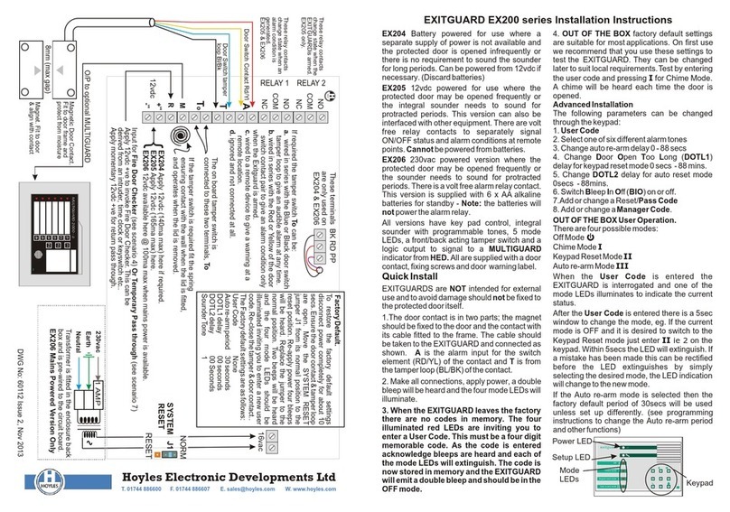
Chime mode Chime mode
Off Off
Keypad reset mode Keypad reset mode
Auto re-arm mode Auto re-arm mode
1 1
4 45 56 6
7 78 80 0
2 2
3 3
IIIIIIII IIIIIIIIII IIIIII
exitguard exitguard
Keypad Keypad
Mode LEDs Mode LEDs
Power LED Power LED
Setup LED Setup LED
EXITGUARD User Instructions EXITGUARD User Instructions
These user instructions apply to EX204, EX205 and EX206 to make a note of this new number or your installation
versions of the EXITGUARD. For details on setting various company maymake acharge to reset theEXITGUARD.
functions refer to Installation Instruction 60086. available on WARNING! Do NOT use maintenance mode unless you
our website www.hoyles.com. have the installation instructions available. See our website
When your EXITGUARD has been installed and set up you www.hoyles.com. If you accidentally enter thismode key O
will have been given a 4 digit USER CODE. Make a note of to leave it.The EXITGUARD willbe in theOFF mode.
the number in the box above, you will need this number to Battery Monitor
switch to any of the various modes or to silence the The EX204 EXITGUARD can be powered from 6 x AA
EXITGUARD if it is sounding. alkaline batteries. These can last up to 5 years. Before the
There are four possible user modes batteries become exhausted the EXITGUARD will emit
periodic warning bleeps and the maintenance LED will
1.OFF.The protected door can be opened without sounding flash. On interrogating with the User Code the relevant
the alarm. mode LED will illuminate also with the LED to warn of
2.CHIME. When a door opens the EXITGUARD will sound impending battery failure. The batteries can be changed
a short chime, like a shop door bell. without losing the user code or set up parameters.
3.KEYPAD RESET. When the door opens the Anti Tamper Protection
EXITGUARD sounds until the user code is entered. All EXITGUARDs are fitted with tamper detection. This is
4.AUTO RE-ARM. When the door opens the EXITGUARD indicated bya lowpitch barpand LED
sounds and resets a short time after the door is closed (This Fire Door Checker.
time delayis usuallyset to seconds If your EXITGUARD is being used for Fire Door Verification
You can interrogate the mode status at any time: Simply you will need to open and close each protected door when
type in the User Code, one of the 4 Mode LED will illuminate the LEDs strobe with a periodic bleep. This may be after
for a period of 5 seconds. entering the building or at a set time determined by a time
1. To use Chime Mode enter the USER CODE to clock. Note: Keypad is locked until verification is complete.
interrogate the EXITGUARD and enter 1 before any mode NOT installed.
LEDs extinguish. The Chime LED illuminates for about 5 Installed to operate on entering the building.
seconds. When it extinguishes the EXITGUARD is set to
Chime Mode. Installed tooperate at am/pm on
2. To use Keypad Reset Mode enter the USER CODE to Mon Tue Wed Thu Fri Sat Sun
interrogate the EXITGUARD and enter 2 before any mode Door Open Too Long (DOTL) delay
LEDs extinguish. The Code Reset LED illuminates for Your EXITGUARD may have been set up to incorporate a
about 5 seconds. When it extinguishes the EXITGUARD is delay before sounding, usually for fire doors that are in
set to Code Reset Mode. regular use where it would be inconvenient to switch off
3. To use Auto Re-arm Mode enter the USER CODE to each time a door is opened for a short period. This is best
interrogate the EXITGUARD and enter 3 before any mode used in the Auto Re-arm mode.
LEDs extinguish. The Auto Re-arm LED illuminates for This feature is NOT installed
about 5 seconds. When it extinguishes the EXITGUARD is
This featureis installed.The delayis setto secs.
set to Auto Re-arm Mode.
Bleep When OFF
4. To switch to the OFF mode enter the USER CODE to
interrogate the EXITGUARD and enter O before any mode Your EXITGUARD may have been set up to bleep
LEDs extinguish. The Off LED illuminates for about 5 periodically when in the OFF mode. This helps prevent
seconds to indicate that the EXITGUARD is switched OFF. doors being left un-protected.
If you need to change the user code proceed as follows: This feature is installed.
a. Enter the existing user code to interrogate the This feature is NOT installed
EXITGUARD
b. Enter 7 before any mode LEDs extinguish. This is a Your installation engineer should complete the boxes
maintenance mode,the LEDwill illuminate. above and leave these instructions with you.
c. Enter 1, a double bleep is heard and the four mode LEDs Engineer: Date:
illuminate inviting you to enter a new four digit user code.
Installation Co.
d. As each digit is entered a mode LED will extinguish.
e. When the code is complete a double bleep is heard. The Telephone Number:
unit is now ready for use but in the OFF mode. Don’t forget
These user instructions apply to EX204, EX205 and EX206 to make a note of this new number or your installation
versions of the EXITGUARD. For details on setting various company maymake a charge toreset the EXITGUARD.
functions refer to Installation Instruction 60086. available on WARNING! Do NOT use maintenance mode unless you
our website www.hoyles.com. have the installation instructions available. See our website
When your EXITGUARD has been installed and set up you www.hoyles.com. If you accidentally enter thismode key O
will have been given a 4 digit USER CODE. Make a note of to leave it.The EXITGUARD willbe in theOFF mode.
the number in the box above, you will need this number to Battery Monitor
switch to any of the various modes or to silence the The EX204 EXITGUARD can be powered from 6 x AA
EXITGUARD if it is sounding. alkaline batteries. These can last up to 5 years. Before the
There are four possible user modes batteries become exhausted the EXITGUARD will emit
periodic warning bleeps and the maintenance LED will
1.OFF.The protected door can be opened without sounding flash. On interrogating with the User Code the relevant
the alarm. mode LED will illuminate also with the LED to warn of
2.CHIME. When a door opens the EXITGUARD will sound impending battery failure. The batteries can be changed
a short chime, like a shop door bell. without losing the user code or set up parameters.
3.KEYPAD RESET. When the door opens the Anti Tamper Protection
EXITGUARD sounds until the user code is entered. All EXITGUARDs are fitted with tamper detection. This is
4.AUTO RE-ARM. When the door opens the EXITGUARD indicated bya lowpitch barpand LED
sounds and resets a short time after the door is closed (This Fire Door Checker.
time delayis usuallyset to seconds If your EXITGUARD is being used for Fire Door Verification
You can interrogate the mode status at any time: Simply you will need to open and close each protected door when
type in the User Code, one of the 4 Mode LED will illuminate the LEDs strobe with a periodic bleep. This may be after
for a period of 5 seconds. entering the building or at a set time determined by a time
1. To use Chime Mode enter the USER CODE to clock. Note: Keypad is locked until verification is complete.
interrogate the EXITGUARD and enter 1 before any mode NOT installed.
LEDs extinguish. The Chime LED illuminates for about 5 Installed to operate on entering the building.
seconds. When it extinguishes the EXITGUARD is set to
Chime Mode. Installed tooperate at am/pm on
2. To use Keypad Reset Mode enter the USER CODE to Mon Tue Wed Thu Fri Sat Sun
interrogate the EXITGUARD and enter 2 before any mode Door Open Too Long (DOTL) delay
LEDs extinguish. The Code Reset LED illuminates for Your EXITGUARD may have been set up to incorporate a
about 5 seconds. When it extinguishes the EXITGUARD is delay before sounding, usually for fire doors that are in
set to Code Reset Mode. regular use where it would be inconvenient to switch off
3. To use Auto Re-arm Mode enter the USER CODE to each time a door is opened for a short period. This is best
interrogate the EXITGUARD and enter 3 before any mode used in the Auto Re-arm mode.
LEDs extinguish. The Auto Re-arm LED illuminates for This feature is NOT installed
about 5 seconds. When it extinguishes the EXITGUARD is
This featureis installed.The delayis setto secs.
set to Auto Re-arm Mode.
Bleep When OFF
4. To switch to the OFF mode enter the USER CODE to
interrogate the EXITGUARD and enter O before any mode Your EXITGUARD may have been set up to bleep
LEDs extinguish. The Off LED illuminates for about 5 periodically when in the OFF mode. This helps prevent
seconds to indicate that the EXITGUARD is switched OFF. doors being left un-protected.
If you need to change the user code proceed as follows: This feature is installed.
a. Enter the existing user code to interrogate the This feature is NOT installed
EXITGUARD
b. Enter 7 before any mode LEDs extinguish. This is a Your installation engineer should complete the boxes
maintenance mode,the LEDwill illuminate. above and leave these instructions with you.
c. Enter 1, a double bleep is heard and the four mode LEDs Engineer: Date:
illuminate inviting you to enter a new four digit user code.
Installation Co.
d. As each digit is entered a mode LED will extinguish.
e. When the code is complete a double bleep is heard. The Telephone Number:
unit is now ready for use but in the OFF mode. Don’t forget
Note
If the EXITGUARD is sounding enter
the USER CODE
on the keypad to
silence it.
Five incorrect codes will result in keypad
lockout and barp for 10 seconds.
Power LED is only illuminated on EX205 and
EX206 when correctly powered.
Note
If the EXITGUARD is sounding enter
the USER CODE
on the keypad to
silence it.
Five incorrect codes will result in keypad
lockout and barp for 10 seconds.
Power LED is only illuminated on EX205 and
EX206 when correctly powered.
DWG No 60087 Issue 1 Aug 2004 DWG No 60087 Issue 1 Aug 2004
To be completed by installer
and left with customer. To be completed by installer
and left with customer.


