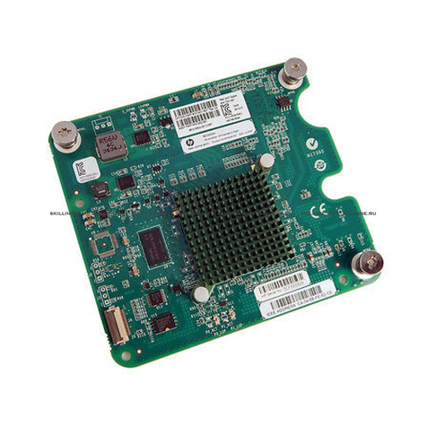
HP AH226A - Smart Array E500/256MB Controller... Installation instructions

HP 8 Internal Port SAS Controller and HP
Multi-Port Internal SAS Controller Support
Guide
HP-UX 11i v2, 11i v3
HP Part Number: 5900-0112
Published: September 2009
Edition: 6

©Copyright 2009 Hewlett-Packard Development Company L.P.
Legal Notices
The information contained herein is subject to change without notice. The only warranties for HP products and services are set forth in the express
warranty statements accompanying such products and services. Nothing herein should be construed as constituting an additional warranty. HP
shall not be liable for technical or editorial errors or omissions contained herein.
Intel, Pentium, Intel Inside, and the Intel Inside logo are trademarks or registered trademarks of Intel Corporation or its subsidiaries in the United
States and other countries.
Printed in Taiwan
Confidential computer software. Valid license from HP required for possession, use or copying. Consistent with FAR 12.211 and 12.212, Commercial
Computer Software, Computer Software Documentation, and Technical Data for Commercial Items are licensed to the U.S. Government under
vendor's standard commercial license.
The information contained herein is subject to change without notice. The only warranties for HP products and services are set forth in the express
warranty statements accompanying such products and services. Nothing herein should be construed as constituting an additional warranty. HP
shall not be liable for technical or editorial errors or omissions contained herein.
Trademark Notices UNIX is a registered trademark of The Open Group.

Table of Contents
Preface: About This Document .........................................................................................7
Intended Audience.................................................................................................................................7
New and Changed Documentation in This Edition...............................................................................7
Publishing History..................................................................................................................................7
What’s in This Document........................................................................................................................7
Related Documents.................................................................................................................................8
HP Encourages Your Comments............................................................................................................8
1 Controller Overview.......................................................................................................9
Serial-Attached SCSI (SAS) Technology Description.............................................................................9
Controller Description............................................................................................................................9
Connectors and Indicators...............................................................................................................11
2 Replacing a Controller.................................................................................................13
Replacement Overview.........................................................................................................................13
Preparing the Server.............................................................................................................................13
Replacing the Controller.......................................................................................................................13
Completing the Controller Replacement..............................................................................................14
3 Configuring the Controller Offline..............................................................................15
Integrated RAID....................................................................................................................................15
Integrated Mirror.............................................................................................................................15
Global Hot Spare.............................................................................................................................15
Configuration Utilities..........................................................................................................................15
The drvcfg Utility..................................................................................................................................16
Starting the drvcfg Utility................................................................................................................16
Using the drvcfg Utility With a Terminal Emulation Program.......................................................16
Configuration Utility Screens..........................................................................................................16
Adapter List Screen.........................................................................................................................16
Adapter Properties Screen...............................................................................................................17
RAID Properties Screens.................................................................................................................19
Select New Array Type Screen........................................................................................................20
Create New Array Screen................................................................................................................20
View A New Array Screen..............................................................................................................21
Manage A New Array Screen..........................................................................................................23
Manage Hot Spare......................................................................................................................23
Synchronize Array.....................................................................................................................23
Activate Array............................................................................................................................23
Delete Array...............................................................................................................................23
SAS Topology Screen.......................................................................................................................24
Device Properties Screen.................................................................................................................25
Device Format and Device Verify Screens.......................................................................................25
Formatting..................................................................................................................................26
Verifying.....................................................................................................................................26
Advanced Adapter Properties Screen.............................................................................................26
Advanced Device Properties Screen................................................................................................27
Spinup Properties Screen.................................................................................................................29
PHY Properties Screen.....................................................................................................................29
Table of Contents 3

Resetting the Error Counts.........................................................................................................31
Exiting drvcfg..................................................................................................................................31
Example: Adding, Viewing, and Deleting An Integrated Mirror Volume Using drvcfg.....................32
Determining the Driver ID and Ctrl ID...........................................................................................32
Adding An Integrated Mirror Volume............................................................................................33
Viewing the Properties of an Array.................................................................................................37
Deleting an Integrated Mirror Volume............................................................................................38
The cfggen Utility.................................................................................................................................41
Starting cfggen.................................................................................................................................41
Using cfggen....................................................................................................................................41
Rules for creating IM volumes and hot spare disks:.......................................................................42
The cfggen Command Set................................................................................................................42
Using the CREATE Command...................................................................................................42
Syntax ...................................................................................................................................42
Parameters.............................................................................................................................42
Operation..............................................................................................................................42
Using the AUTO Command.......................................................................................................43
Syntax....................................................................................................................................43
Parameters ............................................................................................................................43
Operation..............................................................................................................................43
HOTSPARE................................................................................................................................43
Syntax....................................................................................................................................43
Parameters ............................................................................................................................43
Operation..............................................................................................................................43
DELETE......................................................................................................................................43
Syntax....................................................................................................................................43
Parameters ............................................................................................................................44
Operation..............................................................................................................................44
DISPLAY.....................................................................................................................................44
Syntax....................................................................................................................................44
Parameters ............................................................................................................................44
Sample Output......................................................................................................................44
Logical drive status values: ..................................................................................................46
Physical device status values are as follows:........................................................................46
FORMAT....................................................................................................................................46
Syntax....................................................................................................................................46
Parameters ............................................................................................................................46
Operation..............................................................................................................................46
STATUS.......................................................................................................................................47
Syntax....................................................................................................................................47
Parameters ............................................................................................................................47
Operation..............................................................................................................................47
Sample Output......................................................................................................................47
ENABLEIR..................................................................................................................................47
Syntax....................................................................................................................................47
Parameters ............................................................................................................................47
Operation..............................................................................................................................47
DISABLEIR.................................................................................................................................48
Syntax....................................................................................................................................48
Parameters ............................................................................................................................48
Sample Output......................................................................................................................48
LOCATE.....................................................................................................................................48
Syntax....................................................................................................................................48
Parameters ............................................................................................................................48
Updating SAS Controller Firmware Offline.........................................................................................48
4 Table of Contents

4 Configuring and Troubleshooting the Controller Online.........................................51
Introduction..........................................................................................................................................51
Troubleshooting sasd............................................................................................................................51
The ioscan Utility.............................................................................................................................51
Displaying Interface and Disk Information...............................................................................52
The sasmgr Utility...........................................................................................................................52
The sasmgr Command Set....................................................................................................................54
Using sasmgr: Common Command Examples.....................................................................................57
Displaying General Statistics and Information...............................................................................57
Displaying Information About Error Conditions............................................................................59
Deleting the Spare Disk...................................................................................................................64
Updating SAS Controller Firmware Online....................................................................................64
Performing Other Common Operations..........................................................................................65
Replacing a Disk Online Using sasmgr replace_tgt or io_redirect_dsf................................................65
Recommendations.................................................................................................................................67
Updating Physical Disk Firmware..................................................................................................67
Replacing Physical Disks.................................................................................................................67
Update to the Latest Drivers and Firmware....................................................................................68
Security Restrictions..............................................................................................................................68
A Electrostatic Discharge................................................................................................69
Handling Parts......................................................................................................................................69
Grounding.............................................................................................................................................69
B Specifications................................................................................................................71
HP 8 Internal Port SAS Controller Specifications.................................................................................71
Table of Contents 5
6

Preface: About This Document
This document describes how to install, configure, and troubleshoot HP internal Serial-Attached
SCSI (SAS) controllers on HP-UX 11i v2 and 11i v3 platforms. The latest version of this document
is available online at:
http://docs.hp.com/en/netcom.html
Intended Audience
This document is for system and network administrators responsible for installing, configuring,
and managing fault tolerant data storage. Administrators must know HP-UX operating system
concepts, commands, and configuration.
This document is not a tutorial.
New and Changed Documentation in This Edition
This Support Guide was published in conjunction with the September 2009 (AR0909) release of
HP-UX 11i v3. This is the sixth edition of this document.
Publishing History
Table 1 Publishing History Details
Publication DateSupported Product
Versions
Operating Systems
Supported
Document Manufacturing Part
Number
September 2006B.11.23.0606HP-UX 11i v25991-5495
February 2007B.11.23.0612
B.11.31
HP-UX 11i v2
HP-UX 11i v3
J6369-90041
June 2007B.11.23.0706
B.11.31.0706
HP-UX 11i v2
HP-UX 11i v3
J6369-90045
December 2007B.11.23.0712
B.11.31.0712
HP-UX 11i v2
HP-UX 11i v3
J6369-90070
March 2008B.11.23.0803
B.11.31.0803
HP-UX 11i v2
HP-UX 11i v3
J6369-90071
September 2009B.11.23.0909
B.11.31.0909
HP-UX 11i v2
HP-UX 11i v3
5900-0112
What’s in This Document
This Support Guide is divided into several chapters containing physical descriptions, installation,
configuration, and troubleshooting information.
Chapter 1 “Controller Overview” provides a general overview of controller features and
functionality.
Chapter 2 “Replacing a Controller” lists the steps to replace an HP 8 Internal Port PCI-X SAS
Controller.
Chapter 3 “Configuring the Controller Offline” provides information on configuring HP internal
SAS controllers offline using the drvcfg and cfggen commands.
Intended Audience 7

Chapter 4 “Configuring and Troubleshooting the Controller Online” provides information on
configuring and troubleshooting the HP internal SAS controllers online using the ioscan and
sasmgr commands.
Appendix A “Electrostatic Discharge” provides information about preventing damage due to
electrostatic discharge.
Appendix B “Specifications”
Related Documents
For more information about HP internal SAS controllers, see:
http://docs.hp.com/en/netcom.html
Other documents in this collection include:
•SerialSCSI-00 (sasd) Mass Storage Driver Release Notes
•HP CommonIO Release Notes
•SAS Host Bus Adapters Support Matrix
HP Encourages Your Comments
HP encourages your comments concerning this document. We are committed to providing
documentation that meets your needs.
Please include document title, manufacturing part number, and any comment, error found, or
suggestion for improvement you have concerning this document. Also, please let us know if
there is anything about this document that is especially useful, so we can incorporate it into other
documents.
8

1 Controller Overview
This chapter provides an overview of the SAS controller and its technology. This chapter includes
the following topics:
“Serial-Attached SCSI (SAS) Technology Description” (page 9)
“Controller Description” (page 9)
Serial-Attached SCSI (SAS) Technology Description
Serial-attached SCSI (SAS) is a method for connecting computer peripheral devices that employs
a serial (one bit at a time) means of digital data transfer over thin cables. The method is specified
in the American National Standard Institute standard called Serial-attached SCSI (Small Computer
System Interface), also known as ANSI/INCITS 376-2003. In enterprise computing, SAS is of
particular interest for access to mass storage devices, particularly hard disks.
Serial-attached SCSI offers the following advantages over older parallel SCSI technologies:
• The cables are thinner, and the connectors are less bulky.
• Serial data transfer allows the use of longer cables than parallel data transfer.
• Problems related to crosstalk are less likely in serial interfaces than in parallel interfaces,
because there are fewer conductors in the cables.
• The hardware for serial interfaces is less costly than the hardware for equivalent parallel
interfaces.
SAS offers data transfer rates in excess of 3 gigabits per second (Gb/s), with potential rates of 10
Gb/s or more. Serial-attached SCSI provides an ideal solution for businesses with substantial
storage, backup, and archiving demands.
Controller Description
There are two internal SAS controller form factors, depending on the server model:
• HP 8 Internal Port SAS Controller, a low-profile, 64-bit, 133-MHz PCI-X host bus adapter
which is available only as a factory-integrated core I/O option in certain servers.
• HP Multi-Port Internal SAS Controller, an embedded controller on the server motherboard.
Both controllers are supported by the SerialSCSI-00 operating system driver bundle, and by
utilities delivered in the CommonIO bundle.
Both controllers have the same key features:
• SAS data transfer rates of up to 3 Gb/s
• Data protection through Integrated Mirror (RAID 1)
Serial-Attached SCSI (SAS) Technology Description 9

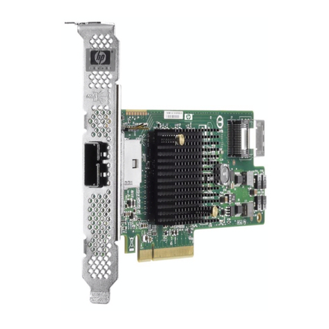
Figure 1-1 HP 8 Internal Port PCI-X SAS Controller
10 Controller Overview

Connectors and Indicators
Figure 1-2 illustrates the connectors and indicator LEDs on the HP 8 Internal Port PCI-X SAS
Controller. Table 1-1 describes each component.
Figure 1-2 Connectors and Indicators
Table 1-1 Component Descriptions
DescriptionNumber
Heartbeat LED (green/amber). Flashing green indicates normal operation. Amber indicates that
the card’s firmware has detected a fault.
1
Activity LED (green). Blinks when there is I/O activity on any port.2
Internal 4x SAS connector, port 1.3
Internal 4x SAS connector, port 2.4
See the server documentation for the location of HP 8 Internal Port Embedded SAS Controller
connectors and indicator LEDs.
Controller Description 11

12

2 Replacing a Controller
This chapter provides information on replacing an HP 8 Internal Port PCI-X SAS Controller. This
chapter includes the following topics:
“Replacement Overview” (page 13)
“Preparing the Server” (page 13)
“Replacing the Controller” (page 13)
“Completing the Controller Replacement” (page 14)
NOTE: The HP 8 Internal Port PCI-X SAS Controller is a factory-integrated core I/O card. Online
Addition, Deletion, and Replacement are not supported.
Replacement Overview
The installation procedure involves the following steps:
• Preparing the server.
• Replacing the controller.
• Completing the controller replacement.
Preparing the Server
To prepare the server for add or replacement, use the following steps:
1. Perform a normal system shutdown.
2. Power down the server.
3. Power down all peripheral devices attached to the server.
4. Unplug the AC power cord from the outlet, and then unplug it from the server.
5. Disconnect all peripheral devices attached to the server.
Replacing the Controller
WARNING! To reduce the risk of personal injury or damage to the equipment, consult the
safety information and user documentation provided with the server before attempting the
installation. Many servers are capable of producing energy levels that are considered hazardous
and are intended to be serviced only by qualified personnel who have been trained to deal with
these hazards. Do not remove enclosures or attempt to bypass any interlocks that may be provided
for the purpose of removing these hazardous conditions.
WARNING! WARNING! To reduce the risk of personal injury from hot surfaces, allow the
internal system components to cool before touching them.
CAUTION: Electrostatic discharge (ESD) can damage electronic components. Be sure that you
are properly grounded before beginning this procedure. For more information, see the
"Electrostatic Discharge" section of this guide.
To replace the PCI-X card, follow these steps:
1. Remove or open the server access panel and locate the PCI/PCI-X bus expansion slots.
For instructions on opening the server, see the server documentation at:
http://docs.hp.com/en/hw.html
2. Identify the controller that you need to replace.
Replacement Overview 13

3. Label the connectors to the internal drive bays. The connector closest to the mounting bracket
is Port 1, and the connector closest to the interior of the server is Port 2.
4. Disconnect the cables from the PCI-X card.
5. Depending on the server model, remove the retaining screw or open the expansion slot latch
that secures the PCI-X card.
6. Remove the card.
7. Insert the new card into the slot, and press it firmly into place. The contacts on the adapter
edge should be fully seated in the system board connector.
8. Depending on the server model, secure the adapter by replacing the retaining screw or by
closing the slot latch.
9. Reconnect the cables to the internal drive bays.
Completing the Controller Replacement
To complete the replacement and boot the server, follow these steps:
1. Verify that all cables are routed correctly and are not restricting or being pinched by other
components. For the correct routing of the cables, see the server documentation.
2. Replace or close the server access panel.
3. Reconnect the peripheral devices.
4. Reconnect the AC power cord.
5. Power on the peripheral devices.
6. Power on the server.
7. Configure the replacement controller.
See Chapter 3 (page 15).
8. Update the adapter firmware, if necessary.
14 Replacing a Controller

3 Configuring the Controller Offline
The following information provides steps needed to configure the SAS controller during
installation. This chapter includes the following topics:
“Integrated RAID” (page 15)
“The drvcfg Utility” (page 16)
“Example: Adding, Viewing, and Deleting An Integrated Mirror Volume Using drvcfg” (page 32)
“The cfggen Utility” (page 41)
“Updating SAS Controller Firmware Offline” (page 48)
Integrated RAID
Use Integrated RAID (IR) when the fault tolerance of a RAID configuration are required. The
components of IR are:
• Integrated Mirror (IM)
• Global Hot Spare
Use the drvcfg and cfggen EFI utilities to configure and maintain IR volumes offline. See “The
drvcfg Utility” (page 16), and “The cfggen Utility” (page 41).
Use the sasmgr HP-UX command to configure and maintain IR volumes online. See “The sasmgr
Command Set” (page 54).
Integrated Mirror
IM maintains a mirrored copy of the data in the array. An IM provides data protection for the
system boot volume to safeguard critical information such as the operating system on servers
and high performance workstations. An IM supports two simultaneous mirrored volumes,
making an array, providing fault-tolerant protection for critical data. Typically, one of these
volumes is the boot volume. If a disk in an IM fails, the hot swap capability enables you to easily
restore the volume by replacing the failed disk. The firmware then automatically re-mirrors to
the new disk.
Global Hot Spare
Each SAS controller can have one global hot spare disk available to automatically replace a failed
disk in the one or two IM volumes configured on the controller. The hot spare makes the IM
array more fault-tolerant. Up to two IM volumes are supported per SAS controller plus the hot
spare.
Configuration Utilities
Table 3-1 lists the offline and online utilities you can use to configure IM arrays on your HP
Integrity Server.
Table 3-1 SAS Controller Configuration Utilities
For more information
Online or
Offline
Operating System
or EnvironmentInterface TypeUtility Name
See ““The drvcfg Utility”.”OfflineEFIGUI
drvcfg
See “The cfggen Utility” (page 41).CLI
cfggen
See “The sasmgr Command Set” (page 54).OnlineHP-UX 11i v2 and
11i v3
CLI
sasmgr
Integrated RAID 15

The drvcfg Utility
This section describes in detail all of the available commands and options in the drvcfg utility.
For step-by-step examples of common configuration procedures using drvcfg, see:
•“Determining the Driver ID and Ctrl ID” (page 32).
•“Adding An Integrated Mirror Volume” (page 33).
•“Viewing the Properties of an Array” (page 37).
•“Deleting an Integrated Mirror Volume” (page 38).
Starting the drvcfg Utility
To start the drvcfg utility, follow these steps:
1. Power on or reboot the server.
2. Choose EFI shell from the console menu.
3. At the Shell> prompt, enter drvcfg -s and press Enter.
Using the drvcfg Utility With a Terminal Emulation Program
The drvcfg utility uses input keys (F1,F2,Home,End, etc.) that may not be supported by all
terminal emulation programs. Review the terminal emulation program documentation to
determine which input keys are supported. If you have problems using any of the Function keys
or navigation keys, use the alternate keys that are shown at the bottom of each drvcfg screen.
The following Function and navigation keys apply on all drvcfg screens:
F1 Help Context sensitive help for the field in which the cursor is located.
Arrow Keys Select Item - Up, down, left, right movement to position the cursor.
Home/End Select Item - Up, down, left, right movement to position the cursor.
+/- Change Item - Items with values in [brackets] are modifiable. Numeric keypad
+ and numeric keypad - (minus) update a modifiable field to its next relative
value.
Esc Abort/Exit - Aborts the current context operation, or exits the current screen. If
you have changed settings, you will be asked to confirm the exit. If you are
using a serial console, pressing the Esc key causes a delay of several seconds
before the takes effect. This is normal system behavior and is not an error.
Enter Execute <item> - Executable items are indicated by highlighted text and a
different background color. Press Enter to perform the field's function.
Configuration Utility Screens
SAS BIOS configuration utility screens contain the following areas, starting at the top of the
screen:
• Header area: Identifies the utility and version number.
• Menu area: Gives the title of the current screen, and on screens other than the Adapter List
screen also identifies the adapter.
• Main area: The main area for presenting data. This area has a cursor for item selection, and
horizontal and vertical scroll bars if necessary.
• Footer area: Provides general help text, and lists the available key commands.
Adapter List Screen
When you start drvcfg, the Adapter List appears:
16 Configuring the Controller Offline

The Adapter List screen displays a scrolling list of up to 256 SAS controllers in the system, and
provides information about each of them.
Use the arrow keys to select a SAS controller, and then press Enter to view and modify the
selected SAS controller's properties.
The status of each adapter may be Enabled or Disabled. You can view and modify the SAS
controller settings for adapters in either status. Use the Boot Support setting in the Adapter
Properties screen to change the status of this setting. The EFI Driver must reconnect for a new
Boot Support setting to take effect; this occurs automatically when you exit drvcfg.
The information fields on the Adapter List Screen are as follows:
Adapter Indicates the specific SAS Host Bus Adapter type.
PCI Bus Indicates the PCI Bus number assigned by the system BIOS to an adapter (0x00
- 0xFF, 0 - 255 decimal)
PCI Dev Indicates the PCI Device assigned by the system BIOS to an adapter (range
0x00 - 0x1F, 0 - 31 decimal)
PCI Fnc Indicates the PCI Function assigned by the system BIOS to an adapter (range
0x00 - 0x7, 0 - 7 decimal)
FW Revision Displays the Fusion MPT firmware version and type (IR or IT)
Status Indicates whether the adapter is eligible for software control: Enabled,
Disabled, or Error.
Enabled Indicates the EFI driver is controlling the adapter or will attempt
to control the adapter upon reload.
Disabled Indicates the EFI driver is not controlling the adapter or will
discontinue control of the adapter upon reload.
Error Indicates that the EFI driver encountered a problem with the
adapter. You can view and modify settings for the adapter but
the available information and functionality may be limited.
Adapter Properties Screen
After you select a SAS controller and press Enter,drvcfg scans the SAS controller and its
attached devices, and the Adapter Properties screen (similar to the following) appears. Use this
screen to view and modify adapter settings.
The drvcfg Utility 17

The information fields on the Adapter Properties screen are as follows:
Adapter Indicates the specific SAS Host Bus Adapter type.
PCI Address Displays the PCI address assigned by the system BIOS to the
adapter.
• Bus value range 0x00 - 0xFF, 0 - 255 decimal
• Device value range 0x00 - 0x1F, 0 - 31 decimal
• Function range 0x00 - 0x7, 0 - 7 decimal
MPT Firmware Revision Displays the MPT firmware version and type in the format
x.xx.xx.xx-yy, where x.xx.xx.xx indicates the firmware
version and yy indicates the type. In the example screen the
firmware version is 1.23.33.00 and the type is IR.
SAS Address Displays the SAS Address assigned to this adapter.
Status Indicates whether the adapter is eligible for configuration utility
software control or is reserved for control by other software:
Enabled, Disabled, or Error.
Enabled Indicates the EFI driver is controlling the adapter,
or will attempt to control the adapter upon
reload.
Disabled Indicates the EFI driver is not controlling the
adapter or will discontinue control of the adapter
upon reload.
Error Indicates that the EFI driver encountered a
problem with the adapter. You can view and
modify settings for the adapter but the available
information and functionality may be limited.
Boot Support Indicates whether the adapter is eligible for configuration utility
software control, or is reserved for control by other software:
Enabled BIOS & OS, Enabled BIOS Only, Enabled OS Only, or
Disabled.
18 Configuring the Controller Offline

Enabled BIOS & OS The SAS controller is controlled by
both the BIOS and OS driver
Enabled BIOS Only The SAS controller is controlled
only by the BIOS. This setting may
not be supported by all OS drivers.
For example, it is not possible to
disable an adapter in a Windows
driver.
Enabled OS Only SAS controller is controlled only by
the OS driver.
Disabled SAS controller is not controlled by
the BIOS when the SAS controller
is loaded. However, the adapter is
visible through the Configuration
Protocol.
Changes to the Boot Support setting are reflected in the Status
field of the Adapter List menu. However, the new setting does
not take effect until you reboot the system.
To access the following additional screens, use the arrow keys to highlight the option and press
Enter:
• RAID Properties. See “RAID Properties Screens.”
• SAS Topology. See “SAS Topology Screen.”
• Advanced Adapter Properties. See “Advanced Adapter Properties Screen” (page 26).
RAID Properties Screens
There are four screens within RAID properties, all of which are initially accessed by selecting
RAID Properties from the Adapter Properties screen. The first screen displayed is the Select
New Array Type screen:
The drvcfg Utility 19

Select New Array Type Screen
Use the Select New Array Type screen to view an existing array, or create an Integrated Mirror
array of two disks with an optional hot spare. See “Viewing the Properties of an Array” (page 37),
and “Adding An Integrated Mirror Volume” (page 33).
Create New Array Screen
The Create New Array screen is accessed by pressing Enter on the Create IM Volume field from
the Select New Array Type screen.
Use the following steps to create a new array:
1. Press Mto migrate to an IM array. This keeps the existing data, and the disk is synchronized.
2. Press Dto delete all data on all the disks in the array. This overwrites existing data when
creating a new IM array, and the disk is not synchronized.
3. After the volume is configured, press Cto create the array. The system prompts you to save
changes; if you do so, the array is created. During the creation process, the utility pauses.
You are then taken back to the Adapter Properties screen.
The following are the descriptions for the Create New Array Screen:
Array Type Indicates the type of array being created.
Array Size Indicates the size of the array in MB.
Bay Displays the bay in which devices are located.
Device Identifier Displays the device identifier.
RAID Disk Specifies the devices (disks) that make up an IM array. If RAID Disk
is “Yes,” the device is part of an IM array, if “No,” the device is not
part of an IM array. If this field is grayed out, one of the following
conditions applies:
• The device does not meet the minimum requirements for use in
an IM array.
• The device is not large enough to mirror existing data on the
primary drive.
• This disk has been selected as the Hot Spare for the IM array.
Hot Spr Specifies whether a device is the Hot Spare for an IM array. If Hot
Spr is “Yes,” the device will be used as a Hot Spare for the IM array,
if “No,” the device will not be used as a Hot Spare for the IM array.
Only one Hot Spare per IM array is permitted. A Hot Spare is not
required in an IM. A Hot Spare can be specified at array creation, or
at any time after creation, provided the array is made up of 5 disks
or fewer. If this field is grayed out, one of the following conditions
applies:
• The device does not meet the minimum requirements for use in
an IM array.
• The array already has a Hot Spare.
• The array is made up of the maximum number of devices (6).
• The device isn't large enough to mirror existing data on the
primary. The Hot Spare drive must be greater than or equal to
the size of any drive in any IM volume.
Drive Status One of the following will be displayed:
OK Disk is online and fully functional.
Missing Disk is not responding.
Failed Disk has failed.
20 Configuring the Controller Offline
Table of contents
Other HP Adapter manuals

HP
HP hn210p User manual

HP
HP Integrity BL860c Instruction Manual

HP
HP 561T User manual

HP
HP 652497-B21 User manual

HP
HP Mini 30W User manual

HP
HP Ethernet 10Gb 2-port 530T Adapter User manual

HP
HP NC364m User instructions

HP
HP A6829A User manual

HP
HP 411508-B21 - Smart Array E200/128 BBWC Controller... Reference manual

HP
HP NC552SFP User manual