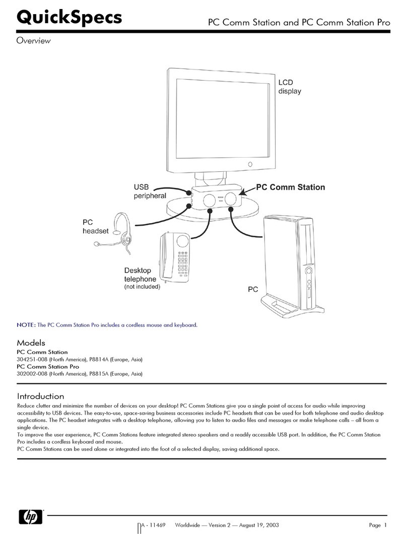
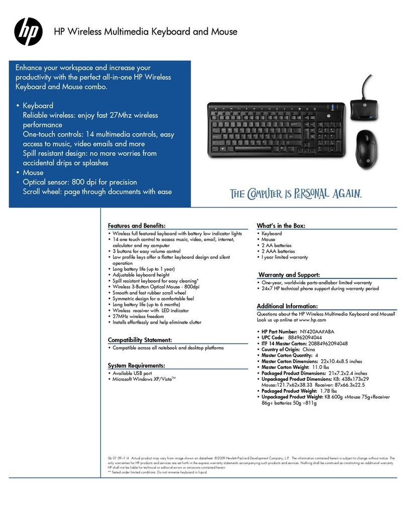
HP EISA/PCI Multiplexer User manual

January 1998
HP EISA/PCI Multiplexer Family Cabling,
Diagnostics and Troubleshooting Manual
**
HP Part Number: 5966-8703
Edition: Edition 1

© Copyright 1998 Hewlett-Packard Company
Legal Notices
The information in this document is subject to change without notice.
Hewlett-Packard makes no warranty of any kind with regard to this manual, including, but not limited to, the implied warranties of merchantability
and fitness for a particular purpose. Hewlett-Packard shall not be held liable for errors contained herein or direct, indirect, special, incidental or
consequential damages in connection with the furnishing, performance, or use of this material.
Warranty. A copy of the specific warranty terms applicable to your Hewlett- Packard product and replacement parts can be obtained from your
local Sales and Service Office.
Restricted Rights Legend. Use, duplication or disclosure by the U.S. Government is subject to restrictions as set forth in subparagraph (c) (1) (ii) of
the Rights in Technical Data and Computer Software clause at DFARS 252.227-7013 for DOD agencies, and subparagraphs (c) (1) and (c) (2) of
the Commercial Computer Software Restricted Rights clause at FAR 52.227-19 for other agencies.
HEWLETT-PACKARD COMPANY
nl
3000 Hanover
Street
nl
Palo Alto, California 94304
nl
U.S.A.
Use of this manual and flexible disk(s) or tape cartridge(s) supplied for this pack is restricted to this product only. Additional copies of the programs
may be made for security and back-up purposes only. Resale of the programs in their present form or with alterations, is expressly prohibited.
Copyright Notices. ©copyright 1983-98 Hewlett-Packard Company, all rights reserved.
Reproduction, adaptation, or translation of this document without prior written permission is prohibited, except as allowed under the copyright laws.
©copyright 1979, 1980, 1983, 1985-93 Regents of the University of California
This software is based in part on the Fourth Berkeley Software Distribution under license from the Regents of the University of California.
©copyright 1980, 1984, 1986 Novell, Inc.
©copyright 1986-1992 Sun Microsystems, Inc.
©copyright 1985-86, 1988 Massachusetts Institute of Technology.
©copyright 1989-93 The Open Software Foundation, Inc.
©copyright 1986 Digital Equipment Corporation.
©copyright 1990 Motorola, Inc.
©copyright 1990, 1991, 1992 Cornell University
©copyright 1989-1991 The University of Maryland
©copyright 1988 Carnegie Mellon University
Trademark Notices UNIX is a registered trademark of The Open Group.
X Window System is a trademark of the Massachusetts Institute of Technology.
MS-DOS and Microsoft are U.S. registered trademarks of Microsoft Corporation.
OSF/Motif is a trademark of the Open Software Foundation, Inc. in the U.S. and other countries.

Contents
Printing History.............................................................................................5
1 Overview..................................................................................................6
Hewlett Packard EISA/PCI Multiplexer Family...............................................................................6
Mux Cards..............................................................................................................................6
Mux 64 Card......................................................................................................................6
Mux 8 Card........................................................................................................................7
Peripheral Cabling...............................................................................................................7
Port Modules............................................................................................................................8
Fan Out Cable.........................................................................................................................8
2 Install Mux Card.......................................................................................10
Overview..............................................................................................................................10
EISA Mux Installation Procedure................................................................................................10
PCI Mux Installation Procedure.................................................................................................10
3 Install port modulesInstall Port Modules,Install fan out cable Fan Out Cable
&Install PS-4 Power Supply...........................................................................12
Overview..............................................................................................................................12
Mate and mount port modulesMate and Mount Port Modules.......................................................12
Connecting Port Modules to Mux 64 Card............................................................................13
Install the PS-4 power supplyInstall the Mux Power Supply............................................................13
Verify module LEDsVerify Module LEDs..................................................................................14
Install fan out cableInstall Fan Out Cable...................................................................................14
4 Port to Device Cabling..............................................................................16
Overview..............................................................................................................................16
DB-25 Port Module..................................................................................................................16
Device Wiring...................................................................................................................17
RJ-45 Port Module and Fan Out Cable......................................................................................19
Modular Cables ...............................................................................................................21
Converter Cables...............................................................................................................23
Cabling for UPS and Disc Arrays.........................................................................................24
5 Port naming and numberingPort Naming and Numbering..............................26
Overview..............................................................................................................................26
UNIX port assignmentsHP-UX Port Assignments ..........................................................................26
HP-UX Port Names.............................................................................................................26
Multiple HP Mux Card Installations.......................................................................................28
6 Troubleshooting and Diagnostics................................................................29
Overview..............................................................................................................................29
Troubleshooting......................................................................................................................29
Excessive Frequent getty Spawninggetty Spawning.................................................................29
Problem: .....................................................................................................................29
Cause: ........................................................................................................................29
Contents 3
Terminal Login Problems.....................................................................................................29
Problems: ....................................................................................................................29
Causes: ......................................................................................................................29
Tests:...........................................................................................................................30
Printer Problems.................................................................................................................30
Problems: ....................................................................................................................30
Causes: ......................................................................................................................30
Tests:...........................................................................................................................30
Modem Connection and Troubleshooting..............................................................................31
Modem Error MessagesModem Error Messages................................................................31
Error Message:.............................................................................................................31
Probable Cause:...........................................................................................................31
Error Message:.............................................................................................................31
Probable Cause: ..........................................................................................................31
Error Message:.............................................................................................................32
Probable Cause:...........................................................................................................32
System CrashesSystem Crashes or Panics..............................................................................32
DiagnosticsDiagnostics............................................................................................................32
Running emux_diag UtilityRunning emux_diag Utility...................................................................32
Driver StatusDriver Status MenuDriver Status Menu Selections.......................................................32
Driver Status......................................................................................................................33
Board StatusBoard Status...............................................................................................33
CountersCounters..........................................................................................................34
TopologyTopology.........................................................................................................35
Port Status MenuPort Status Menu Selections..........................................................................35
Breakout BoxBreakout Box..............................................................................................35
Data ScopeData Scope.................................................................................................36
TermioTermio................................................................................................................38
Register DumpRegister Dump..........................................................................................38
Diagnostics MenuDiagnostics Menu Selections.......................................................................39
LoopbackLoopback.......................................................................................................39
SendSend....................................................................................................................40
QuitQuit...........................................................................................................................40
A Host Cable..............................................................................................41
Overview..............................................................................................................................41
Host Cable Specifications........................................................................................................41
4 Contents

Printing History
The manual printing date and part number indicate its current edition. The printing date will change
when a new edition is printed. Minor changes may be made at reprint without changing the printing
date. the manual part number will change when extensive changes are made.
Manual updates may be issued between editions to correct errors or document product changes.
To ensure that you receive the updated or new editions, you should subscribe to the appropriate
product support service. See your HP sales representative for details.
First Edition: January 1998
5

1 Overview
Hewlett Packard EISA/PCI Multiplexer Family
The Hewlett Packard EISA/PCI Multiplexer (Mux) is a high-speed serial communications multiple
port product. It consists of several different modular components configured in a variety of
combinations to satisfy most applications. The major components are:
•EISA or PCI Mux 8 Card or Mux 64 Card
•Fan Out Cable or Port Module(s)
•Power Supply for Mux Port Modules
•RJ-45 to HP DB-25 Adapters and RJ-45 to HP RJ-45 Adapter
•Mux Software
Mux Cards
The Mux Card occupies a single EISA or PCI slot in the host computer and provides the intelligent
communications functions to "off-load" the CPU serial communications processing tasks.
Table 1 HP EISA/PCI Mux Card Models
Maximum Port
Speed
InterfaceDescriptionOrder
Number
230,400bpsFan Out CableEISA Mux 8 CardJ2482A
115,200bpsPort Module(s)EISA Mux 64 CardJ2483A
230,400bpsFan Out CablePCI Mux 8 CardJ3592A
115,200bpsPort Module(s)PCI Mux 64 CardJ3593A
There are two types of Mux Cards as listed in Table 1-1. The Mux 8 Card has an eight port RJ-45
fan out cable. The Mux 64 Card supports 16 to 64 ports by using up to four external Port Modules,
ordered separately. Every Mux Card has at least one SuperSerial Processor (SSP). This RISC
processor controls the flow of data through multiple communications ports.
Mux 64 Card
Figure 1-1 illustrates a Mux 64 Card. This card is capable of controlling the operation of up to 64
high speed serial ports.
Figure 1 Mux 64 Card
6 Overview

Mux 8 Card
Figure 1-2 illustrates a Mux 8 Card. This card is capable of controlling the operation of up to 8
high speed serial ports.
Up to four Mux 64 Cards per system or three Mux 64 Cards and one Mux 8 Card are supported
per system.
Figure 2 Mux 8 Card
Peripheral Cabling
Peripheral devices (such as terminals, printers, modems, bar code readers, cash registers, etc.)
are connected to fan out cables or port modules located outside of the computer system. Mux Port
modules require an AC/DC power supply.
Figure 1-3 illustrates a basic 16-port configuration. A 4-foot (1.2 m) host cable is supplied for
connecting the port module(s) to the Mux 64 Card.
Figure 3 Basic 16-port hardware configuration
Mux Cards 7

NOTE: Host cables up to 300 feet (91.5 m) can be built and used to connect the Mux Card and
first port module. Note that V-Class systems require a 25-foot (7.6m) host cable, product number
J3595A. Extended host cables can be used to connect and extend the distance up to 300 feet
between the first port module and subsequent port modules to make a daisy chain configuration.
(See Appendix A for host cable specifications.) Shielded cable is recommended.
Port Modules
Port modules are available with either DB-25 or RJ-45 female port connectors. Both types of port
modules may be freely intermixed on a host cable. A maximum of 4 port modules (64 ports) is
permitted for each Mux 64 card.
Table 2 HP Mux Port Modules
Maximum Port
Speed
InterfaceDescriptionOrder Number
115,200bpsRJ-45 RS-232PM16-RJJ2484A
115,200bpsRJ-45 RS-422PM16-RJ/422J2501A
115,200bpsDB-25 RS-232PM16-DBJ2485A
Figure 1-4 illustrates a 16 port DB-25 port module and a 16 port RJ-45 port module.
Figure 4 Port Modules DB-25 and RJ-45
Port module power is provided by an external power supply (J2483-60010) connected to the first
port module (see Figure 1-3). Power is passed from left to right through all directly mated modules.
Fan Out Cable
Mux 8 Cards have an RJ-45 RS-232 fan out cable. Each port on the fan out cable is a RJ-45 type
connector. Figure 1-5 illustrates a Mux 8 Card connected to a fan out cable.
8 Overview

Figure 5 Mux 8 Card with Fan Out Cable
RJ-45 to DB-25 adapter cables of various lengths can be built and used to connect the fan out
cable ports to various peripheral devices. See Chapter 4 for wiring information.
The J2484A port module and fan out cable use standard RS-232 pin outs. Modular adapters are
available for converting to HP proprietary RJ-45 or DB-25 pin outs (see Chapter 4).
Fan Out Cable 9

2 Install Mux Card
Overview
The procedures outlined in this chapter are applicable to the HP EISA Mux 8 Card and Mux 64
Card and the HP PCI Mux 8 Card and Mux 64 Card.
EISA Mux Installation Procedure
When adding new EISA Mux Cards to an existing system, use the following steps to install the
hardware and software:
•List each card and the number of the EISA slot in which it will be installed.
•Install the EISA Mux software using the swinstall program.
•Run the eisa_config program to add the EISA ID configuration to the slot number of each new
card.
(HWP1510 for the 8 port card;
HWP1520 for the 64 port card)
•Shut down the system.
•Install the Mux Cards in the appropriate slots and connect the port modules and power supplies,
if any.
•Power up the system. Device files will be created automatically.
•Enter the command below to check for Mux Card activation.
ioscan -f | grep tty
•Run emux_diag program to verify the topology of the port module connections.
•Finally, use the SAM utility to change the configuration or the device file, to enable hardware
handshaking and add getty entries.
•Run the command below each time a new port module is added to the Mux Card.
insf -e -d eisa_mux0
PCI Mux Installation Procedure
When adding new PCI Mux Cards to an existing system, use the following steps to install the
hardware and software:
•Install the PCI Mux software using the swinstall program.
•Shut down the system.
•Install the Mux Cards in the appropriate slots and connect the port modules and power supplies,
if any.
•Power up the system. Device files will be created automatically.
•Enter the command below to check for Mux Card activation.
ioscan -f | grep tty
•Run emux_diag program to verify the topology of the port module connections.
•Finally, use the SAM utility to change the configuration or the device file, to enable hardware
handshaking and add getty entries.
•Run the command below each time a new port module is added to the Mux Card.
insf -e -d pci_mux0
10 Install Mux Card

NOTE: If installing the Mux hardware before the Mux software use the following steps:
•List each card and the number of the EISA or PCI slot in which it will be installed.
•Install the Mux Cards in the appropriate slots and connect the port modules and power supplies,
if any.
•Power up the system.
•Install the Mux software using the swinstall program.
•Reboot the system again to activate the Mux Cards.
For additional information, refer to the appropriate HP 9000 systems I/O Card Upgrade Guide,
Configuring HP-UX for Peripherals, HP 9000 Managing HP-UX Software with SD-UX manual, the
EISA/PCI Mux Quick Installation Card, and the HP-UX Systems Administration Tasks manual.
PCI Mux Installation Procedure 11

3 Install Port Modules, Fan Out Cable & Power Supply
Overview
T his chapter describes the procedures to install port modules and connect fan out cables to HP
EISA/PCI Mux Cards. The procedure to install the power supply J2483-60010 for EISA/PCI Mux
port modules (J2484A/J2485A/J2501A) is also described.
Mate and Mount Port Modules
Multiple port modules mate together to permit simple expansion of the entire system without
disassembling the computer. Included with each port module are two L-shaped coupler brackets
and twelve screws (8 black-anodized and 4 nickel-plated). Mate and mount the port modules
using the following procedure:
1. Group the modules by mating them together as shown in Figure 3-1.
Figure 6 Mating two port modules
2. Attach coupler brackets as shown in Figure 3-2. Use the nickel-plated screws to secure the
coupler brackets to the back of the port module. Use the black-anodized screws to secure the
coupler brackets to the top and bottom of the port modules.
12 Install Port Modules, Fan Out Cable & Power Supply

Figure 7 Coupling and wall mounting two port modules
3. Also included with each port module are two wall mounting brackets and four screws. Attach
the mounting brackets to the appropriate modules and secure them to a surface as shown in
Figure 3-2 insert.
NOTE: To wall mount a single module, attach one bracket on the top and one bracket on
the bottom at opposite sides of the module.
Connecting Port Modules to Mux 64 Card
Connect port modules to the Mux 64 Card using the supplied host cable, J2483-60013 (4-feet)
or 3595-63001 (25-feet) or one you have made (see Appendix A).
A maximum of 4 port modules can be connected to the host cable as shown in Figure 3-3.
Figure 8 Port module HD-26 male connector
Install the Mux Power Supply
Install the power supply for the Mux port modules (see Figure 3-4) using the following procedure:
Install the Mux Power Supply 13

Figure 9 EISA/PCI Mux power supply
1. Remove the power plug cover protecting the power connector on the port module (Figure 3-5).
Figure 10 Port module power plug cover and LEDs
2. Inset the DC output cable plug, with latch (Figure 3-5 insert) of the plug facing the front of the
module, into the port module connector. Press down firmly until a snapping sound is heard.
3. Connect the cable for the power supply to an AC power outlet.
NOTE: Once the power supply is installed, any power source to the left of the port module
is automatically disconnected.
Verify Module LEDs
Each port module contains an online LED and power LED indicator (Figure 3-5). The online LED is
not functional until the driver software is installed. The power LED is illuminated when power is
present in the module.
Install Fan Out Cable
Install the fan out cable (J2482-60013) by connecting the DB-78 connector to the installed HP
EISA/PCI Mux 8 Card (Figure 3-6).
14 Install Port Modules, Fan Out Cable & Power Supply

Figure 11 Install Fan-out Cables
Install Fan Out Cable 15

4 Port to Device Cabling
Overview
This chapter details the pin-outs for the ports and cabling needed to connect the communications
ports to the peripheral devices.
NOTE: All RS-232 ports provide a standard RS-232 interface with full modem control signals
and surge protection on every signal. All RS-422 ports are data-only with no modem control signals.
DB-25 Port Module
DB25 ports provide standard RS-232 DTE signals on all DB-25 female connectors. One for each
connected device (see Figure 4-1).
Figure 12 DB-25 port module connector orientation
The pinouts for connectors on the DB-25 port modules are identical (Figure 4-2).
16 Port to Device Cabling

Figure 13 DB-25 connector pinouts
Device Wiring
Device wiring is dependent on the specific signal requirements of the system peripheral devices.
Cable connectors plugged into the DB-25 port module ports must have a male DB-25 connector.
The connector on the opposite end of each cable should mate to the peripheral device port (terminal,
printer, personal computer or modem).
Depending on the specific signal requirements of the system peripheral devices, 3-, 4-, or 7-wire
connections can be made. Figures 4-3 through 4-5 show the cable configurations for these
connections. Figure 4-6 shows the pinouts for a modem cable.
DB-25 Port Module 17

Figure 14 Cable pinouts - terminals and printers - XON/XOFF flow control
Figure 15 Cable pinouts - terminals and printers - Pin 20 hardware flow control
18 Port to Device Cabling

Figure 16 Cable pinouts - full modem control - terminal or printer
Figure 17 Pinouts for modem cables
RJ-45 Port Module and Fan Out Cable
RJ-45 port modules (J2484A) and fan out cable ports provide standard RS- 232 (RS-422 for J2501A
port modules) DTE signals on all RJ-45 female connectors, one for each connected device (see
Figure 4-7).
RJ-45 Port Module and Fan Out Cable 19

Figure 18 RJ-45 port module connector orientation and fan out cable
The pinouts for all RJ-45 jacks are shown below (see Figure 4-8).
Figure 19 RJ-45 jack pinouts
NOTE: In RS-422 terminology, RX- is sometimes labeled as RX(a) or Receive(a), while TX- is often
labeled as TX(a) or Transmit(a). The RX- signal should be attached from the port module to the TX-
signal of the device.
Please note the following cabling considerations:
•All jacks on the RJ-45 port module face the front of the product with the key pointed down.
Refer to Figure 4-7 for the modular jack wiring orientation.
•Either twisted-pair or flat modular cable may be used as a signal path from RJ-45 port module
or fan out cable ports to peripheral devices. However, twisted-pair cables significantly increase
the operating distance between ports and peripheral devices. Flat modular cable may reduce
the operating distance.
20 Port to Device Cabling
Table of contents
Other HP Computer Accessories manuals

HP
HP nx9100 - Notebook PC User manual

HP
HP x4500 Specification sheet

HP
HP P5911A - Cordless Keyboard And Mouse Technical manual

HP
HP 5219URF Instruction Manual

HP
HP Xw6200 - Workstation - 2 GB RAM User manual

HP
HP Xw4550 - Workstation - 2 GB RAM User manual

HP
HP 5992-3838 User manual

HP
HP FQ481AA - Wireless Elite Desktop Keyboard User manual

HP
HP Comm Station User manual

HP
HP Integrity cx2600 User manual