manuals.online logo
Brands
  1. Home
  2. •
  3. Brands
  4. •
  5. HP
  6. •
  7. Desktop
  8. •
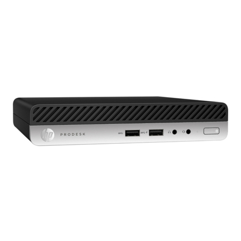
  9. HP ProOne 400 G3 Installation instructions

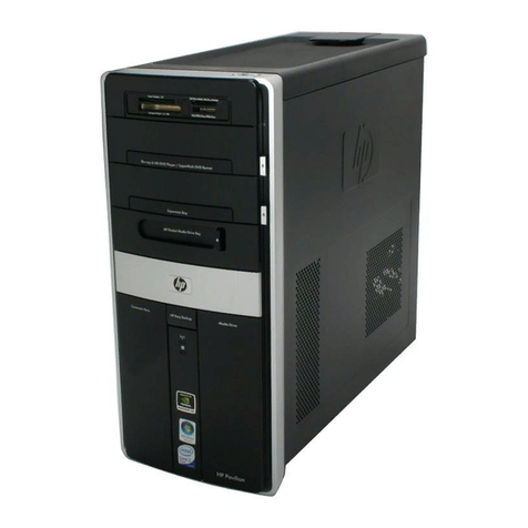
HP ProOne 400 G3 Installation instructions

Other HP Desktop manuals

HP dx2300 - Microtower PC Setup guide

HP

HP dx2300 - Microtower PC Setup guide

HP Kayak XU700 User manual

HP

HP Kayak XU700 User manual

HP Xw8200 - Workstation - 1 GB RAM User manual

HP

HP Xw8200 - Workstation - 1 GB RAM User manual

HP Xw4300 - Workstation - 2 GB RAM User manual

HP

HP Xw4300 - Workstation - 2 GB RAM User manual

HP c3700 - Workstation User manual

HP

HP c3700 - Workstation User manual

HP Xw6200 - Workstation - 2 GB RAM Reference manual

HP

HP Xw6200 - Workstation - 2 GB RAM Reference manual

HP Compaq 6000 Pro SFF User manual

HP

HP Compaq 6000 Pro SFF User manual

HP Compaq Presario Specification sheet

HP

HP Compaq Presario Specification sheet

HP A320m - Pavilion - 256 MB RAM Installation instructions

HP

HP A320m - Pavilion - 256 MB RAM Installation instructions

HP VL600 - Vectra - 128 MB RAM Product manual

HP

HP VL600 - Vectra - 128 MB RAM Product manual

HP A320m - Pavilion - 256 MB RAM User manual

HP

HP A320m - Pavilion - 256 MB RAM User manual

HP vectra vl420 User manual

HP

HP vectra vl420 User manual

HP A524x - Pavilion - 512 MB RAM User manual

HP

HP A524x - Pavilion - 512 MB RAM User manual

HP Vectra VE6 8 User manual

HP

HP Vectra VE6 8 User manual

HP Elite Tower 600 G9 Assembly instructions

HP

HP Elite Tower 600 G9 Assembly instructions

HP Compaq Presario Specification sheet

HP

HP Compaq Presario Specification sheet

HP Compaq d538 SFF Operating and maintenance manual

HP

HP Compaq d538 SFF Operating and maintenance manual

HP Compaq SP750 User manual

HP

HP Compaq SP750 User manual

HP Kayak XA-s Series 02 Manual

HP

HP Kayak XA-s Series 02 Manual

HP Pavilion 23 TouchSmart Installation instructions

HP

HP Pavilion 23 TouchSmart Installation instructions

HP Compaq dc7100 DT Manual

HP

HP Compaq dc7100 DT Manual

HP Vectra VE 5/xx Series User manual

HP

HP Vectra VE 5/xx Series User manual

HP Model 745 - VME Workstation User manual

HP

HP Model 745 - VME Workstation User manual

HP A1710n - Pavilion - 1 GB RAM User manual

HP

HP A1710n - Pavilion - 1 GB RAM User manual

Popular Desktop manuals by other brands

StarTech.com ARMSTSL manual

StarTech.com

StarTech.com ARMSTSL manual

Dell Inspiron 5720 quick start guide

Dell

Dell Inspiron 5720 quick start guide

GÜDE WERKBANK GW 6/2 XL Translation of the original instructions

GÜDE

GÜDE WERKBANK GW 6/2 XL Translation of the original instructions

Lenovo ThinkCentre M62z Vodič za uporabnika

Lenovo

Lenovo ThinkCentre M62z Vodič za uporabnika

Lenovo ThinkCentre M71z user guide

Lenovo

Lenovo ThinkCentre M71z user guide

Fujitsu ESPRIMO C7xx operating manual

Fujitsu

Fujitsu ESPRIMO C7xx operating manual

Bosch DCU 130 operating instructions

Bosch

Bosch DCU 130 operating instructions

Zotac VR GO quick start guide

Zotac

Zotac VR GO quick start guide

Sony VAIO VGC-LS21 Specifications

Sony

Sony VAIO VGC-LS21 Specifications

IBM PS/2 60 Hardware maintenance service

IBM

IBM PS/2 60 Hardware maintenance service

Acer Aspire SA60 Service guide

Acer

Acer Aspire SA60 Service guide

Lenovo ThinkCentre M71z Uživatelská příručka

Lenovo

Lenovo ThinkCentre M71z Uživatelská příručka

IBM Aptiva 2198 reference guide

IBM

IBM Aptiva 2198 reference guide

Sony PCV-LX810 - Vaio Slimtop Computer System reference manual

Sony

Sony PCV-LX810 - Vaio Slimtop Computer System reference manual

Dell Precision U3525 Quick reference guide

Dell

Dell Precision U3525 Quick reference guide

MicroTouch IC-215P-AW2 user guide

MicroTouch

MicroTouch IC-215P-AW2 user guide

Lenovo PC 300PL manual

Lenovo

Lenovo PC 300PL manual

Asus E210 Series user guide

Asus

Asus E210 Series user guide

manuals.online logo
manuals.online logoBrands
  • About & Mission
  • Contact us
  • Privacy Policy
  • Terms and Conditions

Copyright 2025 Manuals.Online. All Rights Reserved.

EL-MF877-00 Page 1
Template Revision B
PSG instructions for this template are available at EL-MF877-01
Product End-of-Life Disassembly Instructions
Product Category: Personal Computers
Marketing Name / Model
[List multiple models if applicable.]
HP ProOne 400 G3 Touch All-in-One Business PC
Purpose: The document is intended for use by end-of-life recyclers or treatment facilities. It provides the basic instructions
for the disassembly of HP products to remove components and materials requiring selective treatment, as defined by EU
directive 2002/96/EC, Waste Electrical and Electronic Equipment (WEEE).
1.0 Items Requiring Selective Treatment
1.1 Items listed below are classified as requiring selective treatment.
1.2 Enter the quantity of items contained within the product which require selective treatment in the right column, as
applicable.
Item Description
Notes
Quantity
of items
included
in product
Printed Circuit Boards (PCB) or Printed Circuit
Assemblies (PCA)
With a surface greater than 10 sq cm
1
Batteries
All types including standard alkaline and lithium coin
or button style batteries
1
Mercury-containing components
For example, mercury in lamps, display backlights,
scanner lamps, switches, batteries
0
Liquid Crystal Displays (LCD) with a surface greater
than 100 sq cm
Includes background illuminated displays with gas
discharge lamps
1
Cathode Ray Tubes (CRT)
0
Capacitors / condensers (Containing PCB/PCT)
0
Electrolytic Capacitors / Condensers measuring
greater than 2.5 cm in diameter or height
9
External electrical cables and cords
Power cord
1
Gas Discharge Lamps
0
Plastics containing Brominated Flame Retardants
weighing > 25 grams (not including PCBs or PCAs
already listed as a separate item above)
0
Components and parts containing toner and ink,
including liquids, semi-liquids (gel/paste) and toner
Include the cartridges, print heads, tubes, vent
chambers, and service stations.
0
Components and waste containing asbestos
0
Components, parts and materials containing
0
EL-MF877-00 Page 2
Template Revision B
PSG instructions for this template are available at EL-MF877-01
refractory ceramic fibers
Components, parts and materials containing
radioactive substances
0
2.0 Tools Required
List the type and size of the tools that would typically be used to disassemble the product to a point where components
and materials requiring selective treatment can be removed.
Tool Description
Tool Size (if
applicable)
Electric screwdriver (Torx)
T15, Torx
Electric screwdriver (Cross)
#0, Cross
Plastic stick
Description #4
Description #5
3.0 Product Disassembly Process
3.1 List the basic steps that should typically be followed to remove components and materials requiring selective treatment:
1. Follow steps described in Disassembly instruction (file attached)
2. If parts can be removed without using a tool, remove it first
3. Use correct screwdriver and torque value before unlock the screw.
4.
5.
6.
7.
8.
9.
3.2 Optional Graphic. If the disassembly process is complex, insert a graphic illustration below to identify the items
contained in the product that require selective treatment (with descriptions and arrows identifying locations).
MANUFACTURING PROCESS INSTRUCTIONS
MECHANICAL ASSEMBLY
MODEL : Pyxis400
1.00
Station Version Station Version Station Version Station Version Station Version Station Version
11.00 91.00 17 1.00 25 1.00 33 1.00
2 1.00 10 1.00 18 1.00 26 1.00
3 1.00 11 1.00 19 1.00 27 1.00
4 1.00 12 1.00 20 1.00 28 1.00
5 1.00 13 1.00 21 1.00 29 1.00
6 1.00 14 1.00 22 1.00 30 1.00
7 1.00 15 1.00 23 1.00 31 1.00
8 1.00 16 1.00 24 1.00 32 1.00
Station
Ver.
ALL 1.**
2017/5/23
Date
Content
Date:
Porter Zan
First version
2017/5/23
A.Current station version list:
B.Version Modify list:
Sub-assembly name:
Pyxis400 DISASS'Y SOP
Document No.:
Pyxis400 DISASS'Y SOP
Page:
Design
Revision:
Written by:
Ethan Lai
1 of 1
Auditor :Xin-Xin Chen
Tabulator:
Ethan Lai
Standard Operation Procedure
Tabulator:Issue Department:
Xin-Xin Chen NPSU-PPE
Auditor :
Ethan Lai
Steps:
Document No. : Pyxis400 DISASS’Y SOP Station :
Operation Name : Ver. : Date :
Note: If finding anything uncommon, notice foreman or assistant at once.
Fixture list (Specification) Qty. Fixture list (Specification) Qty.
Remove Stand & pull open Rear Cover
1. Take out Stand and put into the material box
(Fig. 1).
Follow the steps as Fig. 1, push the latch
upward, then pull up the hinge.
2. Pull open Rear Cover (Fig. 2, 3).
Follow the steps as Fig. 2 & 3, use the stick
to pull open the region of gap for lever force
to unfix Rear Cover.
Glove Requirements: Half-fingered gloves
Fig. 1
Fig. 2
1(1/1)
2017/5/23
1.00
Plastic stick 1
Fig. 3
Step1: Push the
latch upward
Step2: Pull up the hinge
1
Plastic stick
Force direction
Standard Operation Procedure
Tabulator:Issue Department:
Xin-Xin Chen NPSU-PPE
Auditor :
Ethan Lai
Steps:
Document No. : Pyxis400 DISASS’Y SOP Station :
Operation Name : Ver. : Date :
Note: If finding anything uncommon, notice foreman or assistant at once.
Fixture list (Specification) Qty. Fixture list (Specification) Qty.
Take out Rear Cover
1. Take out Rear Cover (Fig. 1, 2, 3).
Follow the steps as Fig. illustrated.
Have one hand to hold the system, and the
other hand to pull the edge of Rear Cover for
release
2. Put Rear Cover into the material box.
Glove Requirements: Half-fingered gloves
Fig. 1
2(1/1)
2017/5/23
1.00
Fig. 3
Pull up the two
sides of Rear Cover,
then take out.
Press downward Pull upward
Press downward
Pull upward
Fig. 2
Standard Operation Procedure
Tabulator:Issue Department:
Xin-Xin Chen NPSU-PPE
Auditor :
Ethan Lai
Steps:
Document No. : Pyxis400 DISASS’Y SOP Station :
Operation Name : Ver. : Date :
Note: If finding anything uncommon, notice foreman or assistant at once.
Fixture list (Specification) Qty. Fixture list (Specification) Qty.
3(1/1)
2017/5/23
1.00
Glove Requirements: Full-fingered gloves
Electric Screwdriver (S-6000MS) 1
Bits Type: T15,φ=5mm,L=60mm 1
Take out M/B shielding
Fig. 1
1. Unscrew (Torx Pin-Head ×4) all joints to take
out M/B shielding (Fig. 1).
Torsion: 4.0 ±1.0 kgf.cm
Take the screwdriver vertically to the screw
holes.
The screw holes are marked in red circles.
Standard Operation Procedure
Tabulator:Issue Department:
Xin-Xin Chen NPSU-PPE
Auditor :
Ethan Lai
Steps:
Document No. : Pyxis400 DISASS’Y SOP Station :
Operation Name : Ver. : Date :
Note: If finding anything uncommon, notice foreman or assistant at once.
Fixture list (Specification) Qty. Fixture list (Specification) Qty.
4(1/1)
2017/5/23
1.00
Glove Requirements: Full-fingered gloves
Electric Screwdriver (S-6000MS) 1
Bits Type: T15,φ=5mm,L=60mm 1
Take out Thermal Module
Fig. 1
1. Unscrew (Torx Pin-Head ×5) all joints to take
out Thermal Module (Fig. 1).
Torsion: 4.0 ±1.0 kgf.cm
Take the screwdriver vertically to the screw
holes.
2. Put Thermal Module into the material box.
Standard Operation Procedure
Tabulator:Issue Department:
Xin-Xin Chen NPSU-PPE
Auditor :
Ethan Lai
Steps:
Document No. : Pyxis400 DISASS’Y SOP Station :
Operation Name : Ver. : Date :
Note: If finding anything uncommon, notice foreman or assistant at once.
Fixture list (Specification) Qty. Fixture list (Specification) Qty.
Take out HDD and ODD
5(1/1)
2017/5/23
1.00
Glove Requirements: Half-finger gloves
1. Take out HDD (Fig. 1).
Pull open the HDD bracket softly to the right,
and push upward HDD to disconnect, then
put it into the material box.
2. Take out ODD (Fig. 2).
Press the latch and push ODD to the left
simultaneously to disconnect, then put ODD
into the material box.
Fig. 1
Fig. 2
Latch
Push
Standard Operation Procedure
Tabulator:Issue Department:
Xin-Xin Chen NPSU-PPE
Auditor :
Ethan Lai
Steps:
Document No. : Pyxis400 DISASS’Y SOP Station :
Operation Name : Ver. : Date :
Note: If finding anything uncommon, notice foreman or assistant at once.
Fixture list (Specification) Qty. Fixture list (Specification) Qty.
6(1/1)
2017/5/23
1.00
Glove Requirements: Half-fingered gloves
Electric Screwdriver (S-3000MS) 1
Bits Type: T15,φ=5mm,L=60mm 1
Take out I/O board
Fig. 2
1. Unscrew (Torx Pin-Head ×2) all joints to take
out I/O board and disconnect I/O cable (Fig.
1, 2).
Torsion: 4.0 ±1.0 kgf.cm
Take the screwdriver vertically to the screw
holes.
Put I/O board and two screws into the
material box.
2. Be careful not to make the pin heads of the
I/O connector are crooked (Fig. 3).
Pull out the I/O cable vertically from the top
of the I/O connector.

Fig. 1
Fig. 3
Standard Operation Procedure
Tabulator:Issue Department:
Xin-Xin Chen NPSU-PPE
Auditor :
Ethan Lai
Steps:
Document No. : Pyxis400 DISASS’Y SOP Station :
Operation Name : Ver. : Date :
Note: If finding anything uncommon, notice foreman or assistant at once.
Fixture list (Specification) Qty. Fixture list (Specification) Qty.
Take out DDR and CPU
1
7(1/1)
2017/5/23
1.00
Ion fan 1
CPU DISASS’Y fixture 1
Glove Requirements: Half-finger gloves
1. Take out DDR and put it into the material box
(Fig. 1).
Expand the springs on the both sides of the
DDR socket.
2. Take out CPU illustrated as Fig. 2, then put it
into the tray.
Don’t touch the pin heads of CPU.
Open the bracket by pulling off the link and
take out CPU.
Fig. 1
DDR
2. Open the bracket
by pulling off the link
1. Press the link and
push it to the right
Press the fixture, then
take out CPU vertically
CPU DISASS’Y steps:
Diagonally
consistent
Fig. 2