manuals.online logo
Brands
  1. Home
  2. •
  3. Brands
  4. •
  5. HP
  6. •
  7. Laptop
  8. •
  9. HP ProBook 635 Aero G7 Assembly instructions

HP ProBook 635 Aero G7 Assembly instructions

EL-MF877-00 Page 1
Template Revision C
Last revalidation date 04-01-2018
HPI instructions for this template are available at EL-MF877-01
Product End-of-Life Disassembly Instructions
Product Category: Notebooks and Tablet PCs
Marketing Name / Model
[List multiple models if applicable.]
HP ProBook 635 Aero G7 Notebook PC
HP ProBook 635 Aero G7
HP ProBook 635 Aero G8 Notebook PC
HP ProBook 635 Aero G8
HP mt32 Mobile Thin Client
HP mt32
HSN-I39C
Purpose: The document is intended for use by end-of-life recyclers or treatment facilities. It provides the basic instructions for the
disassembly of HPI products to remove components and materials requiring selective treatment, as defined by EU directive
2002/96/EC, Waste Electrical and Electronic Equipment (WEEE).
NOTE: Recyclers should sort plastic materials into resin streams for recycling based on the ISO 11469 plastic marking code on the
plastic part. For any questions on plastic marking, please contact HP’s Sustainability Contact.
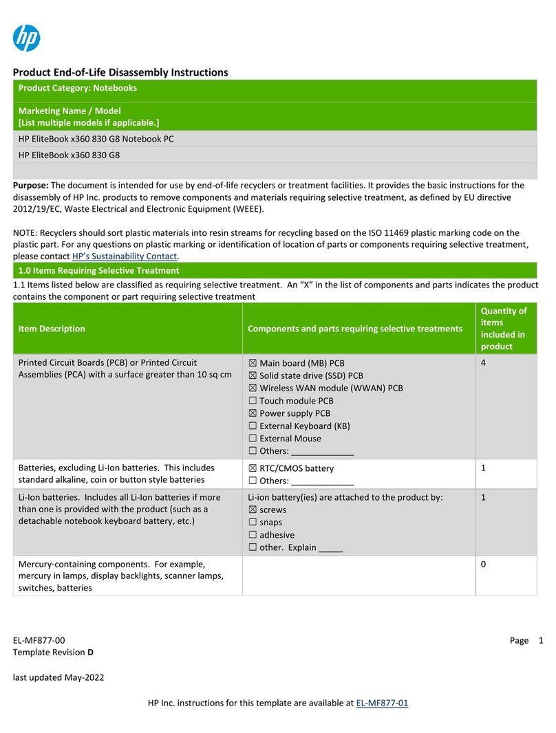
1.0 Items Requiring Selective Treatment
1.1 Items listed below are classified as requiring selective treatment.
1.2 Enter the quantity of items contained within the product which require selective treatment in the right column, as applicable.
Item Description Notes
Quantity of
items
included in
product
Printed Circuit Boards (PCB) or Printed Circuit
Assemblies (PCA)
With a surface greater than 10 sq cm
4
Batteries, excluding Li-Ion batteries. All types including standard alkaline, coin or button style
batteries
1
Li-Ion batteries. Include all Li-Ion batteries if more than
one is provided with the product (such as a detachable
notebook keyboard battery, RTC coin cell, etc.)
Battery(ies) are attached to the product by (check all
that apply with an “x” inside the “[ ]”):
[x] screws
[ ] snaps
[ ] adhesive
[ ] other. Explain
NOTE: Add detailed removal procedures including
required tools in the sections 3.1/3.2.
1
Mercury-containing components
For example, mercury in lamps, display backlights,
scanner lamps, switches, batteries
0
Liquid Crystal Displays (LCD) with a surface greater than
100 sq cm
Includes background illuminated displays with gas
discharge lamps (15.6”)
1
Cathode Ray Tubes (CRT)
0
Capacitors / condensers (Containing PCB/PCT)
0
EL-MF877-00 Page 2
Template Revision C
Last revalidation date 04-01-2018
HPI instructions for this template are available at EL-MF877-01
Item Description Notes
Quantity of
items
included in
product
Electrolytic Capacitors / Condensers measuring greater
than 2.5 cm in diameter or height
0
External electrical cables and cords
DC Cable for External Power Supply
1
Gas Discharge Lamps
0
Plastics containing Brominated Flame Retardants
weighing > 25 grams (not including PCBs or PCAs
already listed as a separate item above)
Components and parts containing toner and ink,
including liquids, semi-liquids (gel/paste) and toner
Include the cartridges, print heads, tubes, vent
chambers, and service stations.
0
Components and waste containing asbestos
0
Components, parts and materials containing refractory
ceramic fibers
0
Components, parts and materials containing
radioactive substances
0
2.0 Tools Required
List the type and size of the tools that would typically be used to disassemble the product to a point where components and
materials requiring selective treatment can be removed.
Tool Description
Tool Size (if
applicable)
Screw driver
Cross
Opening pry jig
Hot air gun or Hair dryer
Tweezer
3.0 Product Disassembly Process
3.1 List the basic steps that should typically be followed to remove components and materials requiring selective treatment
including the required steps to remove the external enclosure:
1. Loosen screws and remove base cover
2. Remove main battery
3. Remove DDR and small cards
4. Disconnect all cables and remove RTC battery
5. Take out Thermal module, fan and PCA
6.
7.
3.2 Optional Graphic. If the disassembly process is complex, insert a graphic illustration below to identify the items contained in the
product that require selective treatment (with descriptions and arrows identifying locations).
EL-MF877-00 Page 3
Template Revision C
Last revalidation date 04-01-2018
HPI instructions for this template are available at EL-MF877-01
Prepared by:Zhou.Gui-ling
Checked by:Luo.Allen
MANUFACTURING PROCESS INSTRUCTIONS
MECHANICAL ASSEMBLY
1.00
Station
Version
Station
Version
Station
Version
Station
Version
Station
Version
Station
Version
1 1.00 11 1.00 21 1.00
2 1.00 12 1.00 22 1.00
3 1.00 13 1.00 23 1.00
4 1.00 14 1.00 24 1.00
5 1.00 15 1.00 25 1.00
6 1.00 16 1.00 26 1.00
7 1.00 17 1.00 27 1.00
8 1.00 18 1.00 28 1.00
9 1.00 19 1.00
10 1.00 20 1.00
Station
Ver.
ALL 1.**
Page:
1 of 30
Sub-assembly name:
Grizzly disassembly SOP
Document No.:
Grizzly disassembly SOP
A.Current station version list:
B.Version Modify list:
Date
Content
Design
Written by:
Charles.Wang
Revision:
Date:
2020/9/15
2020/9/15
Initial
Charles.Wan
MODEL : Grizzly
Standard Operation Procedure
Document No. : Grizzly disassembly SOP Station:
Operation Name : Ver. : Edit date:
Fixture list (Spec.) Qty
Step:
Notice: Please inform production line leader or master if you found any abnormal..
Issued:Prepared:Zhou.gui-ling IE department
Safe Order Hear Look Do Static
Qual
ity
Fixtur
e
Symbol
Release Base screw
1. Loosen Base screw *5pcs as below picture showing.
❖Torque:2.5 ±0.2 kgf.cm
❖screw can not be slipped.
1(1/1)
Screw driver 1
1.00 2020/09/15
1
2
54
3
Standard Operation Procedure
Document No. : Grizzly disassembly SOP Station:
Operation Name : Ver. : Edit date:
Fixture list (Spec.) Qty
Step:
Notice: Please inform production line leader or master if you found any abnormal..
Issued:Prepared:Zhou.gui-ling IE department
Safe Order Hear Look Do Static
Qual
ity
Fixtur
e
Symbol
Disassembly Base 2(1/1)
1. Use cable jig to separate Base from unit.
Attention: Insert jig to TOP & Base gap area, then slide jig to separate TOP & Base.
2. Put hands on Base and TOP corner area, handle Base lift it up while press TOP
down.
3. Take away the Base from unit.
Cable jig 1
1.00
1
23
2020/09/15
Standard Operation Procedure
Document No. : Grizzly disassembly SOP Station:
Operation Name : Ver. : Edit date:
Fixture list (Spec.) Qty
Step:
Notice: Please inform production line leader or master if you found any abnormal..
Issued:Prepared:Zhou.gui-ling IE department
Safe Order Hear Look Do Static
Qual
ity
Fixtur
e
Symbol
Disassembly speaker 3(1/1)
1. Pullout battery cable from connector as Pic.1.
2. Pullout speaker cable from connector as Pic.2.
3. Take away L/R speaker from unit.
L/R speaker
Take away speaker
Pic.1
Pic.2 Pic.3 Pic.4
Pic.5
1.00
Speaker cable
2020/09/15
Standard Operation Procedure
Document No. : Grizzly disassembly SOP Station:
Operation Name : Ver. : Edit date:
Fixture list (Spec.) Qty
Step:
Notice: Please inform production line leader or master if you found any abnormal..
Issued:Prepared:Zhou.gui-ling IE department
Safe Order Hear Look Do Static
Qual
ity
Fixtur
e
Symbol
Disassembly battery 4(1/1)
1. Loosen Battery screw *4pcs as below picture
showing.
❖Torque:2.0 ±0.2 kgf.cm
❖screw can not be slipped.
2. Take out battery from unit.
Release screw and
take away battery
4
23
1
Screw driver 1
1.00 2020/09/15
Standard Operation Procedure
Document No. : Grizzly disassembly SOP Station:
Operation Name : Ver. : Edit date:
Fixture list (Spec.) Qty
Step:
Notice: Please inform production line leader or master if you found any abnormal..
Issued:Prepared:Zhou.gui-ling IE department
Safe Order Hear Look Do Static
Qual
ity
Fixtur
e
Symbol
Disassembly DDR&SSD shielding can 5(1/1)
1.Holder the shielding can handle mylar, then
lift it up to release shielding can from clip.
Handle mylar
Handle mylar
1.00 2020/09/15
Standard Operation Procedure
Document No. : Grizzly disassembly SOP Station:
Operation Name : Ver. : Edit date:
Fixture list (Spec.) Qty
Step:
Notice: Please inform production line leader or master if you found any abnormal..
Issued:Prepared:Zhou.gui-ling IE department
Safe Order Hear Look Do Static
Qual
ity
Fixtur
e
Symbol
Disassembly DDR 6(1/1)
1. Disassembly DDR from unit as Pic.1.
2. Take away mylar that stick on WWAN card connector as Pic.2.
Disassembly
DDR Take away
mylar
Pic.1 Pic.2
1.00 2020/09/15
Standard Operation Procedure
Document No. : Grizzly disassembly SOP Station:
Operation Name : Ver. : Edit date:
Fixture list (Spec.) Qty
Step:
Notice: Please inform production line leader or master if you found any abnormal..
Issued:Prepared:Zhou.gui-ling IE department
Safe Order Hear Look Do Static
Qual
ity
Fixtur
e
Symbol
Disassembly CAM cable & DC-in cable 7(1/1)
1. Loosen DC-in cable screw *1pcs and disassembly cable from connector, then take
out DC-in cable from unit as Pic.2 showing.
❖Torque:1.5 ±0.2 kgf.cm
❖screw can not be slipped.
2. Disassembly camera cable from connector as Pic.2.
1.00
Disassembly
camera cable
Pic.2
Pic.1
Take out DC-in
cable
Release screw
2020/09/15
Standard Operation Procedure
Document No. : Grizzly disassembly SOP Station:
Operation Name : Ver. : Edit date:
Fixture list (Spec.) Qty
Step:
Notice: Please inform production line leader or master if you found any abnormal..
Issued:Prepared:Zhou.gui-ling IE department
Safe Order Hear Look Do Static
Qual
ity
Fixtur
e
Symbol
Disassembly antenna & EDP cable
8(1/1)
1. Disassembly antenna from WWAN Module pin,
and take out antenna from hook as Pic.1 & Pic.2
2. Disassembly EPD cable from connector and
take out from cable trough as Pic.3 & Pic.4.
1.00
Disassembly antenna
Pin from WWAN Module
Take out antenna from hook
Disassembly
EDP cable
Take out
EDP cable
Pic.4
Pic.3
Pic.2
Pic.1
2020/09/15
Standard Operation Procedure
Document No. : Grizzly disassembly SOP Station:
Operation Name : Ver. : Edit date:
Fixture list (Spec.) Qty
Step:
Notice: Please inform production line leader or master if you found any abnormal..
Issued:Prepared:Zhou.gui-ling IE department
Safe Order Hear Look Do Static
Qual
ity
Fixtur
e
Symbol
Disassembly WLAN antenna 9(1/1)
1. Disassembly antenna from WLAN Module
pin, and take out antenna from cable trough.
1.00
Disassembly
antenna
Take out antenna
from cable trough.
2020/09/15
Standard Operation Procedure
Document No. : Grizzly disassembly SOP Station:
Operation Name : Ver. : Edit date:
Fixture list (Spec.) Qty
Step:
Notice: Please inform production line leader or master if you found any abnormal..
Issued:Prepared:Zhou.gui-ling IE department
Safe Order Hear Look Do Static
Qual
ity
Fixtur
e
Symbol
Separate Hinge up & Base unit 10(1/1)
1. Open LCD to 160 degree.
2. Loosen Hinge screw *6pcs and disassembly
Base unit to separate hinge up and Base unit.
❖Torque:3.0 ±0.2 kgf.cm
❖screw can not be slipped.
Screw driver 1
1.00
1
1
2
3
24
2020/09/15
Standard Operation Procedure
Document No. : Grizzly disassembly SOP Station:
Operation Name : Ver. : Edit date:
Fixture list (Spec.) Qty
Step:
Notice: Please inform production line leader or master if you found any abnormal..
Issued:Prepared:Zhou.gui-ling IE department
Safe Order Hear Look Do Static
Qual
ity
Fixtur
e
Symbol
Disassembly WWAN&WLAN&SSD 11(1/1)
1. Loosen screw 3pcs that fixed WWAN&WLAN&SSD
card, then take out WWAN&WLAN&SSD module
from connector.
❖Torque:1.5 ±0.2 kgf.cm
❖screw can not be slipped.
Screw driver 1
1.00 2020/09/15
Standard Operation Procedure
Document No. : Grizzly disassembly SOP Station:
Operation Name : Ver. : Edit date:
Fixture list (Spec.) Qty
Step:
Notice: Please inform production line leader or master if you found any abnormal..
Issued:Prepared:Zhou.gui-ling IE department
Safe Order Hear Look Do Static
Qual
ity
Fixtur
e
Symbol
Disassembly FFC-1 12(1/2)
1.Release connector cap and disassembly KB
membrane FFC, click pad FFC, back light FFC.
1.00
1
2
图一
3
2020/09/15
Standard Operation Procedure
Document No. : Grizzly disassembly SOP Station:
Operation Name : Ver. : Edit date:
Fixture list (Spec.) Qty
Step:
Notice: Please inform production line leader or master if you found any abnormal..
Issued:Prepared:Zhou.gui-ling IE department
Safe Order Hear Look Do Static
Qual
ity
Fixtur
e
Symbol
Disassembly FFC-2 12(2/2)
1.Release connector cap and disassembly finger print FFC.
2. Disassembly CMOS battery from unit.
3.Disassembly FAN connector
1.00
1
2
3
Take out COMS
battery
Take out FAN
connector
2020/09/15
Standard Operation Procedure
Document No. : Grizzly disassembly SOP Station:
Operation Name : Ver. : Edit date:
Fixture list (Spec.) Qty
Step:
Notice: Please inform production line leader or master if you found any abnormal..
Issued:Prepared:Zhou.gui-ling IE department
Safe Order Hear Look Do Static
Qual
ity
Fixtur
e
Symbol
Disassembly Fan 13(1/2)
1. Loosen Fan screw 3pcs
2. Take out Fan from unit.
❖Torque:1.5 ±0.2 kgf.cm
❖screw can not be slipped.
Screw driver 1
1.00
图一
2
1
3
2020/09/15
Standard Operation Procedure
Document No. : Grizzly disassembly SOP Station:
Operation Name : Ver. : Edit date:
Fixture list (Spec.) Qty
Step:
Notice: Please inform production line leader or master if you found any abnormal..
Issued:Prepared:Zhou.gui-ling IE department
Safe Order Hear Look Do Static
Qual
ity
Fixtur
e
Symbol
Disassembly USB cable & FPC 13(2/2)
1. Disassembly USB wire cable and FPC from connector.
1.00
2
1
2020/09/15
Standard Operation Procedure
Document No. : Grizzly disassembly SOP Station:
Operation Name : Ver. : Edit date:
Fixture list (Spec.) Qty
Step:
Notice: Please inform production line leader or master if you found any abnormal..
Issued:Prepared:Zhou.gui-ling IE department
Safe Order Hear Look Do Static
Qual
ity
Fixtur
e
Symbol
Take out USB Board 14(1/1)
1. Loosen screw 3pcs fixed USB bracket, then take out bracket from unit.
❖Torque:1.5 ±0.2 kgf.cm
❖screw can not be slipped.
2, Take out USB Board from unit.
Screw driver 1
1.00
1
2
3
2020/09/15

Other manuals for ProBook 635 Aero G7

3

This manual suits for next models

3

Other HP Laptop manuals

HP PAVILION DV7 Assembly instructions

HP

HP PAVILION DV7 Assembly instructions

HP Officejet 630 User instructions

HP

HP Officejet 630 User instructions

HP Pavilion 15 Manual

HP

HP Pavilion 15 Manual

HP 2510p - Notebook PC User manual

HP

HP 2510p - Notebook PC User manual

HP Pavilion dv9720ea User manual

HP

HP Pavilion dv9720ea User manual

HP Compaq nc8430 Manual

HP

HP Compaq nc8430 Manual

HP Pavilion dv9000 User manual

HP

HP Pavilion dv9000 User manual

HP ENVY m6-1100 Manual

HP

HP ENVY m6-1100 Manual

HP Omen X Installation instructions

HP

HP Omen X Installation instructions

HP ProBook 4330s User instructions

HP

HP ProBook 4330s User instructions

HP Nx9420 - Compaq Business Notebook Technical manual

HP

HP Nx9420 - Compaq Business Notebook Technical manual

HP EliteBook 645 G9 Manual

HP

HP EliteBook 645 G9 Manual

HP Compaq Presario Manual

HP

HP Compaq Presario Manual

HP PROBOOK 4530S Manual

HP

HP PROBOOK 4530S Manual

HP Pavilion DM1-3020 User manual

HP

HP Pavilion DM1-3020 User manual

HP Pavilion 14-e000 User manual

HP

HP Pavilion 14-e000 User manual

HP ProBook 450 G3 Manual

HP

HP ProBook 450 G3 Manual

HP Compaq Notebook User guide

HP

HP Compaq Notebook User guide

HP OmniBook XE User manual

HP

HP OmniBook XE User manual

HP Compaq nx6310 User manual

HP

HP Compaq nx6310 User manual

HP 2133 - Mini-Note - C7-M 1.6 GHz ULV Manual

HP

HP 2133 - Mini-Note - C7-M 1.6 GHz ULV Manual

HP OmniBook xe3-gf - Notebook PC User guide

HP

HP OmniBook xe3-gf - Notebook PC User guide

HP Digital AlphaStation 255 Family User manual

HP

HP Digital AlphaStation 255 Family User manual

HP EliteBook 2170p User manual

HP

HP EliteBook 2170p User manual

Popular Laptop manuals by other brands

Panasonic CF-W7 Series operating instructions

Panasonic

Panasonic CF-W7 Series operating instructions

Acer Aspire 5538 Series quick guide

Acer

Acer Aspire 5538 Series quick guide

Toshiba A85-S107 Specifications

Toshiba

Toshiba A85-S107 Specifications

Lenovo THINKPAD R60 Guide de maintenance et d’identification des incidents

Lenovo

Lenovo THINKPAD R60 Guide de maintenance et d’identification des incidents

Sony VAIO VPCSE2HFX/B Specifications

Sony

Sony VAIO VPCSE2HFX/B Specifications

Dell Inspiron 14 Plus 7430 owner's manual

Dell

Dell Inspiron 14 Plus 7430 owner's manual

Toshiba A8-EZ8313 Specifications

Toshiba

Toshiba A8-EZ8313 Specifications

Sony VGN-FJ150 Safety information

Sony

Sony VGN-FJ150 Safety information

Sony PCG-Z505JEK Specifications

Sony

Sony PCG-Z505JEK Specifications

Dell Latitude C500 Series Service manual

Dell

Dell Latitude C500 Series Service manual

ThinkPad X230 user guide

ThinkPad

ThinkPad X230 user guide

Winbook x4 user manual

Winbook

Winbook x4 user manual

Acer 365 Series user guide

Acer

Acer 365 Series user guide

Dell EMC Vostro 5490 Service manual

Dell EMC

Dell EMC Vostro 5490 Service manual

Sony VAIO VGN-FW130 install guide

Sony

Sony VAIO VGN-FW130 install guide

Gateway M675 Service manual

Gateway

Gateway M675 Service manual

Sony SVE14A35CXH quick start guide

Sony

Sony SVE14A35CXH quick start guide

Toshiba Mini NB205 Series user manual

Toshiba

Toshiba Mini NB205 Series user manual

manuals.online logo
manuals.online logoBrands
  • About & Mission
  • Contact us
  • Privacy Policy
  • Terms and Conditions

Copyright 2025 Manuals.Online. All Rights Reserved.