Sect.II Page 1
sEcTl0il il
i
F
I
I
I
2.1 CONTROLS AND TERMINALS
oN-
T-his toggle switch closes the Iine voltage to the
power-supply transformer. With the switch at ON,
the red indicator lamp will glow as soon as the power
transformer is energized.
DB VOLTS
TE'G wmFtype rotary switch connects the proper
multiplier resistors and capacitors into the circuit
for the desired voltage range. The position of the
switch indicates 1) the full scale voltage of ttre range
in use and 2) the db level, when the m d.er pointer
is at zero on the DECIBELS scale. Lirnits of each
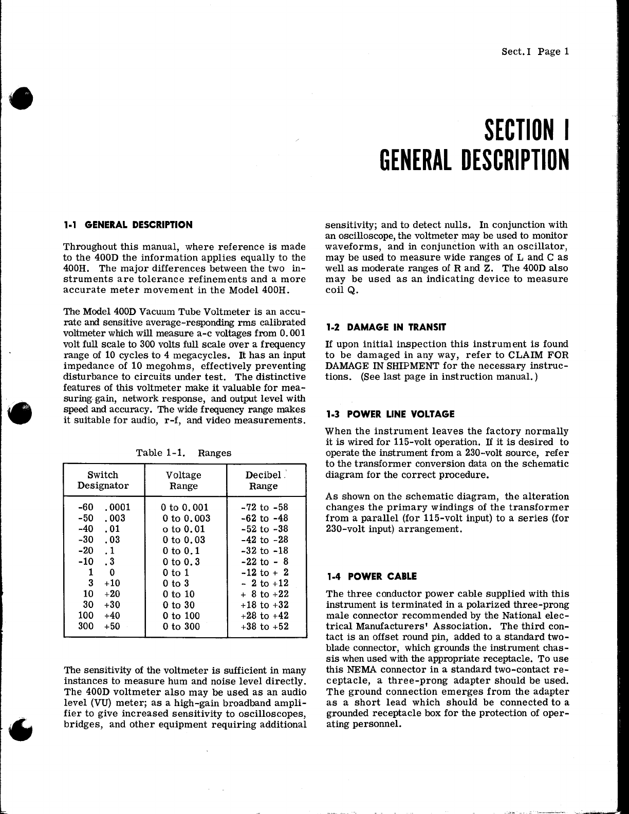
range are shown in Table 1-1.
INPUT AND OUTPUT TERMINALSPUT are con-
nected to the input circuit of the instrument. The
two binding posts designated OUTPUT are the output
terminals for the amplifier. The lower binding post
in each pair, designated G is connected to tfie Chas-
sis. The binding posts will accommodate either a
banana plug or wire, and are so arranged that any
double banana plug with a 3/4 Lnch spacing may be
used.
CAUTION
The maximum voltage (the sum of the d-c voltage
and a-c peak voltage) applied to the input terminals
of the Model 400D Vacuum Tube voltmeter must not
erSggd_qlqJglts. Higher voltages will break down
the capacitors in the input system of the instru-
ment.
METER
mA ,i00-D meter is a d-c milliammeter calibrated to
indicate the rms value of a sine wave.
FUSE
if[E-fuseholder, Iocated on the back of the instru-
ment, contains a l-ampere cartridge fuse which is
OPERATII{G I}ISTRUGTIO}IS
in the power supply input circuit. Replacement fuses
must be of the rtSlo-Blot' type as specifiedin the
Table of Replaceable Parts.
NOTE
When the power transformer is connected for 230-
volt operation, use a l/Z-ampere " Slo-Blo, car-
tridge fuse.
2.2 OPERATION
When the Model 400D is received from the factory,
the meter pointer should indicate zero before the
instrument is turned ol. If it does not, adjust the
pointer to zero as explained under Section IV,
paragraph 4-2. After the instrument is turned on,
the meter pointer may show an indication of as much
as two scale divisions, principally on the one-milli-
volt range. This effect is normal and does not im-
pair the accuracy of the instrument.
On the lowest three ranges of the instrument the
high input impedance coupled with the gain of the
amplifi.er causes the meter needle to be forced
against the right-hand stop of the meter when the
input terminals are unshielded. This condition is
normal and is caused by stray voltages in the vicinity
of the instrument.
If measurements are made from a high-impedance
source, hum pick-up can affect the meter indication
because of the high impedance of both the source and
the Model 400D. Shielded leads wiil reduce pick-up,
although they wiil cause an increase in the capacity
shunted across the source, with the possibility of
excessive circuit loading.
a. VoltageMeasurements
rct ptugged intoapower
source of specified voltage and frequency, and the
toggle switch at ON, allow the instrument about
five minutes to reach a state of stable operation.
o