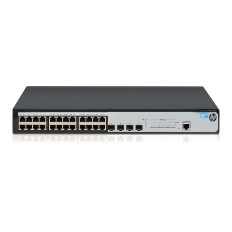
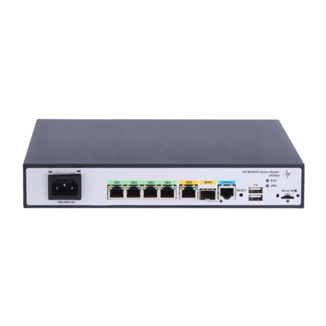
HP A6602 User manual

HP A6602 Router
Installation Manual

About This Manual
Organization
HP A6602 Routers Installation Manual is organized as follows:
Chapter Contents
1 Router Overview Briefly introduces the product specifications, as well as
the features and applications of the HP A6602.
2 Preparing for Installation
Describes the requirements on installation site, the
safety recommendations before and during installation,
and the required tools.
3 Installing the Router
Introduces how to install the A6602, as well as how to
connect the power cable, console cable, AUX port
cable, Ethernet cable, interface card and interface
module cable.
4 Starting and Configuring the Router
Helps you get familiar with the basic knowledge of how
to boot and configure the HP A6602, including device
startup, power-on, and initialization of system files, and
so on.
5 Maintaining Software
Introduces how to maintain the software of the HP
A6602, including upgrading the software and updating
the configuration files.
6 Maintaining Hardware Introduces how to maintain the hardware of the HP
A6602.
7 Troubleshooting
Describes some problems that may occur during
installation and startup of the router and how to solve
them.
Conventions
The manual uses the following conventions:
Command conventions
Convention Description
Boldface The keywords of a command line are in Boldface.
italic Command arguments are in italic.
[ ] Items (keywords or arguments) in square brackets [ ] are optional.
{ x | y | ... } Alternative items are grouped in braces and separated by vertical bars. One is
selected.
[ x | y | ... ] Optional alternative items are grouped in square brackets and separated by
vertical bars. One or none is selected.

Convention Description
{ x | y | ... } * Alternative items are grouped in braces and separated by vertical bars. A
minimum of one or a maximum of all can be selected.
[ x | y | ... ] * Optional alternative items are grouped in square brackets and separated by
vertical bars. Many or none can be selected.
&<1-n> The argument(s) before the ampersand (&) sign can be entered 1 to n times.
# A line starting with the # sign is comments.
GUI conventions
Convention Description
Boldface Window names, button names, field names, and menu items are in Boldface.
For example, the New User window appears; click OK.
>Multi-level menus are separated by angle brackets. For example, File >
Create >Folder.
Convention Description
< > Button names are inside angle brackets. For example, click <OK>.
[ ] Window names, menu items, data table and field names are inside square
brackets. For example, pop up the [New User] window.
/Multi-level menus are separated by forward slashes. For example,
[File/Create/Folder].
Symbols
Convention Description
Means reader be extremely careful. Improper operation may cause bodily
injury.
Means reader be careful. Improper operation may cause data loss or damage
to equipment.
Means an action or information that needs special attention to ensure
successful configuration or good performance.
Means a complementary description.
Means techniques helpful for you to make configuration with ease.
Related Documentation
In addition to this manual, each HP SR6600 Routers documentation set includes the following:
Manual Description
HP A6600 Routers User Manual It is a guide for the user to perform the operations
correctly. It is organized into the parts of access, IP
services, IP routing, MPLS, VPN, QoS, security,

Manual Description
system, multicast, and OAA.
It also gives the user a detailed description of the
operating commands. It is organized into the parts of
access, IP services, IP routing, MPLS, VPN, QoS,
security, system, multicast, and OAA, as well as a
command index.
HP A6600 Routers Interface Card and Interface
Module Manual
This manual introduces all kinds of interface modules
that SR6600 routers support, the means of
connection the interface cables and the interface
module purchase guide.
Low-End and Mid-Range Series Routers Cable
Manual This manual introduces all cable pinouts available
with low-end and mid-range series routers.
Environmental Protection
This product has been designed to comply with the requirements on environmental
protection. For the proper storage, use and disposal of this product, national laws and
regulations must be observed.

1
Router Overview
Introduction
The HP A6602
router (hereinafter referred to as the
gateway router developed by
networks. The A6602
uses an advanced high
data forwarding and service processing engine and also has a built
hardware encryption engine. The
runs on HP
proprietary Comware V5 platform. Abundant optional modules are available so that
the A6602
can have a higher processing capability and can support more flexible configuration
to fully meet the req
uirements of enterprise networks.
The A6602
can serve as not only a gateway connecting an enterprise network to a WAN/MAN,
but also a service gateway (for example, VPN gateway, NAT gateway, or IPSec gateway) in an
enterprise network. In addition, the
provide full network solutions for governments and departments in electric power, finance, tax,
public security, railway, and education, as well as medium
complianc
e with the active national and international standards ensures the interoperability with
products of other manufacturers at different layers.
The A6602 supports high-
speed interface modules (HIMs) and provides a bus processing
capability of up to 10 Gbps,
which can meet the high
In addition, the A6602
is compatible with some multi
HP
AR/MSR series routers to guarantee the smooth upgrade from narrowband access to
broadband access. The
A6602
the intermixing of a HIM and a MIM.
Physical Description
Front Panel
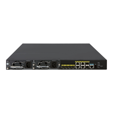
Figure 1-1
Front panel of the
(1) AC power socket (100 VAC to 240 VAC; 50 Hz or 60 Hz; 2.5 A)
(2) AC
power switch (ON/OFF)
(4) CF card slot (CF CARD)
(6) RPS LED (RPS)
(8) RESET button (RESET)
(10) Slot 1 LED (SLOT1)
(12) USB 1 LED (USB)
(14) USB interface 0
(16) AUX port (AUX)
Router Overview
router (hereinafter referred to as the
A6602) is a high-
performance service
gateway router developed by
Hewlett Packard (hereinafter referred to as
HP
uses an advanced high
-performance multi-
core microprocessor as the
data forwarding and service processing engine and also has a built
-
in 10 Gbps wire
hardware encryption engine. The
A6602 adopts an industry-
leading hardware architecture and
proprietary Comware V5 platform. Abundant optional modules are available so that
can have a higher processing capability and can support more flexible configuration
uirements of enterprise networks.
can serve as not only a gateway connecting an enterprise network to a WAN/MAN,
but also a service gateway (for example, VPN gateway, NAT gateway, or IPSec gateway) in an
enterprise network. In addition, the
A6602 can work together with other HP
network devices to
provide full network solutions for governments and departments in electric power, finance, tax,
public security, railway, and education, as well as medium
- and large-
sized enterprises. The full
e with the active national and international standards ensures the interoperability with
products of other manufacturers at different layers.
speed interface modules (HIMs) and provides a bus processing
which can meet the high
-
speed performance requirements of users.
is compatible with some multi
-
functional interface modules (MIMs) of the
AR/MSR series routers to guarantee the smooth upgrade from narrowband access to
A6602
supports two HIMs or two MIMs at the same time, or supports
the intermixing of a HIM and a MIM.
Physical Description
Front panel of the
A6602
(1) AC power socket (100 VAC to 240 VAC; 50 Hz or 60 Hz; 2.5 A)
power switch (ON/OFF)
(3) RPS socket (RPS)
(4) CF card slot (CF CARD)
(5) CF card LED (CF)
(7) Slot 2 LED (SLOT2)
(8) RESET button (RESET)
(9) System LED (SYS)
(10) Slot 1 LED (SLOT1)
(11) AC power LED (PWR)
(13) USB interface 1
(15) Console port (CONSOLE)
performance service
HP
) for enterprise
core microprocessor as the
in 10 Gbps wire
-speed
leading hardware architecture and
proprietary Comware V5 platform. Abundant optional modules are available so that
can have a higher processing capability and can support more flexible configuration
can serve as not only a gateway connecting an enterprise network to a WAN/MAN,
but also a service gateway (for example, VPN gateway, NAT gateway, or IPSec gateway) in an
network devices to
provide full network solutions for governments and departments in electric power, finance, tax,
sized enterprises. The full
e with the active national and international standards ensures the interoperability with
speed interface modules (HIMs) and provides a bus processing
speed performance requirements of users.
functional interface modules (MIMs) of the
AR/MSR series routers to guarantee the smooth upgrade from narrowband access to
supports two HIMs or two MIMs at the same time, or supports
(3) RPS socket (RPS)
(5) CF card LED (CF)
(7) Slot 2 LED (SLOT2)
(9) System LED (SYS)
(11) AC power LED (PWR)
(15) Console port (CONSOLE)
Rear Panel
Figure 1-2 Rear panel of the
A6602
(1) Grounding screw and grounding sign
(2) 10/100/1000 Mbps electrical Ethernet interface 1
(3) 1000 Mbps optical
Ethernet interface 1
(4) 1000 Mbps optical Ethernet interface LED (SFP3)
(5) 1000 Mbps optical Ethernet interface LED (SFP2)
(6) 1000 Mbps optical Ethernet interface LED (SFP1)
(7) 1000 Mbps optical Ethernet interface LED (SFP0)
(8) 10/100/1000 Mbps e
(9) 1000 Mbps optical Ethernet interface 3
(11) HIM/MIM slot (2)
(13) 10/100/1000 Mbps electrical Ethernet interface 2
(14) 1000 Mbps optical Ethernet interf
(15) 10/100/1000 Mbps electrical Ethernet interface 0
Technical Specifications
Processor and Storages
Table 1-1
Processor and storages of the
Item
Processor
Flash
Memory type and size
Compact flash (CF) card
A6602
(1) Grounding screw and grounding sign
(2) 10/100/1000 Mbps electrical Ethernet interface 1
Ethernet interface 1
(4) 1000 Mbps optical Ethernet interface LED (SFP3)
(5) 1000 Mbps optical Ethernet interface LED (SFP2)
(6) 1000 Mbps optical Ethernet interface LED (SFP1)
(7) 1000 Mbps optical Ethernet interface LED (SFP0)
(8) 10/100/1000 Mbps e
lectrical Ethernet interface 3
(9) 1000 Mbps optical Ethernet interface 3
(10) HIM/MIM slot 1
(12) 1000 Mbps optical Ethernet interface 2
(13) 10/100/1000 Mbps electrical Ethernet interface 2
(14) 1000 Mbps optical Ethernet interf
ace 0
(15) 10/100/1000 Mbps electrical Ethernet interface 0
Technical Specifications
Processor and Storages
Processor and storages of the
A6602
Specification
Multi-core MIPS processor 1 GHz
4 MB
DDR2 SDRAM
2 GB (default)
4 GB (maximum)
(Memory modules must be used in pairs, and don’t support 1.5G, 3G
or 3.5G)
Compact flash (CF) card
256 MB by default for the built-
in CF card; 256 MB, 512 MB, or 1 GB
for an optional external CF card(CF cards less th
supported)
(12) 1000 Mbps optical Ethernet interface 2
Specification
(Memory modules must be used in pairs, and don’t support 1.5G, 3G
in CF card; 256 MB, 512 MB, or 1 GB
for an optional external CF card(CF cards less th
an 256 MB are not

Dimensions and Weight
Table 1-2 Dimensions and weight
Item Specification
Dimensions without feet and rack-mounting ears (H ×
W × D) 44 × 442 × 460 mm (1.73 × 17.40 × 18.11 in.)
Weight 7.5 kg (16.53 lb)
Fixed Interfaces and Slots
Table 1-3 Fixed interfaces and slots
Item Specification
Console port 1 (9600 bps to 115200 bps, 9600 bps by default)
AUX port 1 (9600 bps to 115200 bps, 9600 bps by default)
USB interfaces 2 USB 0: Type A connector, operating in the host mode
USB 1: Type B connector, operating in the device mode
Combo interfaces
Four electrical
Ethernet interfaces:
GE 0 to GE 3
10 Mbps, half duplex/full duplex
100 Mbps, half duplex/full duplex
1000 Mbps, full duplex
Four optical Ethernet
interfaces: SFP 0 to
SFP 3 1000 Mbps, full duplex
CF card slot 1
The optional CF cards supported by the A6602 are available in
three sizes:
256 MB
512 MB
1 GB
Interface module
slots 2HIM/MIM intermixing is supported.
Two HIMs or two MIMs can be inserted at the same time.
An electrical Ethernet interface and its corresponding optical Ethernet interface form a Combo
interface.
The electrical Ethernet interface and optical Ethernet interface of a Combo interface cannot
work simultaneously.
For a Combo interface, the default operating interface is the optical Ethernet interface. You can
switch between the optical Ethernet interface and the electrical Ethernet interface by using the
combo enable {copper |fiber } command in interface view.
For details about the combo enable {copper |fiber } command, refer to HP SR6600 Routers
User Manual.

AC Power Input
Table 1-4 AC power specifications
Item Specification
Rated voltage range 100 VAC to 240 VAC; 50 Hz or 60 Hz
Maximum input current 2.5 A
Maximum power 150 W
Power Consumption Range
Table 1-5 Power consumption range of the entire system
Item Specification
Power consumption range 64 W to 111 W
Operating Environment
Table 1-6 Operating environment
Item Specification
Operating temperature 0°C to 45°C (32°F to 113°F)
Operating humidity 10% to 95%, noncondensing
Operating altitude – 60 m to 3 km (–196.85 ft. to +1.87 miles)
Components
Processor and Storages
Processor
The A6602 uses an RMI XLR732 1GHz multi-core microprocessor as its data forwarding and
service processing engine.
Flash
The Flash size is 4 MB, of which 1 MB is used for storing the boot file— the BootWare program
and the remaining space for backing up the BootWare program and storing important system
parameters.
Memory module
The memory module is used for storing the data during system operation and caching the data
during data forwarding. The default memory size of the A6602 is one GB and the maximum
memory size is two GB. The A6602 provides two memory slots and you must insert two memory
modules of the same type and the same size.
The memory modules for the A6602 have two sizes:
DDR2 SDRAM-512MB
DDR2 SDRAM-1GB
CF card
1) Introduction
A compact flash (CF) card is used for storing logs, host files, and configuration files.

The A6602
is equipped with a built
the A6602
provides an external CF card slot to expand the local storage spac
inserted into the external CF card slot is identified with
The optional CF cards supported by the
256 MB
512 MB
1 GB
Use CF cards provided by
HP
2) CF card and slot
Figure 1-3 CF card and slot
(1) Eject button
3) CF card LED
For the description of the CF card LED, see
The CF card is hot-
swappable. When the router is performing a file read or write operation on
the CF card (the CF card LED is blinking), do not eject the CF card. Otherwise, the file sy
on the CF card will be damaged.
Panel LEDs
Front Panel LEDs
Figure 1-4 Front panel LEDs
Table 1-7
Description of front panel LEDs
LED
PWR (green)
Off
On
RPS
Off
is equipped with a built
-
in 256 MB CF card, which is identified with
provides an external CF card slot to expand the local storage spac
inserted into the external CF card slot is identified with
cfb0.
The optional CF cards supported by the
A6602 are available in three sizes:
HP
only. The device may be incompatible with other CF cards.
(2) CF card slot
(3) CF card LED (CF)
For the description of the CF card LED, see
Table 1-7 on page 1-6.
swappable. When the router is performing a file read or write operation on
the CF card (the CF card LED is blinking), do not eject the CF card. Otherwise, the file sy
on the CF card will be damaged.
Description of front panel LEDs
Status
Meaning
Off
The power module does not supply power to the system.
On
The power module su
pplies power to the system normally.
Off
There is no RPS DC power input.
in 256 MB CF card, which is identified with
cfa0. In addition,
provides an external CF card slot to expand the local storage spac
e. A CF card
only. The device may be incompatible with other CF cards.
(3) CF card LED (CF)
swappable. When the router is performing a file read or write operation on
the CF card (the CF card LED is blinking), do not eject the CF card. Otherwise, the file sy
stem
Meaning
The power module does not supply power to the system.
pplies power to the system normally.
There is no RPS DC power input.

LED
(yellow/green)
Solid green
Solid yellow
SLOT1 (green)
Off
On
SLOT2 (green)
Off
On
SYS (green)
Off
Slow blinking (1 Hz)
Fast blinking (8 Hz)
CF (green)
Of
f
On
Blinking
USB1 (green)
Off
On
Blinking
Rear Panel LEDs
Figure 1-5 Rear panel LEDs
(1) 10/100/1000 Mbps electrical Ethernet interface LED (GE0)
(2) 10/100/1000 Mbps electrical Ethernet interface LED (GE1)
(3) 1000 Mbps optical Ethernet interface LED (SFP3)
(4) 1000 Mbps optical Ethernet inter
(5) 1000 Mbps optical Ethernet interface LED (SFP1)
(6) 1000 Mbps optical Ethernet interface LED (SFP0)
(7) 10/100/1000 Mbps electrical Ethernet interface LED (GE2)
(8) 10/100/1000 Mbps electrical Ethernet interface LED (GE3)
Status
Meaning
Solid green
Both AC power input and RPS DC input are normal.
Solid yellow
AC power input is abnormal, and RPS DC input is normal.
Off
No inter
face module is in slot 1 or the interface module is faulty.
On
An interface module is in slot 1 and operates normally.
Off
No interface module is in slot 2 or the interface module is faulty.
On
An interface module is in slot 2 and oper
Off
The system is powered off or the board is faulty.
Slow blinking (1 Hz)
The board operates normally as configured.
Fast blinking (8 Hz)
Software is being loaded or the board does not start working
yet.
f
No CF card is in position or the CF card cannot be identified.
On
A CF card is in position and the host has detected the CF card.
You can remove the card in this state.
Blinking
The system is accessing the CF card. Do not remove the card
in this state.
Off
No host is connected to the USB interface.
On
A host is connected to the USB interface. You can unplug the
USB cable in this state.
Blinking
Data is being transmitted or received. Do not unplug the USB
cable in this state.
(1) 10/100/1000 Mbps electrical Ethernet interface LED (GE0)
(2) 10/100/1000 Mbps electrical Ethernet interface LED (GE1)
(3) 1000 Mbps optical Ethernet interface LED (SFP3)
(4) 1000 Mbps optical Ethernet inter
face LED (SFP2)
(5) 1000 Mbps optical Ethernet interface LED (SFP1)
(6) 1000 Mbps optical Ethernet interface LED (SFP0)
(7) 10/100/1000 Mbps electrical Ethernet interface LED (GE2)
(8) 10/100/1000 Mbps electrical Ethernet interface LED (GE3)
Meaning
Both AC power input and RPS DC input are normal.
AC power input is abnormal, and RPS DC input is normal.
face module is in slot 1 or the interface module is faulty.
An interface module is in slot 1 and operates normally.
No interface module is in slot 2 or the interface module is faulty.
An interface module is in slot 2 and oper
ates normally.
The system is powered off or the board is faulty.
The board operates normally as configured.
Software is being loaded or the board does not start working
No CF card is in position or the CF card cannot be identified.
A CF card is in position and the host has detected the CF card.
You can remove the card in this state.
The system is accessing the CF card. Do not remove the card
No host is connected to the USB interface.
A host is connected to the USB interface. You can unplug the
Data is being transmitted or received. Do not unplug the USB

Table 1-8 Description of rear panel LEDs
LED Status Meaning
GE0 to GE3
(yellow/green)
Off No link is present.
Solid green A 1000 Mbps link is present.
Blinking green Data is being received or transmitted at a rate of 1000 Mbps.
Solid yellow A 10/100 Mbps link is present.
Blinking yellow Data is being received or transmitted at a rate of 10/100 Mbps.
SFP0 to SFP3
(yellow/green)
Off No link is present.
Solid green A 1000 Mbps link is present.
Blinking green Data is being received or transmitted at a rate of 1000 Mbps.
Solid yellow The system fails to detect the SFP port.
Fixed Interfaces
Table 1-9 Fixed interfaces
Fixed interface Specification
Console 1
AUX 1
USB interfaces 2 USB 0: Type A connector, operating in the host mode
USB 1: Type B connector, operating in the device mode
CF card slot 1
The optional CF cards supported by the A6602 are available in three
sizes:
256 MB
512 MB
1 GB
Combo interfaces 4
Four electrical Ethernet interfaces: GE0 to GE3
Four optical Ethernet interfaces: SFP0 to SFP3
For a Combo interface, the default operating interface is the optical
Ethernet interface.
For a Combo interface, you can use either the electrical Ethernet
interface or the optical Ethernet interface at a point of time. You can use
the combo enable {copper |fiber } command in interface view to
switch between the optical and electrical Ethernet interfaces.
Console port
1) Introduction
The A6602 provides an RS-232 asynchronous serial console port that can be connected to a
computer for system debugging, configuration, maintenance, management, and host software
loading.
2) Technical specifications for the console port
Table 1-10 Technical specifications for the console port
Item Specification
Connector RJ-45

Item
Compliant standard
Baud rate
Transmission distance
Services
3) Console cable
The console cable is an 8-
core shielded cable. The R
connected to the console port on the router, and the DB
the serial port on a configuration terminal.
Figure 1-6
illustrates the console cable.
Figure 1-6 Console cable
Table 1-11
Console cable conn
RJ-45 pin
1
2
3
4
5
6
7
8
For the connection of the console cable, refer to “Connecting the Console Cable” in Chapter 3
“Installing the Router”.
AUX port
1) Introduction
The AUX port is an RS-
232 asynchronous serial interface used for remote configuration or
dialup backup. You need to connect the local modem to the remote modem through PSTN and
then to the remote device for
management. In the event that the console port fails, the AUX port can be connected to a
Specification
RS-232
9600 bps to 115200 bps
9600 bps (default)
≤15 m (49.21 ft.)
Connection to an ASCII terminal
Connection to the serial interface of a local PC to run the terminal emulation
program
Command line interface (CLI)
core shielded cable. The R
J-
45 connector at one end of the cable is
connected to the console port on the router, and the DB
-
9 female connector at the other end to
the serial port on a configuration terminal.
illustrates the console cable.
Console cable conn
ector pinouts
Signal direction DB-9 pin
8
6
2
1
— 5
3
4
7
For the connection of the console cable, refer to “Connecting the Console Cable” in Chapter 3
232 asynchronous serial interface used for remote configuration or
dialup backup. You need to connect the local modem to the remote modem through PSTN and
then to the remote device for
remote system debugging, configuration, maintenance, and
management. In the event that the console port fails, the AUX port can be connected to a
Specification
Connection to the serial interface of a local PC to run the terminal emulation
45 connector at one end of the cable is
9 female connector at the other end to
Signal
CTS
DSR
RXD
DCD
GND
TXD
DTR
RTS
For the connection of the console cable, refer to “Connecting the Console Cable” in Chapter 3
232 asynchronous serial interface used for remote configuration or
dialup backup. You need to connect the local modem to the remote modem through PSTN and
remote system debugging, configuration, maintenance, and
management. In the event that the console port fails, the AUX port can be connected to a

terminal as a backup port of the console port. For the method of connecting a terminal through
the AUX port, r
efer to “Using the AUX Port as Backup Console Port” in Chapter 7
“Troubleshooting”.
2)
Technical specifications for the AUX port
Table 1-12
Technical specifications for the AUX port
Item
Connector
Compliant standard
Baud rate
Services
3) AUX cable
The AUX cable is an 8-
core shielded cable. At one end o
which is connected to the AUX port on the router. At the other end are a DB
and a DB-
25 (male) connector, of which you can select one to connect the serial port on a
modem as needed.
Figure 1-7 AUX cable
Table 1-13
AUX cable connector pinouts
RJ-45 pin
1
2
3
4
5
—
6
7
8
For the connection of the AUX cable, refer to “Connecting the AUX Port to a Modem” in Chapter
3 “Installing the Router”.
terminal as a backup port of the console port. For the method of connecting a terminal through
efer to “Using the AUX Port as Backup Console Port” in Chapter 7
Technical specifications for the AUX port
Specification
RJ-45
RS-232
9600 bps to 115200 bps
9600 bps (default)
Used to connect the serial port of a remote PC through a pair of modems to
establish a dial-up connection with the PC
core shielded cable. At one end o
f the cable is an RJ
which is connected to the AUX port on the router. At the other end are a DB
-
9 (male) connector
25 (male) connector, of which you can select one to connect the serial port on a
AUX cable connector pinouts
Signal direction DB-25 pin DB-
9 pin
4 7
20 4
2 3
8 1
—
7 5
3 2
6 6
5 8
For the connection of the AUX cable, refer to “Connecting the AUX Port to a Modem” in Chapter
terminal as a backup port of the console port. For the method of connecting a terminal through
efer to “Using the AUX Port as Backup Console Port” in Chapter 7
Used to connect the serial port of a remote PC through a pair of modems to
f the cable is an RJ
-45 connector,
9 (male) connector
25 (male) connector, of which you can select one to connect the serial port on a
9 pin
Signal
RTS
DTR
TXD
DCD
GND
RXD
DSR
CTS
For the connection of the AUX cable, refer to “Connecting the AUX Port to a Modem” in Chapter

Combo interfaces
1) Introduction
The A6602 provides four Combo interfaces. Each Combo interface consists of an electrical
Ethernet interface and an optical Ethernet interface, but either the electrical Ethernet interface
or the optical Ethernet interface can operate at one time.
Each fixed electrical Ethernet interface supports 10/100/1000 Mbps auto-sensing. For the rate
and duplex for the electrical Ethernet interfaces, see Table 1-14.
Table 1-14 Rate and duplex for the electrical Ethernet interfaces
Rate Duplex
10 Mbps (auto-sensing) Half/full-duplex auto-negotiation
100 Mbps (auto-sensing) Half/full-duplex auto-negotiation
1000 Mbps (auto-sensing) Full-duplex
The electrical Ethernet interface LEDs are above the RJ-45 ports. The LEDs in triangle and
inverted triangle indicate the status of the lower and upper electrical Ethernet interfaces,
respectively.
Each optical Ethernet interface supports a rate of 1000 Mbps in full-duplex mode. The optical
Ethernet interface LEDs are in the middle of the four Combo interfaces and use separate LEDs
to indicate the status of the corresponding SFP interfaces.
Figure 1-8 Combo interfaces on the rear panel
(1) 10/100/1000 Mbps electrical Ethernet interface (GE1)
(2) 1000 Mbps optical Ethernet interface (SFP1)
(3) 10/100/1000 Mbps electrical Ethernet interface (GE3)
(4) 1000 Mbps optical Ethernet interface (SFP3)
(5) 1000 Mbps optical Ethernet interface (SFP2)
(6) 10/100/1000 Mbps electrical Ethernet interface (GE2)
(7) 1000 Mbps optical Ethernet interface (SFP0)
(8) 10/100/1000 Mbps electrical Ethernet interface (GE0)
For a Combo interface, the default operating interface is the Ethernet electrical interface.
For a Combo interface, you can use either the electrical Ethernet interface or the optical
Ethernet interface. You can use the combo enable {copper |fiber } command in interface
view to switch between the optical and electrical Ethernet interfaces.
For details about the combo enable {copper |fiber } command, refer to HP SR6600 Routers
User Manual.
2) Technical specifications for Combo interface
Technical specifications for electrical Ethernet interfaces

Table 1-15 Technical specifications for electrical Ethernet interfaces
Item Specification
Connector RJ-45
Interface Automatic MDI/MDI-X
Frame format Ethernet_II
Ethernet_SNAP
Rate and duplex
10 Mbps Half/full-duplex auto-negotiation
100 Mbps Half/full-duplex auto-negotiation
1000 Mbps Full-duplex
The media dependent interface (MDI) standard is typically used on the Ethernet interface of
network adapters. The media dependent interface crossover (MDI-X) standard is typically used
on hubs or LAN switches.
When 10/100 Mbps and half duplex/full duplex are specified for an electrical Ethernet interface,
the electrical Ethernet interface operates in the forced mode. When 1000Mbps is specified or
the rate and the duplex mode are not simultaneously specified for an electrical Ethernet
interface, the electrical Ethernet interface operates in the auto-negotiation mode.
An electrical Ethernet interface supports automatic MDI/MDI-X in both the forced mode and the
auto-negotiation mode; namely, it supports both straight-through and crossover cables.
Technical specifications for optical Ethernet interfaces
Table 1-16 Technical specifications for 1000 Mbps optical Ethernet interfaces
Item Specification
Connector SFP/LC
Compliant standard 802.3, 802.3u, and 802.3ab
Optical
transmit
power
Type
Short-haul
multi-mode
optical module
(850 nm)
Medium-haul
single-mode
optical module
(1310 nm)
Long-haul
optical module
(1310 nm)
Long-haul
optical
module
(1550 nm)
Ultra-long
haul optical
module
Min –9.5 dBm –9 dBm –2 dBm –4 dBm –4 dBm
Max 0 dBm –3 dBm 5 dBm 1 dBm 2 dBm
Receiving sensitivity –17 dBm –20 dBm –23 dBm –21 dBm –22 dBm
Central wavelength 850 nm 1310 nm 1310 nm 1550 nm 1550 nm
Fiber type 62.5/125 μm
multi-mode
fiber
9/125 μm
single-mode
fiber
9/125 μm
single-mode
fiber
9/125 μm
single-mode
fiber
9/125 μm
single-mode
fiber
Maximum
transmission distance 0.55 km (0.34
miles) 10 km (6.21
miles) 40 km (24.86
miles) 40 km (24.86
miles) 70 km (43.50
miles)
Duplex 1000 Mbps in full-duplex
3) RJ-45 connector

The 10/100/1000 Mbps electrical Ethernet interfaces of the
support automatic MDI/MDI-
X. Category
Figure 1-9
shows the appearance of an RJ
Figure 1-9 RJ-45 connector
4) LC connector
Optical fiber connectors are indispensable passive components in optical fiber communication
sy
stems. Their application enables the removable connection between optical channels, which
makes the optical system debugging and maintenance more convenient and the transit
dispatching of the system more flexible.
Some optical fiber connector types are as
LC: square optical fiber connector of the push
SC: standard optical fiber connector
FC: round optical fiber connector with screw thread
ST: round plug-
in optical fiber connector
MT-
RJ: square optical transceiver connector
Currently, the HP
SR6600 routers support only the LC
Figure 1-10 LC connector
Before using an optical fiber to connect a network device, make sure that the optical fiber
conn
ector matches the optical module.
Before connecting a fiber, make sure that the optical power at the receiving end does not
exceed the upper threshold of the optical receive power of the optical module. Otherwise, the
optical module may be dama
ged.
5)
Cable connecting a 1000 Mbps electrical Ethernet interface
Usually, you can use a category
interface to an Ethernet.
Figure 1
Figure 1-11 Ethernet cable
Ethernet cables
fall into the following two categories:
The 10/100/1000 Mbps electrical Ethernet interfaces of the
A6602 use RJ-
45 connectors and
X. Category
-
5 twisted pair cables are used for RJ
shows the appearance of an RJ
-45 connector.
Optical fiber connectors are indispensable passive components in optical fiber communication
stems. Their application enables the removable connection between optical channels, which
makes the optical system debugging and maintenance more convenient and the transit
dispatching of the system more flexible.
Some optical fiber connector types are as
follows:
LC: square optical fiber connector of the push
-pull snap-in type
SC: standard optical fiber connector
FC: round optical fiber connector with screw thread
in optical fiber connector
RJ: square optical transceiver connector
SR6600 routers support only the LC
-type connectors.
Before using an optical fiber to connect a network device, make sure that the optical fiber
ector matches the optical module.
Before connecting a fiber, make sure that the optical power at the receiving end does not
exceed the upper threshold of the optical receive power of the optical module. Otherwise, the
ged.
Cable connecting a 1000 Mbps electrical Ethernet interface
Usually, you can use a category
-
5 twisted pair cable to connect a 1000 Mbps electrical Ethernet
Figure 1
-11 shows an Ethernet cable.
fall into the following two categories:
45 connectors and
5 twisted pair cables are used for RJ
-45 connectors.
Optical fiber connectors are indispensable passive components in optical fiber communication
stems. Their application enables the removable connection between optical channels, which
makes the optical system debugging and maintenance more convenient and the transit
Before using an optical fiber to connect a network device, make sure that the optical fiber
Before connecting a fiber, make sure that the optical power at the receiving end does not
exceed the upper threshold of the optical receive power of the optical module. Otherwise, the
5 twisted pair cable to connect a 1000 Mbps electrical Ethernet

Standard cable: Also called straight-through cable. At both ends of a standard cable, wires are
crimped in the RJ-45 connectors in the same sequence. A straight-through cable is used to
connect a terminal (for example, PC or router) to a hub or LAN Switch. The cables delivered
with the A6602 are straight-through cables.
Crossover cable: At both ends of a crossover cable, wires are crimped in the RJ-45 connectors
in different sequences. A crossover cable is used to connect a terminal (for example, a PC or
router) to another terminal. You can make crossover cables by yourself as needed.
Table 1-17 Straight-through cable pinouts
RJ-45 pin Signal Category-5
twisted pair Signal direction RJ-45 pin
1 Tx+ White (Orange) 1
2 Tx– Orange 2
3 Rx+ White (Green) 3
4 — Blue — 4
5 — White (Blue) — 5
6 Rx– Green 6
7 — White (Brown) — 7
8 — Brown — 8
Table 1-18 Crossover cable pinouts
RJ-45 pin Signal direction Category-5
twisted pair Signal direction RJ-45 pin
1 Tx+ White (Orange) 3
2 Tx– Orange 6
3 Rx+ White (Green) 1
4 — Blue — 4
5 — White (Blue) — 5
6 Rx– Green 2
7 — White (Brown) — 7
8 — Brown — 8
You can refer to the table above when distinguishing between or preparing these two types of
Ethernet cables.
When preparing Ethernet cables, please follow the chromatogram given in the table to arrange
the wires. Otherwise communication quality will be affected even if the devices at both ends are
connected.
When preparing Ethernet cables, use shielded cables preferentially for electromagnetic
compatibility (EMC).
6) Fiber connecting a 1000 Mbps optical Ethernet interface
You can use a single-mode or multi-mode optical fiber to connect a 1000 Mbps optical Ethernet
interface to an Ethernet. You can select proper fibers for the installed 1000Base-FX SFP
transceiver (GE SFP for short). Since the optical interfaces on these SFP transceivers use LC

optical connectors, you must use fibers with LC connectors. All SFP transceiver are hot-
swappable.
No SFP module is shipped with the A6602 unless ordered.
Use only the SFP modules provided by HP. The A6602 cannot identify SFP modules from other
manufacturers.
For the connection of electrical Ethernet interface or optical Ethernet interface cables, refer to
“Connecting Ethernet Cables” in Chapter 3 “Installing the Router”.
USB Interfaces
The universal serial bus (USB) interfaces can connect multiple types of devices and provide a
higher data transfer rate than common parallel interfaces and serial interfaces.
The A6602 fully supports USB 1.1. The USB interfaces on the router provide important storage
and security functions. For example, they provide large Flash memory space for application
programs, configuration files, and security VPN certificates to establish secure VPN connections
and secure the delivery of router configuration files.
In addition, USB interfaces provide a backup CF card mechanism to make file backup and
restoration very convenient and reliable.
Figure 1-12 USB Interfaces
(1) USB interface 0 (2) USB interface 1 (3) USB interface 1 LED
USB0
USB interface 0 on the A6602 is a USB 1.1-compliant type-A interface. USB interface 0 can be
connected to an external USB storage device to expand the router’s space for storing files and
logs and facilitate file transfer.
Insert and remove a USB storage device correctly. Otherwise, the software, hardware and file
system of the USB storage device may get damaged.
After you insert a USB storage device and information is displayed on the terminal, prompting
the USB storage device is inserted into the A6602, the LED on the USB storage device will be
on.
When the LED on the USB storage device is blinking, do not remove the USB storage device.
Before removing the USB storage device, execute the umount usba0: command in user view
to unmount the USB storage device. If information is displayed on the terminal, prompting the
USB storage device is successfully unmounted, you can remove the USB storage device. After
the USB storage device is removed, information will also be displayed on the terminal, showing
the USB storage device has been removed.
The A6602 only supports the USB storage devices provided by HP and may be incompatible
with those from other manufacturers.
For details about the umount command, refer to HP SR6600 Routers User Manual.

USB1
USB interface 1 on the A6602 is a USB 1.1-compliant type-B interface. USB interface 1 can be
connected to a terminal or computer through a standard cable. After the interface is enabled,
the built-in CF card of the A6602 is recognized as an external storage device by the computer
and you can access the internal CF card quickly and perform file operations on it.
Table 1-19 describes the USB interface 1 LED.
Table 1-19 Description of USB interface 1 LED
Status Meaning
Solid green A link is present.
Blinking green Data is being received or transmitted. In this state, do not unplug the USB cable.
Interface Modules
The A6602 provides two HIM/MIM slots, in which you can insert a HIM and a MIM, or two HIMs,
or two MIMs. HIMs and MIMs are hot-swappable.
For the installation and removal of HIMs and MIMs, refer to Chapter 6 “Maintaining Hardware”.
“Hot-swapping” a module refers to first using the remove slot number command to stop the
module and then pulling it out manually, or inserting the module into its slot without powering off
the device.
RESET Button
To reset the router, you can press the RESET button.
The SYS LED goes off when the router is reset, flashes fast (at 8 Hz) when it is booting, and
flashes slowly (at 1 Hz) when it operates normally.
If you perform no save operation before resetting the router, the current system configuration
will not be saved after the router is reset.
Never press the RESET button when the router is booting (when the SYS LED is blinking fast).
Otherwise, the file system of the router may be damaged.
AC Power Input
Table 1-20 lists the AC input power specifications for the A6602.
Table 1-20 AC input power specifications for the A6602
Item Specification
Rated voltage range 100 VAC to 240 VAC; 50 Hz or 60 Hz
Maximum input current 2.5 A
Maximum power 150 W

Clock
The A6602 router is designed with a clock module that provides the system time. You can set
the system time on the command line interface.
Use the clock datetime time date command in user view to set the system date and time. For
the description of the clock datetime command, refer to HP SR6600 Routers User Manual.
When a power failure occurs to the router, the clock module can continue working to ensure the
system time is correct next time the router boots. With the router powered off, the clock module
can work for at least 10 years.
When the router is powered on, pay attention to the following points:
Never replace the clock module battery.
The system time gets lost once the battery of the clock module is removed, and you need to set
the system time again on the command line interface. However, the system time will still get lost
after the router is powered off.
You can use the clock datetime,clock summer-time one-off (or clock summer-time
repeating), and clock time zone commands to set the system date and time. For details about
these commands, refer to HP SR6600 Routers User Manual.
RPS (Optional)
The redundancy power supply (RPS) can provide power supply to maintain the normal system
operation for a short period when the system power supply fails.
The RPS uses a control pin to control its output status. When the system power supply fails, it
sends a LOW signal to the control pin of the RPS. Upon receiving the LOW signal, the RPS
switches to the output status within 10 ms and starts to supply power to the router.
The A6602 supports AC power input and RPS input. They can guarantee the router to continue
working when one power supply fails, thus providing high reliability.
Table 1-21 Specifications for the RPS of the A6602
Specification Value
Rated output voltage 12 V
Maximum output current 14 A
Maximum output power 168 W
The RPS is an optional component not shipped with the router.
For the RPS installation, refer to “Connecting the RPS DC Power Cable” in Chapter 3 “Installing
the Router”.
Port Lightning Arrester (Optional)
Before connecting an outdoor Ethernet cable to an Ethernet port, you can install a port lightning
arrester to protect the router against lightning strokes.
The following port lightning arrester can be installed on the A6602. The specifications for the
port lightning arrester are as follows:
Port protective unit–single port, maximum discharge current (8/20μs waveform): 5 kA, output
voltage (10/700μs waveform): core-core < 40 V, core-ground < 600 V.
Table of contents
Other HP Network Router manuals

HP
HP StorageWorks e1200-160 User manual

HP
HP StorageWorks N1200-320 User manual

HP
HP SCSI-Fibre Channel Router User manual

HP
HP HP 2530 User manual

HP
HP 6125XLG User manual

HP
HP 7000dl Series User manual

HP
HP A58x0AF Bck(pwr)-Frt(ports) Assembly instructions

HP
HP MSR SERIES User manual

HP
HP MSR930 Series Assembly instructions

HP
HP A-MSR900 Series User manual

HP
HP A5120 EI Series Installation manual

HP
HP 5920 User manual

HP
HP FlexNetwork MSR2003 User manual

HP
HP 5500 si series User manual

HP
HP VSR1000 User manual

HP
HP MSR20-20 User manual

HP
HP HP ProCurve Series 6600 User manual

HP
HP 7000dl Series User instructions

HP
HP 2100 ER User manual

HP
HP A-MSR20 How to use