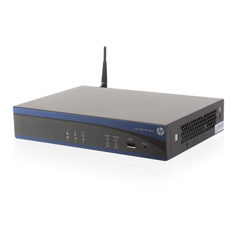
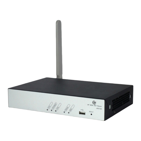
HP MSR SERIES User manual

HP MSR Router Series
High Availability
Configuration Guide(V7)
Part number: 5998-7716b
Software version: CMW710-R0304
Document version: 6PW104-20150914

i
Legal and notice information
© Copyright 2015 Hewlett-Packard Development Company, L.P.
No part of this documentation may be reproduced or transmitted in any form or by any means without
prior written consent of Hewlett-Packard Development Company, L.P.
The information contained herein is subject to change without notice.
HEWLETT-PACKARD COMPANY MAKES NO WARRANTY OF ANY KIND WITH REGARD TO THIS
MATERIAL, INCLUDING, BUT NOT LIMITED TO, THE IMPLIED WARRANTIES OF MERCHANTABILITY
AND FITNESS FOR A PARTICULAR PURPOSE. Hewlett-Packard shall not be liable for errors contained
herein or for incidental or consequential damages in connection with the furnishing, performance, or use
of this material.
The only warranties for HP products and services are set forth in the express warranty statements
accompanying such products and services. Nothing herein should be construed as constituting an
additional warranty. HP shall not be liable for technical or editorial errors or omissions contained herein.

i
Contents
Configuring interface backup ····································································································································· 1
Overview············································································································································································1
Compatible interfaces ··············································································································································1
Backup modes ··························································································································································1
Configuration restrictions and guidelines·······················································································································3
Interface backup configuration task list ··························································································································4
Configuring strict active/standby interface backup ······································································································4
Explicitly specifying backup interfaces without traffic thresholds········································································4
Using interface backup with the Track module ·····································································································5
Configuring load-shared interface backup·····················································································································6
Displaying and maintaining interface backup···············································································································6
Interface backup configuration examples ······················································································································7
Strict active/standby interface backup configuration example···········································································7
Strict active/standby interface backup with the Track module configuration example····································8
Load-shared interface backup configuration example ······················································································ 10
Configuring VRRP·······················································································································································12
Overview········································································································································································· 12
VRRP standard mode ····················································································································································· 13
Router priority in a VRRP group ··························································································································· 13
Preemption ····························································································································································· 13
Authentication method ·········································································································································· 14
VRRP timers ···························································································································································· 14
Master election ······················································································································································ 15
VRRP tracking························································································································································· 15
VRRP application ··················································································································································· 15
VRRP load balancing mode ·········································································································································· 17
Virtual MAC address assignment ························································································································ 17
Virtual forwarder ··················································································································································· 19
Protocols and standards ················································································································································ 21
Configuring IPv4 VRRP ·················································································································································· 21
IPv4 VRRP configuration task list·························································································································· 21
Specifying an IPv4 VRRP operating mode·········································································································· 22
Specifying the IPv4 VRRP version ························································································································ 22
Creating a VRRP group and assigning a virtual IP address ············································································· 23
Configuring the router priority, preemptive mode, and tracking function ······················································ 24
Specifying an IPv4 VRRP control VLAN ·············································································································· 24
Configuring IPv4 VRRP packet attributes ············································································································ 26
Configuring VF tracking········································································································································ 27
Enabling SNMP notifications for VRRP················································································································ 28
Disabling an IPv4 VRRP group····························································································································· 28
Displaying and maintaining IPv4 VRRP··············································································································· 28
Configuring IPv6 VRRP ·················································································································································· 29
IPv6 VRRP configuration task list·························································································································· 29
Specifying an IPv6 VRRP operating mode·········································································································· 29
Creating a VRRP group and assigning a virtual IPv6 address ········································································· 30
Configuring the router priority, preemptive mode, and tracking function ······················································ 31
Specifying an IPv6 VRRP control VLAN ·············································································································· 31
Configuring VF tracking········································································································································ 33

ii
Configuring IPv6 VRRP packet attributes ············································································································ 34
Disabling an IPv6 VRRP group····························································································································· 34
Displaying and maintaining IPv6 VRRP··············································································································· 35
IPv4 VRRP configuration examples······························································································································· 35
Single VRRP group configuration example········································································································· 35
Multiple VRRP groups configuration example ···································································································· 38
VRRP load balancing configuration example····································································································· 40
IPv6 VRRP configuration examples······························································································································· 48
Single VRRP group configuration example········································································································· 48
Multiple VRRP groups configuration example ···································································································· 51
VRRP load balancing configuration example····································································································· 54
Troubleshooting VRRP···················································································································································· 62
An error prompt is displayed ······························································································································· 62
Multiple masters appear in a VRRP group·········································································································· 63
Fast VRRP state flapping ······································································································································· 63
Configuring BFD·························································································································································64
Overview········································································································································································· 64
BFD session establishment ···································································································································· 64
BFD session modes and operating modes·········································································································· 64
Supported features ················································································································································ 65
Protocols and standards ······································································································································· 66
Configuring BFD basic functions ·································································································································· 66
Configuring echo packet mode ··························································································································· 66
Configuring control packet mode························································································································ 67
Configuring a BFD template································································································································· 69
Enabling SNMP notifications ······························································································································· 69
Displaying and maintaining BFD·································································································································· 70
Configuring Track ······················································································································································71
Overview········································································································································································· 71
Collaboration fundamentals································································································································· 71
Collaboration application example····················································································································· 72
Track configuration task list··········································································································································· 72
Associating the Track module with a detection module····························································································· 73
Associating Track with NQA ······························································································································· 73
Associating Track with BFD·································································································································· 73
Associating Track with interface management··································································································· 74
Associating the Track module with an application module······················································································· 75
Associating Track with VRRP································································································································ 75
Associating Track with static routing··················································································································· 76
Associating Track with PBR ·································································································································· 77
Displaying and maintaining track entries···················································································································· 80
Track configuration examples······································································································································· 80
VRRP-Track-NQA collaboration configuration example···················································································· 80
Configuring BFD for a VRRP backup to monitor the master·············································································· 84
Configuring BFD for the VRRP master to monitor the uplink ············································································· 86
Static routing-Track-NQA collaboration configuration example ······································································ 90
Static routing-Track-BFD collaboration configuration example········································································· 94
VRRP-Track-interface management collaboration configuration example ······················································· 97
Configuring process placement ····························································································································· 101
Overview·······································································································································································101
Process··································································································································································101
1:N process redundancy····································································································································101
Process placement policy and optimization ·····································································································101

iii
Command and hardware compatibility ····················································································································103
Configuration restrictions and guidelines··················································································································103
Process placement configuration task list ··················································································································103
Configuring process placement policy ······················································································································104
Configuring a location affinity ···························································································································104
Configuring a location type affinity···················································································································104
Configuring a process affinity····························································································································105
Configuring a self affinity···································································································································105
Optimizing process placement ···································································································································106
Displaying process placement ····································································································································106
Support and other resources ·································································································································· 107
Contacting HP ······························································································································································107
Subscription service ············································································································································107
Related information······················································································································································107
Documents····························································································································································107
Websites·······························································································································································107
Conventions ··································································································································································108
Index ········································································································································································ 110

1
Configuring interface backup
Overview
Interface backup enables you to configure multiple backup interfaces for a Layer 3 interface to increase
link availability. When the primary interface fails or is overloaded, its backup interfaces can take over or
participate in traffic forwarding.
Compatible interfaces
The interface backup feature is configurable for the interfaces in Table 1.
Table 1 Interfaces that support interface backup
Cate
g
or
y
Interfaces Remarks
Ethernet Layer 3 Ethernet interfaces/subinterfaces
Layer 3 VE interfaces N/A
WAN
AM interfaces
ATM interfaces
ISDN BRI interfaces
POS interfaces
Serial interfaces (asynchronous, synchronous)
The AM interfaces can only work as
backup interfaces. All the other
interfaces can work as both primary
and backup interfaces.
An ISDN BRI interface can work as
the primary interface only when it is
configured to provide leased line
services.
An asynchronous serial interface
cannot work as the primary
interface if DDR is configured on it.
Others
AUX ports
Dialer interfaces
MP-group interfaces
Tunnel interfaces
A dialer interface can be used as
the primary interface only when it is
a PPPoE client in permanent session
mode.
Backup modes
The primary interface and its backup interfaces can operate in strict active/standby mode or load
sharing mode.
•Strict active/standby mode—Only one interface transmits traffic. All the other interfaces are in
STANDBY state.
•Load sharing mode—Backup interfaces participate in traffic forwarding when the amount of traffic
on the primary interface reaches the upper threshold. They are activated and deactivated
depending on the amount of traffic.

2
In strict active/standby mode, traffic loss occurs when the active interface is overloaded. Load sharing
mode improves link efficiency and reduces the risk of packet loss.
Strict active/standby mode
In strict active/standby mode, the primary interface always has higher priority than all backup interfaces.
•When the primary interface is operating correctly, all traffic is transmitted through the primary
interface.
•When the primary interface fails, the highest-priority backup interface takes over. If the
highest-priority backup interface also fails, the second highest-priority backup interface takes over,
and so forth.
NOTE:
If two backup interfaces have the same priority, the one configured first has preference.
An active backup interface is always preempted by the primary interface. However, a higher-priority
backup interface cannot preempt a lower-priority backup interface that has taken over the primary
interface.
•The primary interface takes over when it recovers from a failure condition.
•The higher-priority backup interface cannot take over when it recovers from a failure condition while
the primary interface is still down.
As shown in Figure 1, GigabitEthernet 2/0/1 on Router A is the primary interface. GigabitEthernet
2/0/2 (with a priority of 30) and GigabitEthernet 2/0/3 (with a priority of 20) are its backup interfaces.
•When GigabitEthernet 2/0/1 is operating correctly, all traffic is transmitted through
GigabitEthernet 2/0/1.
•When GigabitEthernet 2/0/1 fails, GigabitEthernet 2/0/2 takes over because it has higher
priority than GigabitEthernet 2/0/3. If GigabitEthernet 2/0/2 also fails, GigabitEthernet 2/0/3
takes over.
•When GigabitEthernet 2/0/1 is recovered, it preempts the active backup interface because it is the
primary interface. If GigabitEthernet 2/0/2 is recovered while GigabitEthernet 2/0/1 is still down,
GigabitEthernet 2/0/2 cannot preempt GigabitEthernet 2/0/3 to forward traffic.
Figure 1 Strict active/backup mode
Load sharing mode
In load sharing mode, the backup interfaces are activated to transmit traffic depending on the traffic load
on the primary interface.
•When the amount of traffic on the primary interface exceeds the upper threshold, the backup
interfaces are activated in descending order of priority. This action continues until the traffic drops
below the upper threshold.

3
•When the amount of traffic on the primary interface decreases below the lower threshold, the
backup interfaces are deactivated in ascending order of priority. This action continues until the
amount of traffic exceeds the lower threshold.
•When the primary interface fails (in DOWN state), the strict active/standby mode applies. Only
one backup interface can forward traffic.
The upper and lower thresholds are user configurable.
NOTE:
•"Traffic" on an interface refers to the amount of incoming or outgoing traffic, whichever is higher.
•If two backup interfaces have the same priority, the one configured first has preference.
As shown in Figure 2, GigabitEthernet 2/0/1 on Router A is the primary interface. GigabitEthernet
2/0/2 (with a priority of 30) and GigabitEthernet 2/0/3 (with a priority of 20) are its backup interfaces.
•When the amount of traffic on GigabitEthernet 2/0/1 exceeds the upper threshold,
GigabitEthernet 2/0/2 is activated, because it has higher priority than GigabitEthernet 2/0/3. If
the amount of traffic on GigabitEthernet 2/0/1 still exceeds the upper threshold, GigabitEthernet
2/0/3 is activated.
•When the amount of traffic on GigabitEthernet 2/0/1 decreases below the lower threshold,
GigabitEthernet 2/0/3 is first deactivated, because its priority is lower than GigabitEthernet
2/0/2. If the amount of traffic on GigabitEthernet 2/0/1 is still below the lower threshold,
GigabitEthernet 2/0/2 is deactivated.
Figure 2 Load sharing mode
Configuration restrictions and guidelines
When you configure interface backup, follow these restrictions and guidelines:
•The device supports up to 10 primary interfaces.
•An interface can be configured as a backup only for one interface.
•An interface cannot be both a primary and backup interface.
•For correct traffic forwarding, make sure the primary and backup interfaces have routes to the
destination network.

4
Interface backup configuration task list
Task Remarks
Configuring strict active/standby interface backup:
•(Method 1.) Explicitly specifying backup interfaces
without traffic thresholds
•(Method 2.) Using interface backup with the Track
module
You cannot use these two methods at the same time
for a primary interface and its backup interfaces.
Use method 1 if you want to monitor the interface
state of the primary interface for a switchover to
occur.
Use method 2 if you want to monitor any other state,
such as the link state of the primary interface.
Configuring load-shared interface backup
A primary interface and its backup interfaces
operate in load sharing mode after you specify the
traffic thresholds on the primary interface.
This method cannot be used with the other two
methods at the same time for an interface.
Configuring strict active/standby interface backup
You can use one of the following methods to configure strict active/standby interface backup:
•Explicitly specify backup interfaces for a primary interface. If this method is used, interface backup
changes the state of the backup interface in response to the interface state change of the primary
interface.
•Use interface backup with the Track module. If this method is used, interface backup uses a track
entry to monitor the link state of the primary interface. Interface backup changes the state of a
backup interface in response to the link state change of the primary interface.
Explicitly specifying backup interfaces without traffic thresholds
For the primary and backup interfaces to operate in strict active/standby mode, do not specify the traffic
thresholds on the primary interface. If the traffic thresholds are configured, the interfaces will operate in
load sharing mode.
You can assign priority to backup interfaces. When the primary interface fails, the backup interfaces are
activated in descending order of priority, with the highest-priority interface activated first. If two backup
interfaces have the same priority, the one configured first has preference.
To prevent link flapping from causing frequent interface switchovers, you can configure the following
switchover delay timers:
•Up delay timer—Number of seconds that the primary or backup interface must wait before it can
come up.
•Down delay timer—Number of seconds that the active primary or backup interface must wait
before it is set to down state.
When the link of the active interface fails, the interface state does not change immediately. Instead, a
down delay timer starts. If the link recovers before the timer expires, the interface state does not change.
If the link is still down when the timer expires, the interface state changes to down.
To configure strict active/standby interface backup for a primary interface:

5
Ste
p
Command
Remarks
1. Enter system view. system-view N/A
2. Enter interface view. interface interface-type
interface-number This interface must be the primary interface.
3. Specify a backup
interface.
backup interface interface-type
interface-number [ priority ]
By default, an interface does not have any
backup interfaces.
Repeat this command to specify up to three
backup interfaces for the interface.
4. Set the switchover delay
timers.
backup timer delay up-delay
down-delay
By default, the up and down delay timers are
both 5 seconds.
Using interface backup with the Track module
To use interface backup with the Track module to provide strict active/standby backup for a primary
interface:
•Configure a track entry to monitor state information of the primary interface. For example, monitor
its link state.
•Associate the track entry with a backup interface.
Interface backup changes the state of the backup interface in response to the track entry state, as shown
in Table 2.
Table 2 Action on the backup interface in response to the track entry state change
Track entr
y
state
State of the monitored
p
rimar
y
link
Action on the backu
p
interface
Positive The primary link is operating correctly. Places the backup interface in
STANDBY state.
Negative The primary link has failed. Activates the backup interface to take
over.
NotReady
The primary link is not monitored.
This situation occurs when the track module or
the monitoring module is not ready, for
example, because the Track module is
restarting or the monitoring settings are
incomplete. In this situation, interface backup
cannot obtain information about the primary
link from the track module.
•If the track entry state stays in
NotReady state after it is created,
interface backup does not change
the state of the backup interface.
•If the track entry state changes to
NotReady from Positive or
Negative, the backup interface
changes back to the forwarding
state before it was used for
interface backup.
For more information about configuring a track entry, see "Configuring Track."
When you associate a backup interface with a track entry, follow these guidelines:
•You can associate an interface with only one track entry.
•You can create the associated track entry before or after the association. The association takes
effect after the track entry is created.
•To maintain performance, limit the number of associations to 64.

6
To associate Track with an interface:
Ste
p
Command
Remarks
1. Enter system view. system-view N/A
2. Enter interface view. interface interface-type
interface-number
This interface must be the interface
you are using as a backup.
3. Associate the interface with a
track entry. backup track track-entry-number By default, an interface is not
associated with a track entry.
Configuring load-shared interface backup
To implement load-balanced interface backup, you must configure the traffic thresholds on the primary
interface. Interface backup regularly compares the amount of traffic on the primary interface with the
thresholds to determine whether to activate or deactivate a backup interface. The traffic polling interval
is user configurable.
You can assign priority to backup interfaces.
•When the amount of traffic on the primary interface exceeds the upper threshold, the backup
interfaces are activated in descending order of priority.
•When the amount of traffic on the primary interface decreases below the lower threshold, the
backup interfaces are deactivated in ascending order of priority.
If two backup interfaces have the same priority, the one configured first has preference.
If a traffic flow has a fast forwarding entry, all packets of the flow will be forwarded out of the outgoing
interface in the entry. The packets of the flow will not be distributed between interfaces when the upper
threshold is reached. For more information about fast forwarding, see Layer 3—IP Services Configuration
Guide.
To configure load-shared backup for an interface:
Ste
p
Command
Remarks
1. Enter system view. system-view N/A
2. Enter interface view. interface interface-type
interface-number
You must enter the view of the
primary interface.
3. Configure a backup interface
for the interface.
backup interface interface-type
interface-number [ priority ]
By default, an interface does not
have any backup interfaces.
Repeat this command to specify up
to three backup interfaces.
4. Set backup load sharing
thresholds.
backup threshold upper-threshold
lower-threshold
By default, no traffic thresholds are
configured.
5. Set the traffic polling interval. backup timer flow-check interval The default interval is 30 seconds.
Displaying and maintaining interface backup
Execute display commands in any view.

7
Task Command
Display traffic statistics for load-shared interfaces. display interface-backup statistics
Display the status of primary and backup interfaces. display interface-backup state
Interface backup configuration examples
Strict active/standby interface backup configuration example
Network requirements
As shown in Figure 3:
•Specify GigabitEthernet 2/0/2 and GigabitEthernet 2/0/3 on Router A to back up
GigabitEthernet 2/0/1.
•Assign GigabitEthernet 2/0/2 a higher priority than GigabitEthernet 2/0/3.
•Set the up and down delay timers to 10 seconds for the backup interfaces.
Figure 3 Network diagram
Configuration procedure
1. Assign IP addresses to interfaces, as shown in Figure 3. (Details not shown.)
2. Configure routes:
# On Router A, configure static routes to 192.168.2.0/24 through the primary and backup
interfaces.
<RouterA> system-view
[RouterA] ip route-static 192.168.2.0 24 gigabitethernet 2/0/1
[RouterA] ip route-static 192.168.2.0 24 gigabitethernet 2/0/2
[RouterA] ip route-static 192.168.2.0 24 gigabitethernet 2/0/3
# On Router B, configure static routes to 192.168.1.0/24.
<RouterB> system-view
[RouterB] ip route-static 192.168.1.0 24 gigabitethernet 2/0/1
[RouterB] ip route-static 192.168.1.0 24 gigabitethernet 2/0/2
[RouterB] ip route-static 192.168.1.0 24 gigabitethernet 2/0/3
3. On Router A, configure backup interfaces and switchover delays:

8
# Specify GigabitEthernet 2/0/2 and GigabitEthernet 2/0/3 to back up GigabitEthernet 2/0/1,
and assign them a priority of 30 and 20, respectively.
[RouterA] interface gigabitethernet 2/0/1
[RouterA-GigabitEthernet2/0/1] backup interface gigabitethernet 2/0/2 30
[RouterA-GigabitEthernet2/0/1] backup interface gigabitethernet 2/0/3 20
# Set both up and down delay timers to 10 seconds.
[RouterA-GigabitEthernet2/0/1] backup timer delay 10 10
Verifying the configuration
# Display states of the primary and backup interfaces.
[RouterA-GigabitEthernet2/0/1] display interface-backup state
Interface: GE2/0/1
UpDelay: 10 s
DownDelay: 10 s
State: UP
Backup interfaces:
GE2/0/2 Priority: 30 State: STANDBY
GE2/0/3 Priority: 20 State: STANDBY
The output shows that GigabitEthernet 2/0/1 is in UP state and the two backup interfaces are in
STANDBY state.
# Shut down the primary interface GigabitEthernet 2/0/1.
[RouterA-GigabitEthernet2/0/1] shutdown
# Verify that the backup interface GigabitEthernet 2/0/2 comes up 10 seconds after the primary
interface goes down.
[RouterA-GigabitEthernet2/0/1] display interface-backup state
Interface: GE2/0/1
UpDelay: 10 s
DownDelay: 10 s
State: DOWN
Backup interfaces:
GE2/0/2 Priority: 30 State: UP
GE2/0/3 Priority: 20 State: STANDBY
Strict active/standby interface backup with the Track module
configuration example
Network requirements
As shown in Figure 4, configure a track entry to monitor the link state of GigabitEthernet 2/0/1. When
the link of GigabitEthernet 2/0/1 fails, the backup interface GigabitEthernet 2/0/2 comes up to take
over.

9
Figure 4 Network diagram
Configuration procedure
1. Assign IP addresses to interfaces, as shown in Figure 4. (Details not shown.)
2. Configure routes:
# On Router A, configure static routes to 192.168.2.0/24 through the primary and backup
interfaces.
<RouterA> system-view
[RouterA] ip route-static 192.168.2.0 24 gigabitethernet 2/0/1
[RouterA] ip route-static 192.168.2.0 24 gigabitethernet 2/0/2
# On Router B, configure static routes to 192.168.1.0/24.
<RouterB> system-view
[RouterB] ip route-static 192.168.1.0 24 gigabitethernet 2/0/1
[RouterB] ip route-static 192.168.1.0 24 gigabitethernet 2/0/2
3. On Router A, configure track settings:
# Configure track entry 1 to monitor the link state of GigabitEthernet 2/0/1.
[RouterA] track 1 interface gigabitethernet 2/0/1
# Associate track entry 1 with the backup interface GigabitEthernet 2/0/2.
[RouterA] interface gigabitethernet 2/0/2
[RouterA-GigabitEthernet2/0/2] backup track 1
[RouterA-GigabitEthernet2/0/2] quit
Verifying the configuration
# Verify that the backup interface GigabitEthernet 2/0/2 is in STANDBY state while the primary link is
operating correctly.
[RouterA] display interface-backup state
IB Track Information:
GE2/0/2 Track: 1 State: STANDBY
# Shut down the primary interface GigabitEthernet 2/0/1.
[RouterA] interface gigabitethernet 2/0/1
[RouterA-GigabitEthernet2/0/1] shutdown
# Verify that the backup interface GigabitEthernet 2/0/2 comes up after the primary link goes down.
[RouterA-GigabitEthernet2/0/1] display interface-backup state
IB Track Information:
GE2/0/2 Track: 1 State: UP

10
Load-shared interface backup configuration example
Network requirements
As shown in Figure 5:
•Configure GigabitEthernet 2/0/2 and GigabitEthernet 2/0/3 on Router A to back up the primary
interface GigabitEthernet 2/0/1.
•Assign GigabitEthernet 2/0/2 higher priority than GigabitEthernet 2/0/3.
•On the primary interface:
{Specify the interface bandwidth used for traffic load calculation.
{Set the upper and lower thresholds to 80 and 20, respectively.
Figure 5 Network diagram
Configuration procedure
1. Assign IP addresses to interfaces, as shown in Figure 5. (Details not shown.)
2. Configure routes:
# On Router A, configure routes to 192.168.2.0/24 through the primary and backup interfaces.
<RouterA> system-view
[RouterA] ip route-static 192.168.2.0 24 gigabitethernet 2/0/1
[RouterA] ip route-static 192.168.2.0 24 gigabitethernet 2/0/2
[RouterA] ip route-static 192.168.2.0 24 gigabitethernet 2/0/3
# On Router B, configure routes to 192.168.1.0/24.
<RouterB> system-view
[RouterB] ip route-static 192.168.1.0 24 gigabitethernet 2/0/1
[RouterB] ip route-static 192.168.1.0 24 gigabitethernet 2/0/2
[RouterB] ip route-static 192.168.1.0 24 gigabitethernet 2/0/3
3. On Router A, configure backup interfaces and traffic thresholds:
# Specify GigabitEthernet 2/0/2 and GigabitEthernet 2/0/3 to back up GigabitEthernet 2/0/1,
and assign them with a priority of 30 and 20, respectively.
[RouterA] interface gigabitethernet 2/0/1
[RouterA-GigabitEthernet2/0/1] backup interface gigabitethernet 2/0/2 30
[RouterA-GigabitEthernet2/0/1] backup interface gigabitethernet 2/0/3 20
# Set the expected bandwidth to 10000 kbps on the primary interface.
[RouterA-GigabitEthernet2/0/1] bandwidth 10000

11
# Set the upper and lower thresholds to 80 and 20, respectively.
[RouterA-GigabitEthernet2/0/1] backup threshold 80 20
Verifying the configuration
# Display traffic statistics for load-shared interfaces.
[RouterA-GigabitEthernet2/0/1] display interface-backup statistics
Interface: GigabitEthernet2/0/1
Statistics interval: 30 s
Bandwidth: 10000000 bps
PrimaryTotalIn: 102 bytes
PrimaryTotalOut: 108 bytes
PrimaryIntervalIn: 102 bytes
PrimaryIntervalOut: 108 bytes
Primary used bandwidth: 28 bps
TotalIn: 102 bytes
TotalOut: 108 bytes
TotalIntervalIn: 102 bytes
TotalIntervalOut: 108 bytes
Total used bandwidth: 28 bps
The output shows that the upper traffic threshold has not been exceeded. All traffic is transmitted through
the primary interface GigabitEthernet 2/0/1.
# Verify that both backup interfaces are in STANDBY state because the upper threshold has not been
exceeded.
[RouterA-GigabitEthernet2/0/1] display interface-backup state
Interface: GE2/0/1
UpDelay: 0 s
DownDelay: 0 s
Upper threshold: 80
Lower threshold: 20
State: UP
Backup interfaces:
GE2/0/2 Priority: 30 State: STANDBY
GE2/0/3 Priority: 20 State: STANDBY
# Increase the incoming or outgoing traffic rate to be higher than 8000 kbps (80% of the specified
bandwidth) on the primary interface. (Details not shown.)
# Verify that the backup interface GigabitEthernet 2/0/2 comes up to participate in traffic forwarding,
because it has higher priority than GigabitEthernet 2/0/3.
[RouterA-GigabitEthernet2/0/1] display interface-backup state
Interface: GE2/0/1
UpDelay: 0 s
DownDelay: 0 s
Upper threshold: 80
Lower threshold: 20
State: UP
Backup interfaces:
GE2/0/2 Priority: 30 State: UP
GE2/0/3 Priority: 20 State: STANDBY

12
Configuring VRRP
Overview
Typically, you can configure a default gateway for every host on a LAN. All packets destined for other
networks are sent through the default gateway. As shown in Figure 6, when the default gateway fails, no
hosts can communicate with external networks.
Figure 6 LAN networking
Using a default gateway facilitates your configuration but requires high availability. Using more egress
gateways improves link availability but introduces the problem of routing among the egresses.
Virtual Router Redundancy Protocol (VRRP) is designed to address this issue. VRRP adds a group of
network gateways to a VRRP group called a virtual router. A VRRP group comprises one master and
multiple backups, but has only one virtual IP address. The hosts on the subnet only need to configure this
virtual IP address as their default network gateway for communicating with external networks.
The virtual IP address of the virtual router can be either of the following IP addresses:
•Unused IP address on the subnet where the VRRP group resides.
•IP address of an interface on a router in the VRRP group.
In the latter case, the router is called the IP address owner. A VRRP group can have only one IP address
owner.
VRRP avoids single points of failure and simplifies the configuration on hosts. When the master in the
VRRP group on a multicast or broadcast LAN (for example, an Ethernet network) fails, another router in
the VRRP group takes over. The switchover is complete without causing dynamic route recalculation, route
re-discovery, gateway reconfiguration on the hosts, or traffic interruption.
VRRP operates in either of the following modes:
•Standard mode—Implemented based on RFCs. For more information, see "VRRP standard mode."
•Load balancing mode—Extends the VRRP standard mode to distribute load across VRRP group
members. For more information, see "VRRP load balancing mode."

13
VRRP has two versions: VRRPv2 and VRRPv3. VRRPv2 supports IPv4 VRRP. VRRPv3 supports IPv4 VRRP
and IPv6 VRRP.
VRRP standard mode
In VRRP standard mode, only the master in the VRRP group can provide gateway service. When the
master fails, the backup routers elect a new master to take over for nonstop gateway service.
Figure 7 VRRP networking
As shown in Figure 7, Router A, Router B, and Router C form a virtual router, which has its own IP address.
Hosts on the subnet use the virtual router as the default gateway.
The router with the highest priority among the three routers is elected as the master, and the other two are
backups.
Router priority in a VRRP group
VRRP determines the role (master or backup) of each router in a VRRP group by priority. A router with
higher priority is more likely to become the master.
The VRRP priority is in the range of 0 to 255, and a greater number represents a higher priority. Priorities
1 to 254 are configurable. Priority 0 is reserved for special uses, and priority 255 is for the IP address
owner. The IP address owner in a VRRP group always has a running priority of 255 and acts as the
master as long as it operates correctly.
Preemption
A router in a VRRP group operates in either non-preemptive mode or preemptive mode.
•Non-preemptive mode—The master router acts as the master as long as it operates correctly, even
if a backup router is later assigned a higher priority. Non-preemptive mode helps avoid frequent
switchover between the master and backup routers.
•Preemptive mode—A backup starts a new master election and takes over as master when it detects
that it has a higher priority than the current master. Preemptive mode makes sure the router with the
highest priority in a VRRP group always acts as the master.

14
Authentication method
To avoid attacks from unauthorized users, VRRP member routers add authentication keys in VRRP packets
to authenticate one another. VRRP provides the following authentication methods:
•Simple authentication
The sender fills an authentication key into the VRRP packet, and the receiver compares the received
authentication key with its local authentication key. If the two authentication keys match, the
received VRRP packet is legitimate. Otherwise, the received packet is illegitimate and gets
discarded.
•MD5 authentication
The sender computes a digest for the VRRP packet by using the authentication key and MD5
algorithm, and saves the result to the packet. The receiver performs the same operation with the
authentication key and MD5 algorithm, and compares the result with the content in the
authentication header. If the results match, the received VRRP packet is legitimate. Otherwise, the
received packet is illegitimate and gets discarded.
On a secure network, you can choose to not authenticate VRRP packets.
NOTE:
IPv4 VRRPv3 and IPv6 VRRPv3 do not support VRRP packet authentication.
VRRP timers
Skew_Time
Skew_Time helps avoid the situation that multiple backups in a VRRP group become the master when the
master in the VRRP group fails.
Skew_Time is not configurable; its value depends on the VRRP version.
•In VRRPv2 (described in RFC 3768), Skew_Time is (256 – Router priority)/256.
•In VRRPv3 (described in RFC 5798), Skew_Time is ((256 – Router priority) × VRRP advertisement
interval)/256.
VRRP advertisement interval
The master in a VRRP group periodically sends VRRP advertisements to declare its presence.
You can configure the interval at which the master sends VRRP advertisements. If a backup does not
receive any VRRP advertisement when the timer (3 × VRRP advertisement interval + Skew_Time) expires,
it takes over as the master.
VRRP preemption delay timer
You can configure the VRRP preemption delay timer for the following purposes:
•Avoid frequent state changes among members in a VRRP group.
•Provide the backups with enough time to collect information (such as routing information).
In preempt mode, a backup does not immediately become the master after it receives an advertisement
with lower priority than the local priority. Instead, it waits for a period of time (preemption delay time +
Skew_Time) before taking over as the master.

15
Master election
Routers in a VRRP group determine their roles by priority. When a router joins a VRRP group, it has a
backup role. The router role changes according to the following situations:
•If the backup does not receive any VRRP advertisement when the timer (3 × advertisement interval
+ Skew_Time) expires, it becomes the master.
•If the backup receives a VRRP advertisement with the same or greater priority within the timer (3 ×
advertisement interval + Skew_Time), it remains a backup.
•If the backup receives a VRRP advertisement with a smaller priority within the timer (3 ×
advertisement interval + Skew_Time), the following results apply:
{It remains a backup when operating in non-preemptive mode.
{It becomes the master when operating in preemptive mode.
The elected master starts a VRRP advertisement interval to periodically send VRRP advertisements to
notify the backups that it is operating correctly. Each of the backups starts a timer to wait for
advertisements from the master.
After a backup receives a VRRP advertisement, it compares only the priority in the packet with its own
priority.
When multiple routers in a VRRP group declare that they are the master because of network problems,
the one with the highest priority becomes the master. If two routers have the same priority, the one with
the highest IP address becomes the master.
VRRP tracking
To enable VRRP tracking, configure the routers in the VRRP group to operate in preemptive mode first.
This configuration ensures that only the router with the highest priority operates as the master.
The VRRP tracking function uses network quality analyzer (NQA) or bidirectional forwarding detection
(BFD) to monitor the state of the master or the upstream link. The collaboration between VRRP and NQA
or BFD through a track entry implements the following functions:
•Monitors the upstream link and changes the priority of the router according to the state of the link.
If the upstream link fails, the hosts on the subnet cannot access external networks through the router
and the state of the track entry becomes Negative. The priority of the master decreases by a
specified value, and a router with a higher priority in the VRRP group becomes the master. The
switchover ensures uninterrupted communication between the hosts on the subnet and external
networks.
•Monitors the state of the master on the backups. When the master fails, a backup immediately takes
over to ensure uninterrupted communication.
When the track entry changes from Negative to Positive or Notready, the router automatically restores its
priority. For more information about track entries, see "Configuring Track."
VRRP application
Master/backup
In master/backup mode, only the master forwards packets, as shown in Figure 8. When the master fails,
a new master is elected from among the backups. This mode requires only one VRRP group, and each
router in the group has a different priority. The one with the highest priority becomes the master.
Other manuals for MSR SERIES
14
Table of contents
Other HP Network Router manuals

HP
HP StorageWorks M2402 User manual

HP
HP FlexNetwork 6600 User manual

HP
HP MSR SERIES Installation manual

HP
HP MSR SERIES Installation manual

HP
HP Pavilion a6600 User manual

HP
HP PS110 User manual

HP
HP N1200 - StorageWorks Network Storage Router User manual

HP
HP 6125XLG User manual

HP
HP A-MSR30-16 Installation instructions

HP
HP A6616 User manual