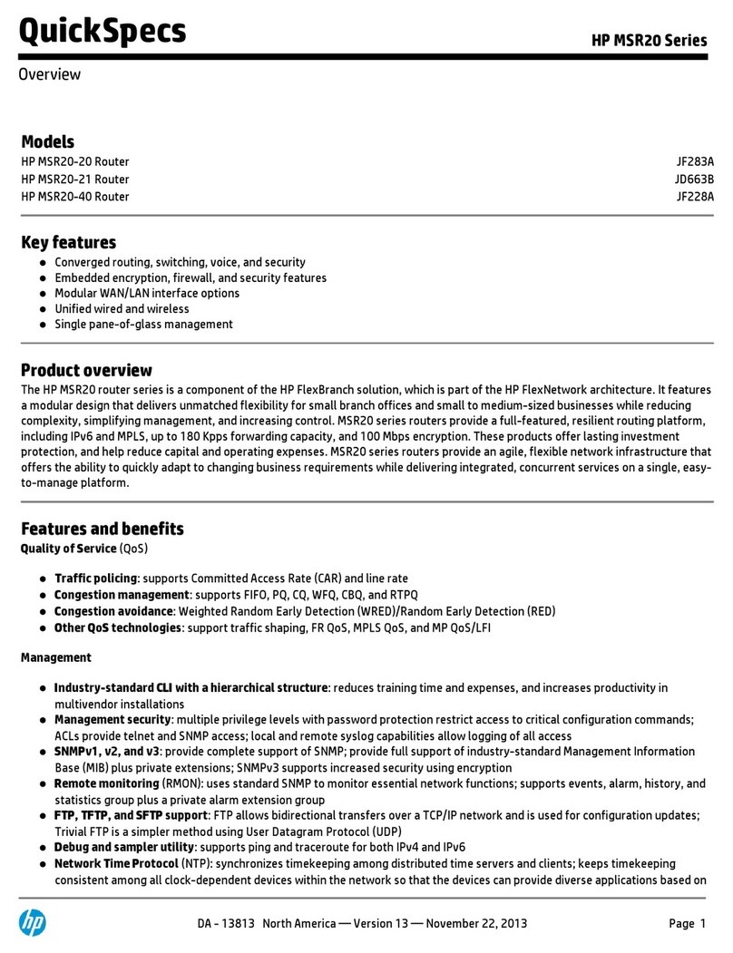
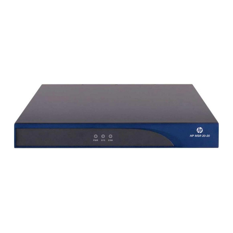
HP MSR SERIES User manual

HP MSR Router Series
Interface
Configuration Guide(V7)
Part number: 5998-6361a
Software version: CMW710-R0106
Document version: 6PW101-20140807

Legal and notice information
© Copyright 2014 Hewlett-Packard Development Company, L.P.
No part of this documentation may be reproduced or transmitted in any form or by any means without
prior written consent of Hewlett-Packard Development Company, L.P.
The information contained herein is subject to change without notice.
HEWLETT-PACKARD COMPANY MAKES NO WARRANTY OF ANY KIND WITH REGARD TO THIS
MATERIAL, INCLUDING, BUT NOT LIMITED TO, THE IMPLIED WARRANTIES OF MERCHANTABILITY
AND FITNESS FOR A PARTICULAR PURPOSE. Hewlett-Packard shall not be liable for errors contained
herein or for incidental or consequential damages in connection with the furnishing, performance, or use
of this material.
The only warranties for HP products and services are set forth in the express warranty statements
accompanying such products and services. Nothing herein should be construed as constituting an
additional warranty. HP shall not be liable for technical or editorial errors or omissions contained herein.
i

Contents
Legal and notice information·········································································································································i
Bulk configuring interfaces ·········································································································································· 1
Configuration restrictions and guidelines·······················································································································1
Configuration procedure··················································································································································1
Displaying and maintaining bulk interface configuration·····························································································2
Configuring Ethernet interfaces··································································································································· 3
Configuring common Ethernet interface settings ···········································································································3
Configuring a combo interface·······························································································································3
Configuring basic settings of an Ethernet interface or subinterface ···································································4
Configuring the link mode of an Ethernet interface······························································································5
Configuring jumbo frame support ··························································································································6
Configuring dampening on an Ethernet interface ································································································7
Performing a loopback test on an Ethernet interface····························································································8
Configuring generic flow control on an Ethernet interface··················································································9
Setting the statistics polling interval····················································································································· 10
Configuring a Layer 2 Ethernet interface ···················································································································· 10
Configuring storm suppression ···························································································································· 10
Setting the MDIX mode of an Ethernet interface ································································································ 11
Configuring a Layer 3 Ethernet interface or subinterface·························································································· 11
Setting the MTU for an Ethernet interface or subinterface ················································································ 11
Configuring the MAC address of an Ethernet interface or subinterface ························································· 12
Displaying and maintaining an Ethernet interface or subinterface··········································································· 12
Configuring WAN interfaces····································································································································14
Configuring a serial interface······································································································································· 14
Asynchronous serial interface ······························································································································ 14
Synchronous serial interface ································································································································ 14
Configuring an asynchronous serial interface ··································································································· 15
Configuring a synchronous serial interface········································································································ 16
Displaying and maintaining serial interfaces····································································································· 17
Configuring an AM interface········································································································································ 17
Configuration procedure ······································································································································ 18
Displaying and maintaining AM interfaces········································································································ 19
Configuring an ISDN BRI interface ······························································································································ 19
Configuration prerequisites ·································································································································· 20
Configuration procedure ······································································································································ 20
Displaying and maintaining ISDN BRI interfaces ······························································································ 21
Configuring a CE1/PRI interface ································································································································· 21
Configuring a CE1/PRI interface in E1 mode···································································································· 22
Configuring a CE1/PRI interface in CE1 mode································································································· 22
Configuring a CE1/PRI interface in PRI mode ··································································································· 23
Configuring other CE1/PRI interface parameters······························································································ 23
Displaying and maintaining CE1/PRI interfaces ······························································································· 24
Configuring a CT1/PRI interface·································································································································· 25
Configuring a CT1/PRI interface in CT1 mode ································································································· 25
Configuring a CT1/PRI interface in PRI mode ··································································································· 25
Configuring other CT1/PRI interface parameters ······························································································ 26
Starting a BERT test on a CT1/PRI interface······································································································· 27
i

Displaying and maintaining CT1/PRI interfaces································································································ 28
Configuring an E1-F interface······································································································································· 28
Configuring an E1-F interface in framed mode·································································································· 28
Configuring an E1-F interface in unframed mode ····························································································· 29
Configuring other E1-F interface parameters ····································································································· 29
Displaying and maintaining E1-F interfaces······································································································· 30
Configuring a T1-F interface ········································································································································· 30
Configuration procedure ······································································································································ 31
Starting a BERT test on a T1-F interface ·············································································································· 32
Displaying and maintaining T1-F interfaces ······································································································· 33
Configuring a CE3 interface········································································································································· 33
Configuring a CE3 interface in E3 mode ··········································································································· 34
Configuring a CE3 interface in CE3 mode ········································································································ 34
Displaying and maintaining CE3 interfaces······································································································· 36
Configuring a CT3 interface········································································································································· 36
Configuring a CT3 interface in T3 mode············································································································ 37
Configuring a CT3 interface in CT3 mode········································································································· 38
Displaying and maintaining CT3 interfaces ······································································································· 40
Configuring POS interfaces·······································································································································42
Overview········································································································································································· 42
SONET and SDH··················································································································································· 42
POS········································································································································································· 42
Feature and hardware compatibility···························································································································· 42
Configuring a standard POS interface ························································································································ 43
Configuring a POS channel interface·························································································································· 44
Displaying and maintaining POS interfaces ··············································································································· 45
POS interface configuration example·························································································································· 45
Network requirements··········································································································································· 45
Configuration procedure ······································································································································ 45
Verifying the configuration··································································································································· 46
Troubleshooting POS interfaces···································································································································· 46
Symptom 1 ····························································································································································· 46
Solution··································································································································································· 46
Symptom 2 ····························································································································································· 46
Solution··································································································································································· 46
Symptom 3 ····························································································································································· 47
Solution··································································································································································· 47
Configuring CPOS interfaces····································································································································48
Overview········································································································································································· 48
Overhead bytes ····················································································································································· 48
CPOS interface application scenarios ················································································································ 49
Feature and hardware compatibility···························································································································· 49
CPOS interface configuration task list ························································································································· 50
Configuring the operating mode of an interface card······························································································· 50
Configuring basic functions of a CPOS interface······································································································· 50
Configuring an E1 channel··········································································································································· 51
Configuring a T1 channel ············································································································································· 52
Displaying and maintaining CPOS interfaces ············································································································ 53
CPOS-E1 interface configuration example·················································································································· 53
Network requirements··········································································································································· 53
Configuration procedure ······································································································································ 54
Verifying the configuration··································································································································· 55
Troubleshooting CPOS interfaces································································································································· 55
ii
iii
Interface physical status is up, link protocol status is down, and loopback is detected································ 55
Configuring ATM interfaces ······································································································································57
Overview········································································································································································· 57
ATM and DSL························································································································································· 57
ATM interface types ·············································································································································· 57
ATM interface features·········································································································································· 57
Configuring an ATM OC-3c/STM-1 interface ············································································································ 58
Configuring an ADSL interface····································································································································· 59
Overview································································································································································ 59
Configuration procedure ······································································································································ 60
Configuring a G.SHDSL interface ································································································································ 61
Overview································································································································································ 61
Configuration procedure ······································································································································ 61
Configuring an ATM subinterface································································································································ 63
Configuring an EFM interface ······································································································································ 63
Configuring an EFM subinterface································································································································· 65
Displaying and maintaining ATM interfaces··············································································································· 65
Troubleshooting ATM interfaces··································································································································· 66
Interface state error ··············································································································································· 66
Frequent packet dropping, CRC check errors, and interface state errors······················································· 66
Troubleshooting DSL interfaces ···························································································································· 66
Configuring loopback, null, and inloopback interfaces··························································································68
Configuring a loopback interface ································································································································ 68
Configuring a null interface ·········································································································································· 69
Configuring an inloopback interface··························································································································· 69
Displaying and maintaining loopback, null, and inloopback interfaces ································································· 69
Support and other resources ·····································································································································70
Contacting HP ································································································································································ 70
Subscription service ·············································································································································· 70
Related information························································································································································ 70
Documents······························································································································································ 70
Websites································································································································································· 70
Conventions ···································································································································································· 71
Index ···········································································································································································73

Bulk configuring interfaces
You can enter interface range view to bulk configure multiple interfaces with the same feature instead of
configuring them one by one. For example, you can execute the shutdown command in interface range
view to shut down a range of interfaces.
Configuration restrictions and guidelines
When you bulk configure interfaces in interface range view, follow these restrictions and guidelines:
•In interface range view, only the commands supported by the first interface are available. The first
interface is specified with the interface range command.
•You cannot enter the view of some interfaces by using the interface interface-type
{ interface-number | interface-number.subnumber } command, for example, BRI 2/1/1:1. Do not
configure any of these interfaces as the first interface in the interface range.
•Do not assign both an aggregate interface and any of its member interfaces to an interface range.
Some commands, after being executed on both an aggregate interface and its member interfaces,
can break up the aggregation.
•No limit is set on the maximum number of interfaces in an interface range. The more interfaces in
an interface range, the longer the command execution time.
•The maximum number of interface range names is only limited by the system resources. To
guarantee bulk interface configuration performance, HP recommends that you configure fewer than
1000 interface range names.
•If a command fails to take effect on the first interface in an interface range, the command does not
take effect on any other member interfaces. Failure to apply a command on a non-first member
interface does not affect the application of the command on the other member interfaces.
Configuration procedure
To bulk configure interfaces:
Step Command Remarks
1. Enter system view. system-view N/A
2. Enter interface range
view.
•interface range { interface-type
interface-number [ to
interface-type
interface-number ] } &<1-5>
•interface range name name
[ interface { interface-type
interface-number [ to
interface-type
interface-number ] } &<1-5> ]
By using the interface range name
command, you assign a name to an
interface range and can specify this
name rather than the interface range to
enter the interface range view.
1

2
Step Command Remarks
3. (Optional.) Display
commands available for
the first interface in the
interface range.
Enter a question mark (?) at the
interface range prompt. N/A
4. Use available
commands to configure
the interfaces.
Available commands vary by
interface. N/A
5. (Optional.) Verify the
configuration. display this N/A
Displaying and maintaining bulk interface
configuration
Execute the display command in any view.
Task Command
Display information about the interface ranges
created by using the interface range name command.
display interface range [name name ]

Configuring Ethernet interfaces
In this chapter, "MSR1000" refers to MSR1002-4. "MSR2000" refers to MSR2003, MSR2004-24,
MSR2004-48. "MSR3000" collectively refers to MSR3012, MSR3024, MSR3044, MSR3064.
"MSR4000" collectively refers to MSR4060 and MSR4080.
Your device supports the following types of Ethernet interfaces:
•Layer 2 Ethernet interfaces—Physical Ethernet interfaces operating at the data link layer (Layer 2)
to switch packets.
•Layer 3 Ethernet interfaces—Physical Ethernet interfaces operating at the network layer (Layer 3) to
route packets. You can assign an IP address to a Layer 3 Ethernet interface.
•Layer-configurable Ethernet interfaces—Physical Ethernet interfaces that can be configured to
operate in bridge mode as Layer 2 Ethernet interfaces or in route-mode as Layer 3 Ethernet
interfaces.
•Layer 3 Ethernet subinterfaces—Logical interfaces operating at the network layer. You can assign
an IP address to a Layer 3 Ethernet subinterface. By creating subinterfaces on a Layer 3 Ethernet
interface, you enable the interface to carry packets for multiple VLANs. For how a Layer 3 Ethernet
subinterface sends and receives VLAN-tagged packets, see Layer 2—LAN Switching Configuration
Guide.
Configuring common Ethernet interface settings
This section describes the settings common to Layer 2 and Layer 3 Ethernet interfaces or subinterfaces.
For more information about the settings specific to Layer 2 and Layer 3 Ethernet interfaces or
subinterfaces, see "Configuring a Layer 2 Ethernet interface" and "Configuring a Layer 3 Ethernet
interface or subinterface."
Configuring a combo interface
A combo interface is a logical interface that physically comprises one fiber port and one copper port.
The two ports share one forwarding channel and one interface view, so they cannot work simultaneously.
When you activate one port, the other port is automatically disabled. In the interface view, you can
activate the fiber or copper combo port, and configure other port attributes such as the interface rate and
duplex mode.
Configuration prerequisites
Before you configure combo interfaces, complete the following tasks:
•Determine the combo interfaces on your device and identify the two physical interfaces that
compose each combo interface according to the marks on the device panel.
•Use the display interface command to determine which port (fiber or copper) of the combo
interface is active. If the current port is the copper port, the output includes "Media type is twisted
pair, Port hardware type is 1000_BASE_T." If the current port is the fiber port, the output does not
include this information. You can also use the display this command in the view of the combo
interface to view the combo interface configuration. If the combo enable fiber command exists, the
fiber port is active. If the command does not exist, the copper port is active.
3

Changing the active port of a combo interface
Step Command Remarks
1. Enter system view. system-view N/A
2. Enter Ethernet interface view. interface interface-type
interface-number N/A
3. Activate the copper combo
port or fiber combo port. combo enable {copper |fiber }By default, the copper combo port
is active.
Configuring basic settings of an Ethernet interface or
subinterface
You can set an Ethernet interface to operate in one of the following duplex modes:
•Full-duplex mode (full)—Interfaces can send and receive packets simultaneously.
•Half-duplex mode (half)—Interfaces cannot send and receive packets simultaneously.
•Autonegotiation mode (auto)—Interfaces negotiate a duplex mode with their peers.
You can set the speed of an Ethernet interface or enable it to automatically negotiate a speed with its
peer.
Configuring an Ethernet interface
Step Command Remarks
1. Enter system view. system-view N/A
2. Enter Ethernet interface
view.
interface interface-type
interface-number N/A
3. Set the interface
description. description text
The default setting is in the format of
interface-name Interface. For example,
GigabitEthernet2/0/1 Interface.
4. Set the duplex mode of
the Ethernet interface. duplex { auto | full | half }
The default setting is full for 10-GE
interfaces and auto for other Ethernet
interfaces.
Fiber ports do not support the half
keyword.
5. Set the port speed. speed { 10 | 100 |1000 |
10000 | auto }
By default, the auto keyword is used.
Support for the keywords of the command
depends on the interface type. For more
information, see Interface Command
References.
6. Configure the expected
bandwidth of the
interface.
bandwidth bandwidth-value
By default, the expected bandwidth (in
kbps) is the interface baud rate divided by
1000.
7. Restore the default
settings for the Ethernet
interface.
default N/A
4

Step Command Remarks
8. Bring up the Ethernet
interface. undo shutdown By default, the Ethernet interface is down.
Configuring an Ethernet subinterface
Ste
p
Command
Remarks
1. Enter system view. system-view N/A
2. Create an Ethernet
subinterface.
interface interface-type
interface-number.subnumber N/A
3. Set the interface description. description text
The default setting is
interface-name Interface. For
example, GigabitEthernet2/0/1.1
Interface.
4. Restore the default settings for
the Ethernet subinterface. default N/A
5. Configure the expected
bandwidth of the interface. bandwidth bandwidth-value
By default, the expected
bandwidth (in kbps) is the interface
baud rate divided by 1000.
6. Bring up the Ethernet
subinterface. undo shutdown By default, the Ethernet
subinterface is down.
For the local and remote Ethernet subinterfaces to transmit traffic correctly, configure them with the same
subinterface number and VLAN ID.
Configuring the link mode of an Ethernet interface
CAUTION:
A
fter you chan
g
e the link mode of an Ethernet interface, all commands (except the shutdown command)
on the Ethernet interface are restored to their defaults in the new link mode.
Interfaces operate differently depending on the hardware structure of interface cards. For a device:
•Some interfaces can operate only as Layer 2 Ethernet interfaces (in bridge mode).
•Some interfaces can operate only as Layer 3 Ethernet interfaces (in route mode).
•Some interfaces can operate either as Layer 2 or Layer 3 Ethernet interfaces.
You can set the link mode to bridge or route.
To change the link mode of an Ethernet interface:
Step Command Remarks
1. Enter system view. system-view N/A
2. Enter Ethernet interface view. interface interface-type
interface-number N/A
5

Step Command Remarks
3. Change the link mode of the
Ethernet interface. port link-mode { bridge | route }
By default, the following
interfaces operate as Layer 2
Ethernet interfaces:
•Ethernet interfaces on a
SIC-4FSW, SIC-4GSW,
DSIC-9FSW, HMIM-8GSW,
or HMIM-24GSW interface
card.
•Ethernet interfaces
GigabitEthernet 0/3 to
GigabitEthernet 0/27 on an
MSR2004-24 router.
•Ethernet interfaces
GigabitEthernet 0/3 to
GigabitEthernet 0/50 on an
MSR2004-48 router.
Configuring jumbo frame support
An Ethernet interface might receive some frames larger than the standard Ethernet frame size (called
"jumbo frames") during high-throughput data exchanges, such as file transfers.
The Ethernet interface processes jumbo frames in the following ways:
•When the Ethernet interface is configured to deny jumbo frames, the Ethernet interface discards
jumbo frames without further processing.
•When the Ethernet interface is configured with jumbo frame support, the Ethernet interface:
{Processes jumbo frames within the specified length.
{Discards jumbo frames beyond the specified length without further processing.
To configure jumbo frame support in interface view:
Step Command Remarks
1. Enter system view. system-view N/A
2. Enter Ethernet interface
view.
interface interface-type
interface-number N/A
3. Configure jumbo frame
support. jumboframe enable [ value ]
By default, the device allows jumbo
frames within the specified length to
pass through all Layer 2 Ethernet
interfaces. The length of jumbo frames
that are allowed to pass depends on
the device model. For more
information, see Interface Command
References.
If you set the value argument multiple
times, the most recent configuration
takes effect.
6

Configuring dampening on an Ethernet interface
The interface dampening feature uses an exponential decay mechanism to suppress the effects of
excessive interface flapping events on routing protocols and routing tables in the network. Suppressing
interface state change events protects the system processing resources.
If an interface is not dampened, its state changes are reported. For each state change, the system also
generates an SNMP notification and log message.
After a flapping interface is dampened, it does not report its state changes to the CPU. For state change
events, the interface only generates SNMP notifications and log messages.
Parameters
•Penalty—The interface has a initiate penalty of 0. When the interface flaps, it is assigned a penalty
of 1000 for each down even, and does not increase for up events.
•Ceiling—The penalty stops increasing after it reaches the ceiling.
•Suppress-limit—The accumulated penalty that triggers the device to dampen the interface. In
dampened state, the interface does not report its state changes to the CPU. For state change events,
the interface only generates SNMP notifications and log messages
•Reuse-limit—When the accumulated penalty decreases to this reuse threshold, the interface is not
dampened. Interface state changes are reported to the higher layers. For each state change, the
system also generates an SNMP notification and log message.
•Decay—The amount of time (in seconds) after which a penalty is decreased.
•Max-suppress-time—The maximum amount of time the interface can be dampened. If the penalty
is still higher than the reuse threshold when this timer expires, the penalty stops increasing for down
events.
The maximum penalty is equal to 2(Max-suppress-time/Decay) × reuse-limit. It is not user configurable.
Figure 1 shows the change rule of the penalty value. t0and t2indicate the start time and end time of the
suppression, respectively. The period from t0to t2indicates the suppression period, t0to t1indicates the
max-suppress-time, and t1to t2indicates the complete decay period.
7

Figure 1 Change rule of the penalty value
Not suppressed Not suppressedSuppressed
Penalty
Time
Reuse limit
Suppress limit
Ceiling
t0t1t2
Configuration restrictions and guidelines
The dampening command does not take effect on the administratively down events. When you execute
the shutdown command, the penalty restores to 0, and the interface reports the down event to the higher
layer protocols.
Configuration procedure
To configure dampening on an Ethernet interface:
Step Command Remarks
1. Enter system view. system-view N/A
2. Enter Ethernet interface
view.
interface interface-type
interface-number N/A
3. Enable dampening on
the interface.
dampening [half-life reuse
suppress max-suppress-time ]
By default, interface dampening is
disabled on Ethernet interfaces.
Performing a loopback test on an Ethernet interface
If an Ethernet interface does not work correctly, you can perform a loopback test on it to identify the
problem. An Ethernet interface in a loopback test does not forward data traffic.
Only internal loopback tests are supported. In an internal loopback test, all on-chip functions related to
the Ethernet interface are tested.
8

Configuration restrictions and guidelines
•On an administratively shut down Ethernet interface (displayed as in ADM or Administratively
DOWN state), you cannot perform an internal loopback test.
•The speed, duplex, mdix-mode, and shutdown commands are not available during a loopback
test.
•During a loopback test, the Ethernet interface operates in full duplex mode. When a loopback test
is complete, the port returns to its duplex setting.
Configuration procedure
Step Command Remarks
1. Enter system view. system-view N/A
2. Enter Ethernet interface view. interface interface-type
interface-number N/A
3. Perform a loopback test. loopback internal By default, no loopback test is
performed.
Configuring generic flow control on an Ethernet interface
To avoid packet drops on a link, you can enable generic flow control at both ends of the link. When
traffic congestion occurs at the receiving end, the receiving end sends a flow control (Pause) frame to ask
the sending end to suspend sending packets.
•With TxRx mode generic flow control enabled, an interface can both send and receive flow control
frames. When congestion occurs, the interface sends a flow control frame to its peer. When the
interface receives a flow control frame from the peer, it suspends sending packets.
•With Rx flow mode generic control enabled, an interface can receive flow control frames, but it
cannot send flow control frames. When the interface receives a flow control frame from its peer, it
suspends sending packets to the peer. When congestion occurs, the interface cannot send flow
control frames to the peer.
To handle unidirectional traffic congestion on a link, configure the flow-control receive enable command
at one end and the flow-control command at the other end. To enable both ends of a link to handle traffic
congestion, configure the flow-control command at both ends.
To enable generic flow control on an Ethernet interface:
Step Command Remarks
1. Enter system view. system-view N/A
2. Enter Ethernet interface
view.
interface interface-type
interface-number N/A
3. Enable generic flow control.
•Enable TxRx mode generic
flow control:
flow-control
•Enable Rx mode generic flow
control:
flow-control receive enable
By default, generic flow control is
disabled on an Ethernet interface.
9

Setting the statistics polling interval
Step Command Remarks
1. Enter system view. system-view N/A
2. Set the statistics polling
interval. flow-interval interval
By default, the statistics polling interval
is 300 seconds.
Settings in system view take effect on
all Ethernet interfaces.
To display the interface statistics collected in the last polling interval, use the display interface command.
To clear interface statistics, use the reset counters interface command.
Configuring a Layer 2 Ethernet interface
Configuring storm suppression
You can use the storm suppression function to limit the size of a particular type of traffic (broadcast,
multicast, or unknown unicast traffic) on an interface. When the broadcast, multicast, or unknown unicast
traffic on the interface exceeds this threshold, the system discards packets until the traffic drops below this
threshold.
Configuration guidelines
When you configure the suppression threshold in pps, the device might convert the configured value into
a multiple of a certain step supported by the chip. As a result, the actual suppression threshold might be
different from the configured one. For the suppression threshold that takes effect, see the prompt on the
device.
Configuration procedure
To set storm suppression thresholds on one or multiple Ethernet interfaces:
Step Command Remarks
1. Enter system view. system-view N/A
2. Enter Ethernet interface or
subinterface view.
interface interface-type
{ interface-number |
interface-number.subnumber }
N/A
3. Enable broadcast suppression
and set the broadcast
suppression threshold.
broadcast-suppression { ratio |
pps max-pps }
By default, broadcast traffic is
allowed to pass through an
interface.
4. Enable multicast suppression
and set the multicast
suppression threshold.
multicast-suppression { ratio |pps
max-pps }
By default, multicast traffic is
allowed to pass through an
interface.
5. Enable unknown unicast
suppression and set the
unknown unicast suppression
threshold.
unicast-suppression { ratio |pps
max-pps }
By default, unknown unicast traffic
is allowed to pass through an
interface.
10

Setting the MDIX mode of an Ethernet interface
NOTE:
Fiber ports do not support the MDIX mode setting.
A physical Ethernet interface comprises eight pins, each of which plays a dedicated role. For example,
pins 1 and 2 transmit signals, and pins 3 and 6 receive signals. You can use both crossover and
straight-through Ethernet cables to connect copper Ethernet interfaces. To accommodate these types of
cables, a copper Ethernet interface can operate in one of the following Medium Dependent
Interface-Crossover (MDIX) modes:
•MDIX mode—Pins 1 and 2 are receive pins and pins 3 and 6 are transmit pins.
•MDI mode—Pins 1 and 2 are transmit pins and pins 3 and 6 are receive pins.
•AutoMDIX mode—The interface negotiates pin roles with its peer.
To enable the interface to communicate with its peer, set the MDIX mode of the interface mode by using
the following guidelines:
•Generally, set the MDIX mode of the interface to AutoMDIX. Set the MDIX mode of the interface to
MDI or MDIX only when the device cannot determine the cable type.
•When a straight-through cable is used, set the interface to operate in the MDIX mode different than
its peer.
•When a crossover cable is used, set the interface to operate in the same MDIX mode as its peer, or
set either end to operate in AutoMDIX mode.
To set the MDIX mode of an Ethernet interface:
Ste
p
Command
Remarks
1. Enter system view. system-view N/A
2. Enter Ethernet interface view. interface interface-type
interface-number N/A
3. Set the MDIX mode of the
Ethernet interface.
mdix-mode {automdix |mdi |
mdix }
By default, a copper Ethernet
interface operates in auto mode to
negotiate pin roles with its peer.
Configuring a Layer 3 Ethernet interface or
subinterface
Setting the MTU for an Ethernet interface or subinterface
The value of maximum transmission unit (MTU) affects the fragmentation and reassembly of IP packets.
Generally, you do not need to modify the MTU of an interface.
To set the MTU for an Ethernet interface or subinterface:
11

Step Command Remarks
1. Enter system view. system-view N/A
2. Enter Ethernet interface
or subinterface view.
interface interface-type { interface-number |
interface-number.subnumber } N/A
3. Set the MTU. mtu size
The default setting varies by
interface types. For more
information, see Interface
Command References.
Configuring the MAC address of an Ethernet interface or
subinterface
In a network, when the Layer 3 Ethernet interfaces or subinterfaces of different devices have the same
MAC address, the devices might fail to communicate correctly. To eliminate the MAC address conflicts,
use the mac-address command to modify the MAC addresses of Layer 3 Ethernet interfaces or
subinterfaces.
Additionally, when a Layer 3 Ethernet subinterface is created, it uses the MAC address of its main
interface by default. As a result, all Layer 3 Ethernet subinterfaces of a Layer 3 Ethernet interface share
the same MAC address. To configure a different MAC address for a specific Layer 3 Ethernet
subinterface, use the mac-address command.
To configure the MAC address of an Ethernet interface or subinterface:
Ste
p
Command
Remarks
1. Enter system view. system-view N/A
2. Enter Ethernet interface view.
interface interface-type
{ interface-number |
interface-number.subnumber }
N/A
3. Configure the MAC address
of the Ethernet interface or
subinterface.
mac-address mac-address
The default MAC address of a Layer 3
Ethernet interface varies by devices.
The default MAC address of a Layer 3
Ethernet subinterface is the same as the
MAC address of its host interface.
HP recommends not configuring a
MAC address in the VRRP-reserved
MAC address range for a Layer 3
Ethernet subinterface.
Displaying and maintaining an Ethernet interface or
subinterface
Execute display commands in any view and reset commands in user view.
12

13
Task Command
Display interface traffic statistics. display counters {inbound |outbound }interface [ interface-type
[ interface-number | interface-number.subnumber ] ]
Display traffic rate statistics of interfaces in
up state over the last sampling interval.
display counters rate {inbound |outbound }interface
[ interface-type [ interface-number |
interface-number.subnumber ] ]
Display the operational and status
information of the specified interface or all
interfaces.
display interface [ interface-type [ interface-number |
interface-number.subnumber ] ] [ brief [ description | down ] ]
Display information about dropped
packets on the specified interface or all
interfaces.
display packet-drop { interface [ interface-type
[interface-number ] ] | summary }
Display the Ethernet statistics
(MSR1000/MSR2000/MSR3000). display ethernet statistics
Display the Ethernet statistics (MSR4000).
display ethernet statistics slot slot-number
Clear the interface or subinterface
statistics.
reset counters interface [ interface-type [ interface-number |
interface-number.subnumber ] ]
Clear the statistics of dropped packets on
the specified interfaces. reset packet-drop interface [ interface-type [ interface-number ] ]
Clear the Ethernet statistics
(MSR1000/MSR2000/MSR3000). reset ethernet statistics
Clear the Ethernet statistics (MSR4000). reset ethernet statistics slot slot-number

Configuring WAN interfaces
This chapter describes how to configure interfaces for connecting to WAN networks, including ATM and
ISDN. Available WAN interfaces include the asynchronous serial interface, synchronous serial interface,
ATM interface, ISDN BRI interface, and CE1/PRI interface.
For more information about ATM interfaces, see "Configuring ATM interfaces."
Configuring a serial interface
Asynchronous serial interface
The following types of asynchronous serial interfaces are available:
•Synchronous/asynchronous serial interface operating in asynchronous mode. The interface type
name is Serial.
•Dedicated asynchronous serial interface. The interface type name is Async.
You can connect a modem or ISDN terminal adapter to an asynchronous serial interface for dial-up
connection.
An asynchronous serial interface can operate in protocol or flow mode.
•Protocol mode—Data is transmitted in packets. The link layer protocol can only be PPP. The network
layer protocol is typically IP.
•Flow mode—Data is transmitted as character flows. This mode is typically used in human-machine
interaction scenarios such as dial-up access. After the physical connection is established, you can
send commands to set up a link with the asynchronous serial interface, and then configure the
device.
Synchronous serial interface
Synchronous serial interfaces refer to synchronous/asynchronous serial interfaces operating in
synchronous mode. They provide serial communication channels for synchronous data transmission. The
interface type name is Serial.
A synchronous serial interface operates in DCE or DTE mode. Two directly connected synchronous serial
interfaces must operate in different modes.
•In DCE mode, the interface provides timing for synchronization and sets the baud rate.
•In DTE mode, the interface accepts the timing signal and baud rate from the DCE.
The synchronous serial interfaces on the device are typically operating as DTE.
A synchronous interface can be connected to various types of cables, including V.24, V.35, X.21, RS449,
and RS530. Typically, the device can automatically recognize the cable type and select electrical
properties.
The synchronous serial interface supports multiple data link layer protocols, including PPP and HDLC. The
interface supports IP at the network layer.
14

Configuring an asynchronous serial interface
This section only describes the interface properties configuration. Depending on the network
requirements, you might also need to configure PPP, DDR, IP address, firewall, and interface backup.
To configure an asynchronous serial interface:
Step Command Remarks
1. Enter system view. system-view N/A
2. Enter asynchronous serial
interface view.
interface async interface-number
or
interface serial interface-number
N/A
3. (Optional.) Set the interface
description. description text
By default, the description of an
asynchronous serial interface is
interface name Interface, for
example, Serial2/1/0 Interface.
4. Configure a synchronous or
asynchronous serial interface
to operate as an
asynchronous serial interface.
physical-mode async
By default, a synchronous or
asynchronous serial interface
operates as a synchronous serial
interface.
Skip this step if the interface is an
asynchronous interface.
5. Set the link layer protocol. link-protocol ppp The default is PPP.
6. Set the operating mode. async mode { flow | protocol } The default is the protocol mode.
7. (Optional.) Enable level
detection. detect dsr-dtr By default, level detection is
enabled.
8. (Optional.) Enable local
loopback. loopback By default, local loopback is
disabled.
9. Set the MTU. mtu size The default is 1500 bytes.
10. Set the keepalive transmission
interval. timer-hold seconds The default is 10 seconds.
11. (Optional.) Eliminate the
pulses with a width less than
3.472 μs.
eliminate-pulse By default, the pulses with a width
less than 1.472 μs are eliminated.
12. Set the MRU for an interface
operating in flow mode. phy-mru mrusize The default MRU is 1700 bytes.
13. (Optional.) Set the intended
bandwidth for the
asynchronous serial interface.
bandwidth bandwidth-value
By default, the expected
bandwidth (in kbps) is the interface
baud rate divided by 1000.
14. (Optional.) Restore the default
settings for the asynchronous
serial interface.
default N/A
15. Bring up the asynchronous
serial interface. undo shutdown By default, an asynchronous serial
interface is up.
15
Other manuals for MSR SERIES
14
Table of contents
Other HP Network Router manuals

HP
HP MSR SERIES User manual

HP
HP FlexFabric 5930 Series User manual

HP
HP 5920 User manual

HP
HP Pavilion a6600 User manual

HP
HP FlexNetwork HSR6802 User manual

HP
HP MSR1002-4 User manual

HP
HP 16Gb SAN User manual

HP
HP FlexNetwork MSR3044 Assembly instructions

HP
HP MSR2000 Series User manual

HP
HP MSR1003-8S User manual

HP
HP A8800 Series Installation manual

HP
HP MSR954 Series User manual

HP
HP Deskjet 812c Instruction Manual

HP
HP 10500 series User manual

HP
HP 6400/8400 User manual

HP
HP FlexNetwork MSR 954 User manual

HP
HP A5500 EI Switch Series Installation manual

HP
HP HP ProCurve Series 6600 Installation manual

HP
HP ProCurve J9065A User manual

HP
HP 7000dl Series User manual