Important safety information
NOTE: The extension bars that ship with this kit are only
for use with Compaq/HP models EO4500, EO4501,
EO4502, EO4503, EO4504, EO4505, EO4506,
HSTNR-P011, and HSTNR-P012 Power Distribution
Control Units and HP Uninterruptible Power Supplies
(UPS).
WARNING: To reduce the risk of personal injury from
electric shock, do not remove the cover. There are no field-
serviceable or user-serviceable components inside.
WARNING: A risk of personal injury from electric shock
and hazardous energy levels exists. The installation of
options and routine maintenance and service of this
product must be performed by individuals who are
knowledgeable about the procedures, precautions, and
hazards associated with AC power products.
Follow these safety precautions when connecting multiple hardware
components to power sources.
WARNING: To reduce the risk of personal injury or
damage to the equipment:
•Plug the input power cord into a grounded (earthed)
electrical outlet that is located near the equipment and
is easily accessible.
•Be sure that the load products connected to the mPDU
are adjusted for, or otherwise capable of operation
from the same line voltage supplying the mPDU. Failure
to verify the voltage can lead to severe equipment
damage.
•Do not overload the mPDU. The total input current
rating of all equipment connected to each output
cannot exceed the total output rating marked on the
mPDU.
WARNING: To reduce the risk of personal injury from
high-leakage current, verify earth connection before
connecting the power supply.
The summation of input power for multiple pieces of
information technology equipment through the use of
power products can result in high-leakage currents.
If the total system leakage current for a system of
components exceeds 3.5 mA:
•The use of a detachable input power cord is
prohibited.
•The input power cord must be securely attached, and it
should be connected to the AC mains by hardwiring or
through the use of a non-residential, industrial-style
plug that maintains positive earth connection.
•If the total system leakage current through the ground
conductor exceeds 5% of the input current per line
under normal operating conditions, the system loads
should be divided among multiple power connections.
Regulatory compliance information
All regulatory certifications for these products were obtained under
the following agency series numbers:
Control unit Series number
228481-001 EO4500
228481-002 EO4501
228481-003 EO4502
228481-004 EO4503
228481-006 EO4504
228481-007 EO4505
228481-008 E04506
435530-001 HSTNR-P011
435530-003 HSTNR-P012
458745-001 HSTNR-P016N
481337-001 HSTNR-P017
484168-001 HSTNR-P016-A
Extension bar Series number
411273-001 HSTNR-PS02
411273-002 HSTNR-PS03
228480-003 EO4602
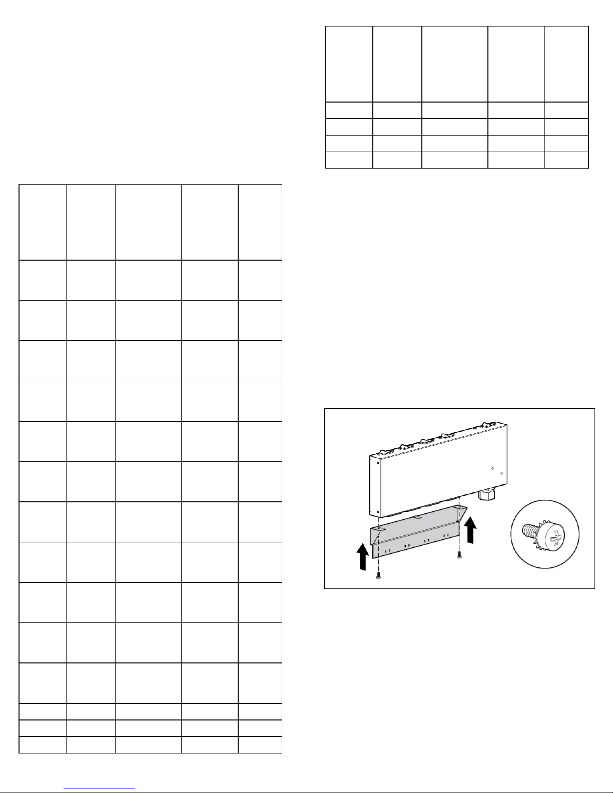
Kit contents
Control unit hardware (if included)
The following hardware pieces are included:
•Control unit with extension bars
o0U mounting brackets (2)
o1U mounting brackets (2)