S&C Remote Supervisory Vista User manual

January 20, 2020
© S&C Electric Company 1999-2020, all rights reserved Instruction Sheet 682-510
Remote Supervisory Vista®Underground Distribution Switchgear
Pad-Mounted, Dry-Vault-Mounted, Wet-Vault-Mounted, and Undercover™ Styles
Introduction
Qualified Persons ........................... 2
Read this Instruction Sheet ................... 2
Retain this Instruction Sheet. . . . . . . . . . . . . . . . . . . 2
Proper Application .......................... 2
Warranty .................................. 2
Safety Information
Understanding Safety-Alert Messages........... 3
Following Safety Instructions .................. 3
Replacement Instructions and Labels ........... 3
Location of Safety Labels ..................... 4
Safety Precautions ......................... 5
Components
Overview of Components ..................... 6
Understanding the Gas Pressure Gauge ......... 9
Gauge Needle Fluctuations from Rapid
Ambient Temperature Changes............... 9
Operation
Manually Opening, Closing, or Grounding a Way ..10
Locking Out Grounded Position ................14
Locking In Closed, Open, or Grounded Position ...15
Electrically Opening, Closing, or
Grounding a Way ..........................16
Motor Operator Decoupling .................. 20
Checking for Voltage Using Optional
VOLTAGE Indicator ....................... 22
Low-Voltage Phasing Using Optional
VOLTAGE Indicator with Phasing ............ 25
Maintenance
Components .............................. 27
Returning Equipment to Service............... 28
Enclosure Finish ........................... 28
Maintenance Recommendations in
Extremely Corrosive Environments ........... 29
Dielectric Testing
Routine Switchgear Testing .................. 30
Cable Testing and Fault Locating ...............31
Fault Interrupter Testing ..................... 31
Resistance Measurement.................... 32
Section Page Section Page
Table of Contents
Operation

2 S&C Instruction Sheet 682-510
Qualified Persons WARNING
The equipment covered by this publication must be installed, operated, and
maintained by qualified persons who are knowledgeable in the installation, operation,
and maintenance of underground electric power distribution equipment along with the
associated hazards. A qualified person is one who is trained and competent in:
• The skills and techniques necessary to distinguish exposed live parts from nonlive
parts of electrical equipment
• The skills and techniques necessary to determine the proper approach distances
corresponding to the voltages to which the qualified person will be exposed
• The proper use of the special precautionary techniques, personal protective
equipment, insulating and shielding materials, and insulated tools for working on
or near exposed energized parts of electrical equipment
These instructions are intended only for such qualified persons. They are not
intended to be a substitute for adequate training and experience in safety
procedures for this type of equipment.
Read this Instruction
Sheet
Read this instruction sheet thoroughly and carefully before installing or operating
your Remote Supervisory Vista Underground Distribution Switchgear. Familiarize
yourself with Safety Information and Safety Precautions on pages 3 through 5. The
latest version of this publication is available in PDF format at sandc.com/en/support/
product-literature/.
Retain this
Instruction Sheet
This instruction sheet is a permanent part of your Remote Supervisory Vista Underground
Distribution Switchgear. Designate a location where you can easily retrieve and refer
to this publication.
Proper Application WARNING
The equipment in this publication must be selected for a specific application. The
application must be within the ratings furnished for the equipment. Ratings for this
gear are listed on a ratings label at the front of the switchgear. See Specification
Bulletin 682-31 for more information.
Warranty The warranty and/or obligations described in S&C’s Price Sheet 150, “Standard Conditions
of Sale–Immediate Purchasers in the United States” (or Price Sheet 153, “Standard
Conditions of Sale–Immediate Purchasers Outside the United States”), plus any special
warranty provisions, as set forth in the applicable product-line specication bulletin,
are exclusive. The remedies provided in the former for breach of these warranties shall
constitute the immediate purchaser’s or end user’s exclusive remedy and a fulllment
of the seller’s entire liability. In no event shall the seller’s liability to the immediate
purchaser or end user exceed the price of the specic product that gives rise to immediate
purchaser’s or end user’s claim. All other warranties, whether express or implied or
arising by operation of law, course of dealing, usage of trade or otherwise, are excluded.
The only warranties are those stated in Price Sheet 150, (or Price Sheet 153) and THERE
ARE NO EXPRESS OR IMPLIED WARRANTIES OF MERCHANTABILITY OR FITNESS
FOR A PARTICULAR PURPOSE. ANY EXPRESS WARRANTY OR OTHER OBLIGATION
PROVIDED IN PRICE SHEET 150 (OR PRICE SHEET 153) IS GRANTED ONLY TO THE
IMMEDIATE PURCHASER AND END USER, AS DEFINED THEREIN. OTHER THAN AN
END USER, NO REMOTE PURCHASER MAY RELY ON ANY AFFIRMATION OF FACT OR
PROMISE THAT RELATES TO THE GOODS DESCRIBED HEREIN, ANY DESCRIPTION
THAT RELATES TO THE GOODS, OR ANY REMEDIAL PROMISE INCLUDED IN PRICE
SHEET 150 (or PRICE SHEET 153).
Introduction

S&C Instruction Sheet 682-510 3
Understanding
Safety-Alert
Messages
Several types of safety-alert messages may appear throughout this instruction sheet and
on labels attached to the Remote Supervisory Vista Switchgear. Familiarize yourself with
these types of messages and the importance of these various signal words:
DANGER
“DANGER” identifies the most serious and immediate hazards that will likely
result in serious personal injury or death if instructions, including recommended
precautions, are not followed.
WARNING
“WARNING” identifies hazards or unsafe practices that can result in serious
personal injury or death if instructions, including recommended precautions, are
not followed.
CAUTION
“CAUTION” identifies hazards or unsafe practices that can result in minor personal
injury if instructions, including recommended precautions, are not followed.
NOTICE
“NOTICE” identifies important procedures or requirements that can result in product
or property damage if instructions are not followed.
Following Safety
Instructions
If you do not understand any portion of this instruction sheet and need assistance, contact
your nearest S&C Sales ofce or S&C Authorized Distributor. Their telephone numbers
are listed on S&C’s website, sandc.com, or call the S&C Global Support and Monitoring
Center at 1-888-762-1100.
NOTICE
Thoroughly and carefully read this instruction sheet
before operating your Remote Supervisory Vista
Underground Distribution Switchgear.
Replacement
Instructions and
Labels
If additional copies of this instruction sheet are needed, contact your nearest S&C Sales
Ofce, S&C Authorized Distributor, S&C Headquarters, or S&C Electric Canada Ltd.
Instruction sheets can also be viewed on S&C’s website: sandc.com.
It is important that any missing, damaged, or faded labels on the equipment be replaced
immediately. Replacement labels are available by contacting your nearest S&C Sales
Office, S&C Authorized Distributor, S&C Headquarters, or S&C Electric Canada Ltd.
Safety Information

4 S&C Instruction Sheet 682-510
Location of Safety Labels
Top of switchgear
Pad-mounted enclosure
Reorder Information for Safety Labels
Location Safety-Alert Message Description Part Number
AWARNING Keep Out—Hazardous Voltage Inside G-6681
BDANGER Hazardous Voltage—Always Consider Circuits and Components Live . . . G-6700
CDANGER Never Drill Into Tank—Hazardous Voltage, Contains Pressurized SF6 Gas G-6682
DDANGER Keep Away—Hazardous Voltage (“Mr. Ouch”) G-6699
EWARNING Check Gas Pressure Before Operating Switchgear G-6686
FWARNING Always Test Voltage Indicator For Proper Operation G-6689
G●WARNING Always Visually Confirm Blade Position
G-6693
G-6694 (Option
“-L2”)
●This label is located on the side of the gear and is not visible in this photo.
Safety Information
A
Top of switchgear
B
C D
E F
G ●

S&C Instruction Sheet 682-510 5
DANGER
Switchgear contains high voltage. Failure to observe the precautions below
will result in serious injury or death.
Some of these precautions may differ from company operating procedures and
rules. Where a discrepancy exists, users should follow their company’s operating
procedures and rules.
1. QUALIFIED PERSONS. Access to switchgear must
be restricted only to qualified persons. See the
“Qualified Persons” section on page 2.
2. SAFETY PROCEDURES. Always follow safe
operating procedures and rules.
3. PERSONAL PROTECTIVE EQUIPMENT. Always
use suitable protective equipment, such as rubber
gloves, rubber mats, hard hats, safety glasses, and
flash clothing, in accordance with safe operating
procedures and rules.
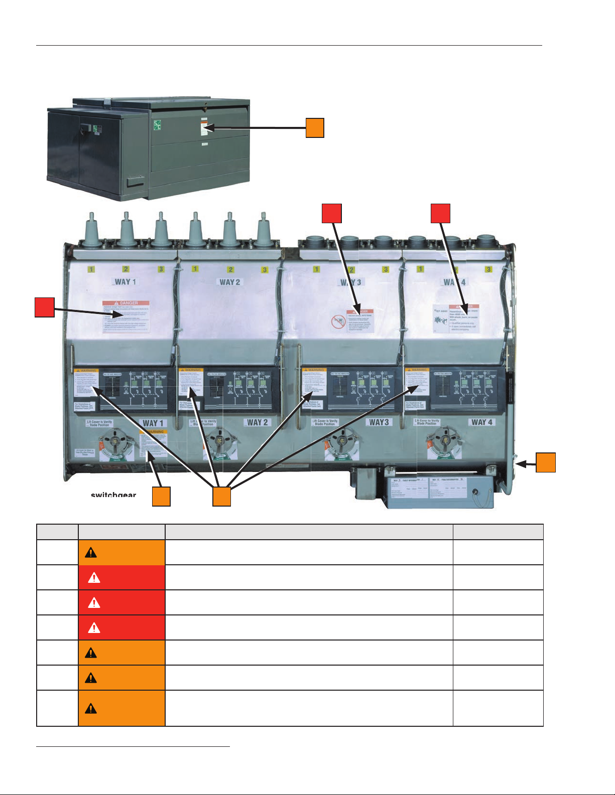
4. SAFETY LABELS. Do not remove or obscure any of
the “CAUTION,” “WARNING,” or “DANGER” labels.
5. CLOSING AND LOCKING ENCLOSURES. The
pad-mounted enclosure and low-voltage
compartment or enclosure must be securely closed
with padlocks in place at all times unless work is
being performed inside.
6. ENERGIZED BUSHINGS. Always assume the
bushings are energized unless proven otherwise by
test, by visual evidence of an open-circuit condition
at the load-interrupter switch or fault interrupter, or by
observing that the load-interrupter switch or fault
interrupter is grounded.
7. BACKFEED. Bushings, cables, load-interrupter
switches, and fault interrupters may be energized by
backfeed.
8. DE-ENERGIZING, TESTING, AND GROUNDING.
Before touching any bushings or components inside
the switchgear that are to be inspected, replaced,
serviced, or repaired, always disconnect load-inter-
rupter switches and fault interrupters from all power
sources (including backfeed), test for voltage, and
properly ground.
9. TESTING. Test the bushings for voltage using the
voltage-indication feature (if furnished) or other
proper high-voltage test equipment before touching
any bushings or components inside the switchgear
that are to be inspected, replaced, serviced, or
repaired.
10. GROUNDING.
• Make sure the switchgear tank and pad-mounted
enclosure are properly grounded to the station or
facility ground. Improper grounding will cause
equipment damage.
• After the switchgear has been completely
disconnected from all sources of power and tested
for voltage, properly ground the load-interrupter
switches and fault interrupters before touching
anybushingsorcomponentsinsidetheswitchgear
that are to be inspected, replaced, serviced, or
repaired.
11. LOAD-INTERRUPTER SWITCH AND FAULT-
INTERRUPTER POSITION.
• Always confirm the Closed/Open/Grounded
position of load-interrupter switches and fault
interrupters by visually observing the position of
the blades.
• Load-interrupter switches and fault interrupters
may be energized by backfeed.
• Load-interrupter switches and fault interrupters
may be energized in any position.
12. MAINTAINING PROPER CLEARANCE. Always
maintain a proper clearance from energized
bushings.
Safety Precautions

6 S&C Instruction Sheet 682-510
Components
Overview of Components
Remote Supervisory Vista Underground Distribution
Switchgear features load-interrupter switches for
switching 600-ampere main feeders; microprocessor-
controlled, resettable, vacuum fault interrupters for
switching and protection of 600-ampere main feeders;
and 200-ampere taps, laterals, and subloops. These elbow-
connected components are enclosed in a submersible,
SF6-insulated, welded-steel tank.
The three-position (CLOSED/OPEN/GROUNDED) load-
interrupter switches are manually operated and provide
three-pole live switching of 600-ampere three-phase
circuits. These switches also provide a visible gap when
open and internal grounding for all three phases. When
they are fitted with motor operators and controls, these
switches can be electrically operated via local operation
pushbuttons. The user may also control the motor opera-
tors for the load-interrupter switches remotely when a
remote terminal unit (RTU) and communication device
are integrated with the remote supervisory Vista motor
operators and controls.
The 200-ampere and 600-ampere fault interrupters fea-
ture resettable vacuum interrupters in series with manu-
ally operated three-position (CLOSED/OPEN/GROUNDED)
disconnects for isolation and internal grounding of each
phase. Fault interrupters provide single-pole or three-
pole fault interruption and manual single-pole (standard)
or three-pole (optional) live switching of load circuits.
Fault interruption is initiated by a programmable over-
current control. Conversion from single-pole trip con-
trol to three-pole trip control is accomplished using a
personal computer. See S&C Instruction Sheet 681-515
for instructions on programming the control. The
three-pole fault interrupters may be fitted with motor
operators and controls so they may be electrically operated
via local operation pushbuttons. The user may also control
the motor operators for the three-pole fault interrupters
remotely when an RTU and a communication device are
integrated with the remote supervisory Vista motor opera-
tor and controls.
When the optional voltage indicator (option suffix “-L1”
or “-L2”) is specified, all routine operating tasks—switch-
ing, voltage testing, and grounding—can be accomplished
by a single person without cable handling or exposure to
high voltage. Cable testing for faults can be performed
through the back of a user-supplied elbow with an insert
or feedthru bushing insert, eliminating the need for cable
handling or parking stands. Refer to Figures 1 through 7
for the location of components.
Figure 3. Wet-vault and UnderCover™
Style gear low-voltage enclosure.
Mounting brackets for mounting
enclosure to a wall or on a post
S&C’s Ultradur® II Outdoor Finish
Figure 2. Dry-vault-mounted style
gear low-voltage enclosure.
Operation compartment
Termination
compartment
Low-voltage
compartment
Removable panel for
access to viewing
windows and operating
mechanisms
Padlockable hinged roofs for access to
operation and termination compartments
Figure 1. Pad-mounted style gear.
Pentahead bolt

S&C Instruction Sheet 682-510 7
Components
Figure 4. Open position indication on the motor operator.
Operation selector
Operating disk
Figure 6. Motor operator control rack.
Operation
counter
PUSH-TO-TEST LAMPS
button
Receptacle for portable
remote control
Operation pushbuttons
POWER
switch
Battery
charger
LOCAL/REMOTE switch
Position-
indicating
LEDs
Figure 5. Low-voltage enclosure.
User-specified RTUs (optional)
User-specified communication
device (optional)
Motor operator
control boards

8 S&C Instruction Sheet 682-510
Components
Figure 7. Termination side and top of switchgear.
Top of switchgear
Optional VOLTAGE indicator
with phasing (option suffix
“-L2”) includes liquid-
crystal display indicating
when voltage is present
SF6pressure gauge
is located inside the tank
and is visible through
the viewing window Gas-fill port
Operating mechanism
is padlockable in any
position
Viewing window
allowsoperator tosee
open gap, Grounded
position, and ground
the bus of the load-
interrupter switch or
fault interrupter
Operation selector prevents inadvertent
operation from the Closed position
directly to the Grounded position, and
vice versa
S&C overcurrent control
Manual operating
handle
Viewing window under the
VOLTAGE indicator
TRIP indicators
for single-pole
fault interrupters
TRIP indicator
for three-pole fault
interrupters
Top of switchgear
Top of switchgear
Gas-fill port
Fault-interrupter terminals
are equipped with 200-ampere
bushing wells. Optional 600-ampere
bushings (option suffix “-M2” or
“-M3”) are available
Submersible tank Switch terminals are equipped
with 600-ampere bushings or
optional 200-amp bushing wells
Termination side of switchgear

S&C Instruction Sheet 682-510 9
Understanding the Gas Pressure Gauge
Vista switchgear incorporates a temperature-compensated
gas pressure gauge inside the tank to provide indication of
the SF6gas pressure. The gas pressure gauge includes four
distinct color-coded zones. See Figure 8.
If the needle is within a particular zone as described
below, it indicates the following:
Green zone:
The Vista unit is OK to operate.
Green/Yellow zone:
The Vista unit may have lost some gas but is still OK to
operate. The unit should be evaluated to determine whether
it needs to be relled with SF6gas and repaired accordingly.
Contact S&C for assistance.
Red zone:
The SF6gas may be below the minimum operating pressure
for the gear. Vista switchgear should not be operated
if the needle is in the red zone. Contact S&C Electric
Company for assistance.
Orange zone:
The Vista unit has been overlled in the eld or has a
defective pressure gauge. An external gauge can be used
instead to verify the gas levels before operation of the
device. Contact S&C for assistance.
Gauge Needle Fluctuations from Rapid
Ambient Temperature Changes
When the Vista tank experiences rapid changes in
ambient temperature, the gas pressure gauge needle may
temporarily move to indicate a higher gas pressure when
the tank is rapidly cooled or a lower gas pressure when the
tank is rapidly heated. This phenomenon may occur, for
instance, with sudden, direct exposure to intense sunlight.
The gas pressure gauge uses a small reference gas cham-
ber filled with helium to compensate for ambient tempera-
ture and altitude without applying correction factors. The
gauge indicates tank pressure by measuring the pressure
differential between the gas in the tank and the gas in the
gauge. When the tank experiences rapid ambient tempera-
ture changes, the smaller volume of gas inside the gauge can
change temperature more quickly than the larger volume
of gas in the tank, which can lead to temporary movement
of the needle. When the temperature stabilizes, the needle
will return to its previous position within 1-2 hours.
If a sudden drop or increase in pressure is seen on the
gauge, S&C recommends checking with an external gauge
or waiting for ambient temperature conditions to stabilize to
confirm that the needle has returned to its nominal position.
Figure 8. Internal gas-pressure gauge for most Vista
switchgear models.
Components
Red
zone
Green/Yellow
zone
Green
zone
Orange
zone
Orange

10 S&C Instruction Sheet 682-510
Operation
Figure 10. Window cover lifts for viewing of switch or fault-
interrupter blade positions.
Figure 9. SF6-gas pressure gauge.
Figure 11. Confirm blade positions.
WARNING
ALWAYS confirm the position of switches or fault
interrupters by VISUALLY OBSERVING blade
position.
WARNING
G-6694 SIDE 1
ALWAYS confirm the position of switches or fault interrupters by
VISUALLY OBSERVING blade position.
See Other Side for Phasing Instructions
CLOSED OPEN GROUNDED
Manually Opening, Closing, or
Grounding a Way
WARNING
Do not operate this switchgear if the SF6-gas
pressure gauge is in the Red zone. Failure to
follow this precaution can result in a flashover and
equipment damage.
Make sure the SF6-gas pressure gauge is in the Green
zone (or the Green-and-Yellow striped zone) by lifting the
viewing window cover on way one. See Figure 9.
Note: If the SF6-gas pressure gauge is in the Green-and-
Yellow striped zone, the switchgear can be operated but
the tank must be repaired (if necessary) and refilled with
SF6gas as soon as possible.
STEP 1. Open the viewing window cover and conrm
the position of the load-interrupter switch or
the three-pole fault interrupter by visually
observing the position of the blades. See
Figures 10 and 11.
Also, inspect the current-carrying compo-
nents inside the tank for any signs of abnormali-
ties but specifically for disconnect blade align-
ment, contact finger position, and dislodged
hardware.
WARNING
DO NOT operate the energized load interrupter switch
or fault interrupter if it has dislodged hardware, or
obvious signs of arcing or blade misalignment.
Equipment damage and personal injury may result.

S&C Instruction Sheet 682-510 11
Operation
Figure 14. Operation selector in the far left position.
Figure 13. Rotate operation selector out of the way.
Figure 12. Operation selector In the far right position.
STEP 2. Remove the electrical-operation mechanical
blocking key from the motor operator. Verify the
operation selector is in the far right position.
This allows operation between Closed and
Open positions (see Figure 12) and prevents
inadvertent operation directly from the Closed
position to/from the Grounded position.
STEP 3. If the operation selector is blocking operation,
remove the electrical-operation mechanical
blocking key from the motor operator and rotate
the operation selector out of the way, as shown
in Figure 13.
STEP 4. In the far left position, the operation selector
allows operation between the Open and
Grounded positions. See Figure 14. The
operation selector in this position prevents
inadvertent manual operation directly from the
Grounded position to the Closed position.
Operation selector

12 S&C Instruction Sheet 682-510
Operation
STEP 5. Insert the manual operating handle into the
notch of the motor operator operating mecha-
nism, as shown in Figure 15.
STEP 6. Rotate the manual operating handle in the
appropriate direction to open, close, or ground
the load-interrupter switch or three-pole fault
interrupter. (Operation to the Open position is
shown in Figure 16.)
Figure 15. Insert the manual operating handle.
Figure 16. Rotate the manual operating handle.
Manual operating handle Operating mechanism
Recharge line

S&C Instruction Sheet 682-510 13
Operation
Figure 17. Motor operator recharged and in the Open position.
STEP 7. When operating from Closed to Open position,
the operating handle must be rotated all the way
to the line, as shown on the label to recharge the
mechanism. See Figure 16 on page 12. For the
three-pole fault interrupter, the operating
handle cannot be removed until the mechanism
is fully charged. See Figure 17.
For single-phase fault interrupters:
When the fault-interrupter is operated from the
Closed position, it will move to the Open posi-
tion before the TRIP indicator will appear. To
reset the TRIP indicator:Operate by going
from the Open position back to the Closed
position.
For three-phase fault interrupters:
When the fault-interrupter is operated from the
Closed position, it will move toward the Open
position and the TRIP indicator will immediately
appear after the indicator leaves the Closed
position. To reset the trip indicator:Continue
operating until the Open position is reached.

14 S&C Instruction Sheet 682-510
Operation
Figure 18. Rotating the operation selector to far left enables
operation to Grounded position.
Figure 19. Grounding the load-interrupter switch (or fault
interrupter).
WARNING
ALWAYS make sure the cables connected to the load-
interrupter switch or fault interrupter are de-energized
before grounding the switchgear. Failure to fol-
low this precaution can result in a flashover and
equipment damage.
STEP 8. If operation is to the Grounded position, rotate
the operation selector to the far left and make
surethecablesconnectedtotheload-interrupter
switch or fault interrupter are de–energized.
See Figure 18. Check for voltage using the
optional VOLTAGE indicator (option sufx “-L1”
or “-L2”) as instructed under the “Checking for
Voltage Using Optional Voltage Indicator”
section on page 22, or use an alternate method.
STEP 9. Open the viewing window cover again and
conrm the position of the load-interrupter
switch or the three-pole fault interrupter by
visually observing the position of the blades.
Use the manual operating handle to move the
switch to the Grounded position. See Figure 19.
Note: Replace the electrical operation mechanical block-
ing key when finished operating the gear with the manual
operating handle.
Locking Out Grounded Position
To prevent operation of a motor operator into the
Grounded position, insert a padlock through the operation
selector and the right-side hole of the locking collar. See
Figure 20.
Figure 20. Locked out of Grounded position.
Locking collar
Operation selector

S&C Instruction Sheet 682-510 15
Operation
Locking In Closed, Open,
or Grounded Position
To lock a motor operator into position, insert a padlock
through the operating mechanism and the center hole in
the locking collar. See Figures 21 through 23.
Figure 22. Locked in the Open position.
Figure 23. Locked in the Grounded position.
Figure 21. Locked in the Closed position.
Operating
mechanism
Locking collar

16 S&C Instruction Sheet 682-510
Operation
Electrically Opening, Closing, or
Grounding a Way
NOTICE
When electrically operating a way using a motor
operator more than two times in succession (for
example, running multiple operations during a
testing sequence), please allow a 15-second period
between each successive operation.
STEP 1. The controls for the motor operators are located
within the low-voltage compartment or
enclosure. Each motor operator is controlled by
a separate control board that includes Close,
Open, and (optionally) Ground operation
pushbuttons, switch position indicating lamps,
an operations counter, a PUSH TO TEST LAMPS
button, and a receptacle for portable remote
control. See Figure 24.
STEP 2. Turn the LOCAL/REMOTE switch to the Local
position. See Figure 24.
STEP 3. Verify the position-indicating lamp on the
control board matches the position of its asso-
ciated motor operator. See Figures 25 and26.
Figure 24. Motor operator control rack.
Figure 25. The Close position indicator on the motor operator.
Figure 26. The Close position indicator on the motor control
board matches the motor operator position.
LOCAL/REMOTE switch
CLOSE LED

S&C Instruction Sheet 682-510 17
Operation
Figure 27. Remove the operating handle.
STEP 4. Make sure the operating handle is removed
from the operating disk of the motor operator.
See Figure 27.
STEP 5. Make sure the electrical-operation mechanical
blocking key is set in the motor operator
operating disk. See Figure 28.
Figure 28. Replace the electrical-operation mechanical
blocking key.
Manual operating
handle
Stop position

18 S&C Instruction Sheet 682-510
Operation
STEP 6. If the operation selector is blocking operation,
rotate the operation selector out of the way as
shown in Figure 29. It may be necessary to
remove the electrical-operation mechanical
blocking key to move the operation selector.
The operation selector prevents inadvertent
operation of the motor operator. Replace the
mechanical blocking key. See Figures 30
and31.
Figure 29. Rotate the operation selector out of the way.
Figure 30. In the far right position, the operation selector allows
operation between the Closed and Open positions.
Operation
selector
Figure 31. In the far left position, the operation selector allows
operation between Open and Grounded positions.

S&C Instruction Sheet 682-510 19
Operation
STEP 7. Press the PUSH TO TEST LAMPS pushbutton
on each motor operator control board to ensure
all of the LEDs are working. See Figure32.
STEP 8. The LOCAL/REMOTE switch should already
be in the Local position. If the switchgear is
energized and feeding load, decouple the oper-
ator before continuing. You may perform the
following operations using pushbuttons, as
shown in Figure 32:
• Close to Open
• Open to Grounded (optional)
• Grounded to Open (Optional)
• Open to Close
An electrical interface in the controls
will not allow the motor operators to move
to/from the Close position directly from/to the
Grounded position.
WARNING
ALWAYS make sure the cables connected to the load-
interrupter switch or fault interrupter are de-energized
before selecting the Grounded position. Failure to
follow this precaution can result in a flashover
and equipment damage.
Figure 32. Motor operator control board pushbuttons.
CLOSE pushbutton
OPEN pushbutton
PUSH-TO-TEST
LAMPS pushbutton
GROUND pushbutton

20 S&C Instruction Sheet 682-510
Operation
Motor Operator Decoupling
STEP 1. Loosen and remove the bolt from the stop ring
located on the operating disk collar. See
Figure33.
STEP 2. Lift the motor operator over the operating shaft
of the gear. See Figure 34.
STEP 3. For submersible applications, do not remove the
cable from the motor operator. See Figure35.
Figure 33. Loosen the bolt.
Figure 34. Lift the motor operator.
Figure 35. Do not remove cable.
Cable connection
This manual suits for next models
1
Table of contents
Other S&C Power Distribution Unit manuals