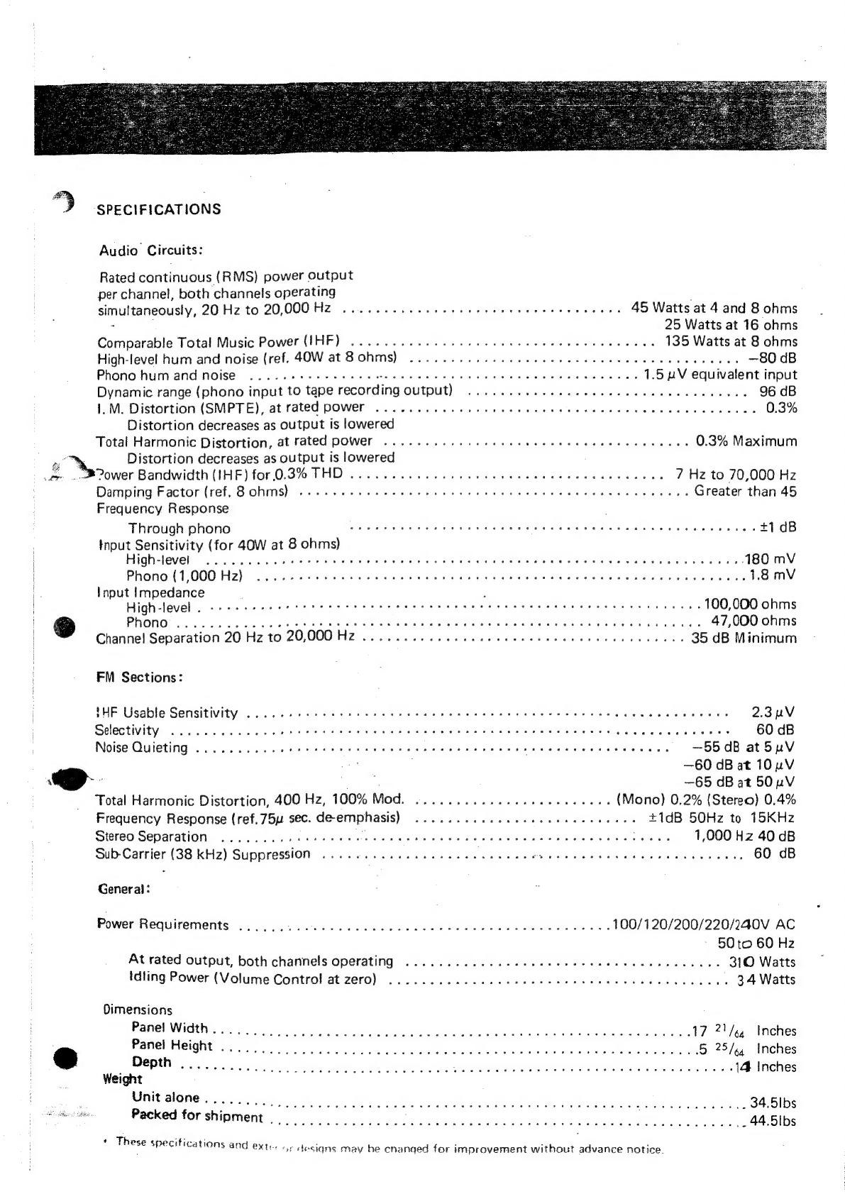
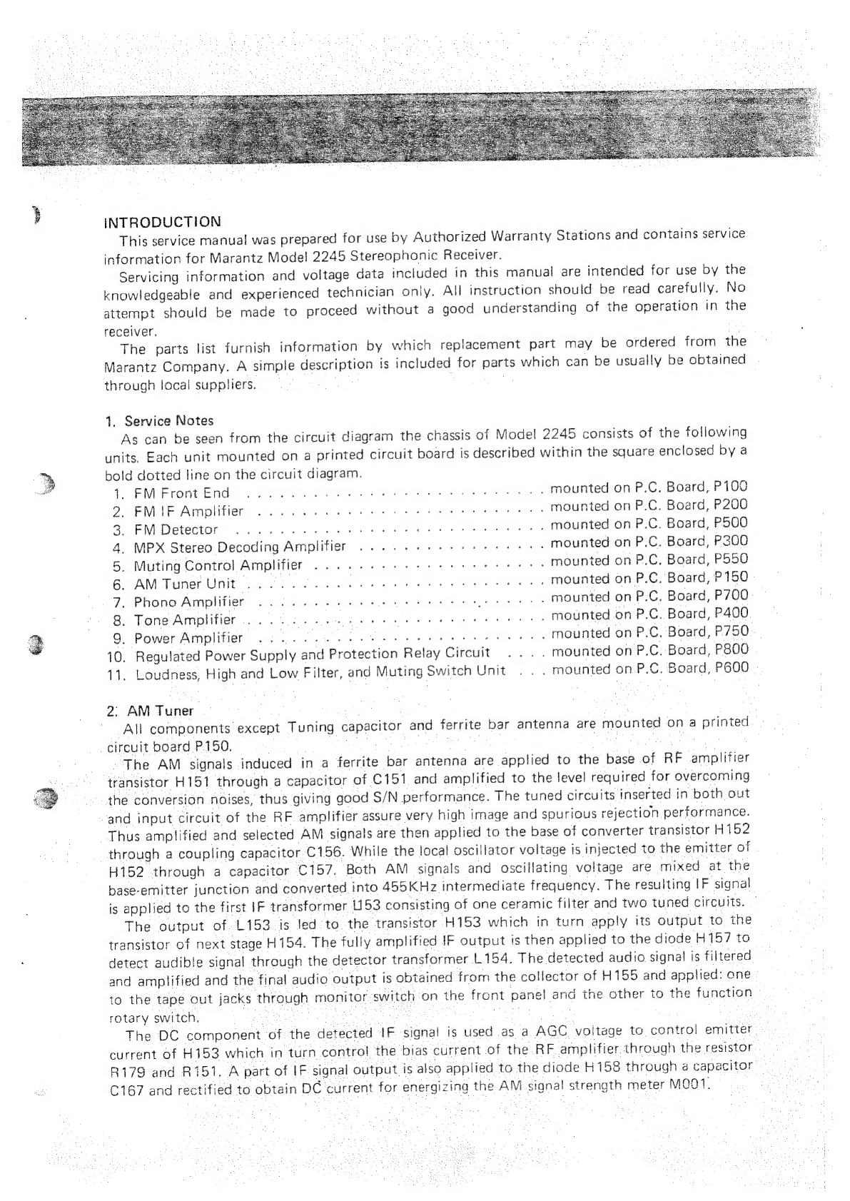
Marantz 2245 User manual
Other Marantz Receiver manuals

Marantz
Marantz AV7005 Quick start guide

Marantz
Marantz SR4320/A1B User manual

Marantz
Marantz SR6005 User manual

Marantz
Marantz 2218 User manual

Marantz
Marantz M-CR510 User manual

Marantz
Marantz SR-6001 User manual

Marantz
Marantz SR880 User manual

Marantz
Marantz SR5008 User guide

Marantz
Marantz SR5023 User manual

Marantz
Marantz Slim-line NR1601 User manual

Marantz
Marantz 2235B User manual

Marantz
Marantz 2270 User manual

Marantz
Marantz SR5400 User manual

Marantz
Marantz SR6006 User manual

Marantz
Marantz Slim-line NR1402 User manual

Marantz
Marantz SR5007 User manual

Marantz
Marantz SR5009 User manual

Marantz
Marantz NR1605 User manual

Marantz
Marantz 2220B User manual

Marantz
Marantz SR5008N User manual