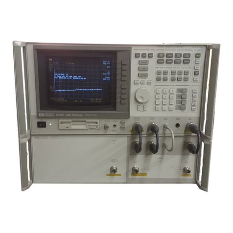
HP 8572A User manual

User's Guide
HP 8572A EMI Receiver
ABCDE
HP P
art No. 08572-90003
Printed in USA April 1992

Notice
The information contained in this do cument is sub ject to change
without notice.
Hewlett-Packard makes no warrantyofany kind with regard to this
material, including, but not limited to, the implied warranties of
merchantability and tness for a particular purpose. Hewlett-Packard
shall not be liable for errors contained herein or for incidental
or consequential damages in connection with the furnishing,
performance, or use of this material.
Restricted Rights Legend.
Use, duplication, or disclosure by the U.S. Government is sub ject to
restrictions as set forth in subparagraph (c) (1) (ii) of the Rights
in Technical Data and Computer Software clause at DFARS
252.227-7013 for DOD agencies, and subparagraphs (c) (1) and (c)
(2) of the Commercial Computer Software Restricted Rights clause at
F
AR 52.227-19 for other agencies.
c
Copyright Hewlett-Packard Company 1992
All Righ
ts Reserv
ed. Reproduction, adaptation, or translation
without prior written permission is prohibited, except as allow
ed
under the cop
yrigh
tla
ws.
1400 F
oun
tain Gro
v
eP
arkw
a
y
, San
ta Rosa, CA 95403-1799, USA

Certification
Hewlett-Packard Company certies that this pro duct met its
published sp ecications at the time of shipment from the factory.
Hewlett-Packard further certies that its calibration measurements
are traceable to the United States National Institute of Standards
and Technology, to the extent allowed by the Institute's calibration
facility, and to the calibration facilities of other International
Standards Organization members.
Warranty
This Hewlett-Packard instrument pro duct is warranted against
defects in material and workmanship for a p erio d of one year from
date of shipment. During the warranty p erio d, Hewlett-Packard
Company will, at its option, either repair or replace pro ducts which
prove to be defective.
For warranty service or repair, this pro duct must b e returned to a
service facilit
ydesignated b
yHewlett-P
ac
k
ard. Buy
er shall prepa
y
shipping c
harges to Hewlett-P
ac
k
ard and Hewlett-Pac
kard shall pa
y
shipping c
harges to return the pro duct to Buy
er. Ho
w
ev
er, Buy
er
shall pa
yall shipping c
harges, duties, and taxes for pro ducts returned
to Hewlett-P
ac
k
ard from another coun
try
.
Hewlett-P
ac
k
ard w
arran
ts that its soft
w
are and rm
w
are designated
b
yHewlett-P
ac
k
ard for use with an instrumen
twill execute
its programming instructions when properly installed on that
instrumen
t. Hewlett-P
ac
k
ard does not w
arran
tthat the operation
of the instrumen
t, or soft
w
are, or rm
w
are will beunin
terrupted or
error-free.
Limit
a
tion of W
arranty
The foregoing w
arran
t
yshall not apply to defects resulting from
improp er or inadequate maintenance byBuyer, Buyer-supplied
software or interfacing, unauthorized mo dication or misuse,
operation outside of the environmental sp ecications for the
pro duct, or improp er site preparation or maintenance.
NO OTHER W
ARRANTY IS EXPRESSED OR IMPLIED.
HEWLETT-P
A
CKARD SPECIFICALL
Y DISCLAIMS THE
IMPLIED W
ARRANTIES OF MER
CHANTABILITY AND
FITNESS F
OR AP
ARTICULAR PURPOSE.
Exclusive Remedies
THE REMEDIES PR
OVIDED HEREIN ARE BUYER'S SOLE
AND EXCLUSIVE REMEDIES. HEWLETT-PACKARD SHALL
NOT BE LIABLE FOR ANY DIRECT, INDIRECT, SPECIAL,
INCIDENT
AL, OR CONSEQUENTIAL D
AMA
GES, WHETHER
BASED ON CONTRACT, TOR
T, OR ANY OTHER LEGAL
THEOR
Y.
iii

Assistance
Product maintenance agreements and other customer assistance
agreements are available for Hew lett-Packardproducts.
For any assistance, contact your nearest Hew lett-Packard Sales and
ServiceOce.
iv

Safety Symbols
The following safety symbols are used throughout this manual.
Familiarize yourself with each of the symbols and its meaning b efore
operating this instrument.
CAUTION
The
CAUTION
sign denotes a hazard. It calls attention to a
pro cedure which, if not correctly p erformed or adhered to, could
result in damage to or destruction of the pro duct or the user's
work. Do not pro ceed b eyond a
CAUTION
sign until the indicated
conditions are fully understo o d and met.
WARNING
The
WARNING
sign denotes a hazard. It calls attention to a
procedure which, if not correctly performed or adhered to, could result
in injury to the user. Do not proceed beyond a
WARNING
sign until
the indicated conditions are fully understood and met.
DANGER
The
DANGER
sign denotes an imminent hazard to people. It warns
the reader of a procedure which, if not correctly performed or adhered
to, could result in injury or loss of life. Do not proceed bey
ond a
D
ANGER
sign until the indicated conditions are fully understood and
met.
v

General Safety Considerations
WARNING
The instructions in this document are for use by qualified personnel
only.Toavoid electrical shock, do not perform any servicing unless
you are qualified to do so.
The opening of covers or removal of parts is likely to expose
dangerous voltages. Disconnect the instrument from all voltage
sources while it is being opened.
The power cord is connected to internal capacitors that may remain
live for five seconds after disconnecting the plug from its power
supply.
This is a Safety Class 1 Product (provided with a protective earthing
ground incorporated in the power cord). The mains plug shall only
be inserted in a socket outlet provided with a protective earth
contact. Any interruption of the protective conductor inside or
outside of the instrument is lik
ely to mak
ethe instrument dangerous.
Intentional interruption is prohibited.
For continued protection against fire hazard, replace fuse only with
same type and ratings, (type nA/nV). The use of other fuses or
materials is prohibited.
W
ARNING
Before this instrument is switched on, mak
esure it has been
properly grounded through the protectiv
econductor of the ac po
w
er
cable to asock
et outlet pro
vided with protectiv
eearthcontact.
Any interruption of the protectiv
e(grounding) conductor, inside or
outside the instrument, or disconnection of the protective earth
terminal can result in personal injury
.
Before this instrument is switched on, make sure its primary power
circuitry has been adapted to the voltage of the ac power source.
Failure to set the ac power input to the correct voltage could cause
damage to the instrument when the ac power cable is plugged in.
vi

In This Book
...
Chapter 1 How and when to calibrate your
EMI receiver system.
Chapter 2 How to perform op eration verication.
Chapter 3 How to set up your test equipment for op eration
verication.
Chapter 4 Howtomaketypical measurements with your
EMI receiver system.
Chapter 5 Howtomake measurements with downloadable
programs.
vii


Contents
1. Calibrating Your Receiver
When to Calibrate Your Receiver . . . . . . . . . 1-2
Calibrating Receiver INPUT 1 and INPUT 2 . . . 1-3
Calibrating Receiver INPUT 3 . . . . . . . . . . 1-5
Preselector Peaking for Receiver INPUT 3 . . . . . 1-7
Correcting Receiver INPUT 3 Using a Calibration
Table . . . . . . . . . . . . . . . . . . . 1-8
Manual Measurements Using Receiver INPUT 3 . 1-11
Automated Measurements Using Receiver INPUT 3 1-12
Spectrum Analyzer Corrected Mo de . . . . . . . 1-14
2. Operation V
erication
Step 1. Set up the hardw
are for operation v
erication
testing .... . ..............2-2
Step 2. Load the soft
w
are ............2-3
Step 3. Select the EMI receiv
er system mo del ...2-5
Step 4. En
ter the EMI receiv
er system test information 2-6
Step 5. Cho ose the output destination for y
our test
results ...................2-7
Step 6. Select \T
est all mo del n
um
bers" ... . . . 2-8
Step 7. Select equipmen
tfrom the UUT Conguration
menu. . .................2-9
Step 8. Assign serial n
um
bers to all equipmen
t...2-10
Step 9. V
erify the test equipmen
t.. . . . . . . . 2-11
Step 10. Conrm the list of accessories . . . . . . 2-12
Step 11. Run the op eration verication tests . . . . 2-13
Optional: Installing the software on an SRM or HFS
hard disk . . . . . . . . . . . . . . . . . . 2-15
Optional: Assigning the address type . . . . . . . 2-16
Optional: Selecting the EMI receiv
er system address 2-17
Optional: Adding option 049 ..... . .....2-18
Optional: Mo difying the temp erature setting . . . 2-19
Optional: Mo difying the h
umidity setting . . . . .2-20
Optional: Selecting the line frequency . . . . . . . 2-21
Optional: Changing the default equipmen
t. . . . . 2-22
Optional: Entering p o
wer sensor calibration factors . 2-26
HP 8572A EMI Receiv
er User's Guide Contents-1

3. Test Descriptions
Calibrator Amplitude Accuracy . . . . . . . . . 3-2
Log Fidelity . . . . . . . . . . . . . . . . . . 3-5
Linear Fidelity. . . . . . . . . . . . . . . . . 3-7
Reference Level Switching Uncertainty . . . . . . 3-9
Receiver Calibration INPUT 1 . . . . . . . . . . 3-12
Amplitude Accy. INPUT 1 (10 dB AT and 0 dB AT) ,
20 Hz-9 kHz . . . . . . . . . . . . . . . . 3-15
Amplitude Accy. INPUT 1 (10 dB AT and 0 dB AT) 3-17
Disp. Average Noise INPUT 1 . . . . . . . . . . 3-19
Sensitivity INPUT 1, 20 Hz to 9 kHz . . . . . . . 3-21
Residual Responses INPUT 1 . . . . . . . . . . 3-23
Bandwidth Accuracy . . . . . . . . . . . . . . 3-25
Pulse Response . . . . . . . . . . . . . . . . . 3-28
Calibration INPUT 2 . . . . . . . . . . . . . . 3-33
Amplitude Accy. INPUT 2 (10 dB AT and 0 dB AT) 3-36
Disp. Average Noise INPUT 2 . . . . . . . . . . 3-39
Residual Responses INPUT 2 . . . . . . . . . . 3-41
Amplitude Accy
. INPUT 3 . ..........3-43
Disp. Av
erage Noise INPUT 3,10 Hz RBW ....3-48
Residual Responses INPUT 3......... . 3-50
4. Making T
ypical Measuremen
ts
T
esting for Ov
erload ..... . ........4-1
3dB Linearity Chec
k.............4-2
Narrowband/Broadband Signals .........4-2
Commercial Compliance Measuremen
ts ......4-5
Detector Selection ..... . ........4-5
Measuremen
t Examples ............4-9
CE03 (MIL-STD) Measuremen
t.........4-23
RE02 (MIL-STD) Measuremen
t.........4-26
CISPR 22 Measuremen
ts ...... . . . . . .4-28
5. Downloadable Program (DLP) Measurements
Example: Quasi-p eak measurements on broadband
signals, using a DLP . . . . . . . . . . . . . 5-1
Index
Contents-2 HP 8572A EMI Receiv
er User's Guide

Figures
1-1. Sample Calibration Table . . . . . . . . . . . 1-9
1-2. Calibration Data Graph . . . . . . . . . . . . 1-13
4-1. Testing for Overload . . . . . . . . . . . . . 4-1
4-2. Narrowband Sp ectrum . . . . . . . . . . . . 4-2
4-3. Broadband Sp ectrum . . . . . . . . . . . . . 4-3
4-4. Metho ds for Narrowband and Broadband Analysis 4-4
4-5. Signal Detection and Pro cessing . . . . . . . . 4-6
4-6. Average Detection Using Video Filtering . . . . 4-7
4-7. Quasi-Peak Detection . . . . . . . . . . . . . 4-8
4-8. Quasi-Peak Detector Output . . . . . . . . . . 4-9
4-9. P
eak Measuremen
tof aCWSignal . . . . . ..4-12
4-10. Peak Measurement of a Broadband Signal ....4-14
4-11. Quasi-P
eak Measuremen
tof aCW Signal ....4-18
4-12. Quasi-P
eak Measuremen
tof aBroadband Signal .4-20
4-13. Comp osite Signal .......... . . . ..4-21
4-14. Av
erage Measuremen
t.... . ........4-23
4-15. CE03 P
o
w
er Lead T
est Setup (Air F
orce and Na
vy) 4-24
4-16. Curren
tProb es as T
ransducers .........4-25
4-17. Bandwidth Correction F
actor ........ . 4-26
4-18. RE02 T
est Setup . . .............4-27
4-19. Characteristic Appearance of Radiated Emissions .4-30
4-20. Equipmen
tUnder T
est (EUT) T
urned O ....4-30
5-1. Quasi-P
eak Measuremen
tUsing the HP 85867A DLP 5-3
Tables
1-1. F
requency Bands .......... . ....1-7
1-2. receiv
er INPUT 3F
requency Bands .......1-10
2-1. T
est Equipmen
t . . . . . . . . . . . . . . . 2-23
2-2. T
est Equipmen
tV
ariable Names . . . . . . . . 2-24
HP 8572A EMI Receiv
er User's Guide Contents-3

1
Calibrating Your Receiver
In this chapter, you'll learn how and when to calibrate your
HP 8572A microwave EMI receiver:
how often to calibrate your receiver
how to calibrate receiver INPUT 1 and receiver INPUT 2
how to calibrate receiver INPUT 3
how to p erform preselector p eaking for receiver INPUT 3
how use a calibration table to calibrate receiver INPUT 3
ho
wto perform man
ual and automated measuremen
ts
HP 8572A EMI Receiv
er User's Guide Calibrating Y
our Receiv
er 1-1

When to Calibrate Your Receiver
Note
To meet specied absolute amplitude accuracy,your receiver must
be calibrated. For accurate calibration, ambient temp erature must
be 20 to 30 degrees centigrade. Your receiver must b e stabilized at
ro om temperature for at least two hours, to allo w comb amplitude
to stabilize.
Calibrate your HP 8572A microwave EMI receiver:
at the start of eachday
after power is cycled on the RF preselector
for eachchange in:
resolution bandwidth
frequency band
spectrum analyzer or preselector atten
uation
logarithmic/linear scale
AMPTD CAL setting
In addition to these calibrations, y
ou also should v
erify the
performance of the HP 8572A micro
w
a
v
eEMI receiv
er perio dically
.
Complete RF preselector com
bc
haracterization and all EMI
receiv
er system performance tests ev
ery six mon
ths to be sure the
EMI receiv
er system con
tinues to meet its specications. During
performance testing, use the en
tire EMI receiv
er system (including all
cables).
This perio dic calibration requires extensiv
etest equipmen
t,
and can betime consuming. F
or y
our con
venience, calibration
and performance v
erication is av
ailable through y
our lo cal
Hewlett-Packard service center.
1-2 Calibrating Y
our Receiv
er HP 8572A EMI Receiv
er User's Guide

Calibrating Receiver INPUT 1 and INPUT 2
Note
Receiver INPUT 1 and receiver INPUT 2 are input 1 and input 2
on the HP 85685A RF preselector.
When calibrating receiver INPUT 1 and receiver INPUT 2,
complete the pro cedure for each new combination of frequency
range, resolution bandwidth, logarithmic/linear scale, and
attenuation settings.
To calibrate receiver INPUT 1 and receiver INPUT 2:
1. Connect the 100 MHz CAL OUTPUT on the sp ectrum analyzer
to receiver INPUT 2 on the RF preselector.
2. On the quasi-p eak adapter, select the bypass path by pressing
the BYPASS key in the INSTR FUNCTION group. The LED
abo
v
ethat k
ey will ligh
t.
3. On the RF preselector
,select the b
ypass path b
y pressing the
ENABLE
4
5
k
ey and the BYP
ASS
4
5
k
ey; the BYP
ASS LED
near receiv
er INPUT 2will ligh
t.
4. Select the preamplier b
ypass path b
ypressing the
SWITCHES 0
4
5
k
ey on the atten
uator/switc
hdriv
er; the LED
in that k
ey will ligh
t.
5. Press
4
RECALL
54
8
5
on the spectrum analyzer.
6. Adjust AMPTD CAL on the spectrum analyzer for
0
10 dBm
6
0.20 dB
.
7. Press
4
RECALL
54
9
5
on the spectrum analyzer.
8. Adjust FREQ ZER
Oon the sp ectrum analyzer for amaxim
um
signal on the display.
9. Select the frequency range, resolution bandwidth,
logarithmic/linear scale, and attenuator settings to b e used for
the desired measurement.
10. Select the quasi-p eak adapter bandwidth for the measuremen
t.
11. Connect the COMB GENERA
TOR OUTPUT on the
RF preselector to the receiv
er input to b e calibrated.
12. Execute the com
b calibration sequence b
y pressing CAL SEQ
4
START
5
on the RF preselector
.
If the start frequency is belo
w200
kHz, the sp ectrum analyzer will
display the 100 kHz comb signal and you will b e instructed to adjust
AMPTD CAL on the sp ectrum analyzer for the displayed amplitude
of the 100 kHz com
bto oth to within
6
0.2 dB.If the 100 kHz
calibration signal amplitude is within
6
0.2 dB of the desired v
alue,
no adjustmen
tis necessary; the calibration sequence will con
tin
ue
automatically
.
HP 8572A EMI Receiv
er User's Guide Calibrating Y
our Receiv
er 1-3

After adjusting AMPTD CAL to within
6
0.2 dB, press
CAL SEQ
4
START
5
on the RF preselector to continue the calibration
routine. If the stop frequency is ab ove 200 kHz , the calibration
sequence is performed over the frequency span ab ove200kHz.
The comb generator CAL SEQ LED ashes while the calibration
sequence is running. When the calibration sequence ends, the CAL
SEQ LED stays on, indicating that the system is calibrated over the
current frequency range. If the receiver frequency is increased b eyond
the calibrated frequency range, the CAL SEQ LED turns o, to
indicate an uncalibrated state.
Note
The CAL SEQ LED do es not turn o when settings other than
start or stop frequency are changed. Therefore, it is p ossible for an
uncalibrated state to exist for the current settings of resolution
bandwidth, attenuation, or amplitude scale while the CAL SEQ
LED is turned on.
Be sure the receiver is calibrated for the current
instrument settings.
If y
ou c
hange resolution bandwidth, logarithmic/linear scale, or
atten
uation, or readjust AMPTD CAL, rep eat steps 9 through 12
with the new settings.
1-4 Calibrating Y
our Receiv
er HP 8572A EMI Receiv
er User's Guide
Calibrating Receiver INPUT 3
Note
Receiver INPUT 3 is the preamplier input on the HP 8449B Opt
H02 preamplier.
When calibrating receiver INPUT 3 ,
Complete the calibration pro cedure for frequency range,
resolution bandwidth, logarithmic/linear scale, and attenuation
settings.
Apply amplitude correction factors from the calibration table on
page 1-10.
Execute a PRESEL PEAK (preselector peak) for eachsignal in
preselected band 1 through band 4 (2 GHz to 22 GHz).
To calibrate receiver INPUT 3 :
1. Connect the 100 MHz CAL OUTPUT on the sp ectrum analyzer
to receiv
er INPUT 2.
2. On the RF preselector
,select the bypass path b
ypressing the
ENABLE
4
5
k
ey and the BYP
ASS
4
5
k
ey; the BYP
ASS LED
near receiv
er INPUT 2willligh
t.
3. Select the preamplier b
ypass path b
ypressing the
SWITCHES 0
4
5
k
ey on the atten
uator/switc
hdriv
er; the LED
in that k
ey will ligh
t.
4. Press
4
RECALL
54
8
5
on the spectrum analyzer.
5. Select the resolution bandwidth and logarithmic/linear scale
settings for the measuremen
t.
6. Adjust AMPTD CAL on the sp ectrum analyzer for
0
10 dBm
6
0.20 dB.
7. Press
4
RECALL
54
9
5
on the sp ectrum analyzer.
8. Adjust FREQ ZERO on the sp ectrum analyzer for maximum
trace amplitude.
9. Press the SWITCHES 0
4
5
k
ey on the atten
uator/switc
hdriv
er
until the LED turns o.
10. Press
4
SHIFT
54
PRESEL PEAK
5
on the sp ectrum analyzer.
11. T
o correct for receiv
er frequency resp onse, subtract the gain
factor from the displa
yed signal amplitude. See \Correcting
Receiver INPUT 3 Using a Calibration Table").
Steps 1 through 6 p erform a modied
4
RECALL
54
8
5
amplitude
adjustmen
tthrough the b
ypass path. Pressing
4
SHIFT
54
PRESEL PEAK
5
in step 10 will optimize 2GHz to 22 GHz RF preselector lter
trac
king for best o
v
erall response. T
oobtain true signal amplitude,
complete a
4
PRESEL PEAK
5
for eac
hsignal.
HP 8572A EMI Receiv
er User's Guide Calibrating Y
our Receiv
er 1-5

Note
If you change resolution bandwidth, or logarithmic/linear scale
settings, or readjust AMPTD CAL on the sp ectrum analyzer,
repeat this pro cedure with the new settings.
1-6 Calibrating Y
our Receiv
er HP 8572A EMI Receiv
er User's Guide

Preselector Peaking for Receiver INPUT 3
To obtain the specied absolute amplitude accuracy for the 2 GHz
to 22 GHz frequency bands, the tracking preselector must be
peaked for each signal. If this is not done, displayed signals above
2 GHz are likely to be displayed as much as 5 dB to 7 dB lower.
This discrepancy could cause amplitude errors of
0
0.7 to
0
1dB,
which b ecomes signicantgiven the
6
2 dB amplitude accuracy
specication.
To determine the true amplitude of a signal, place the marker on the
peak of the signal and press
4
PRESEL PEAK
5
. The sp ectrum analyzer
automatically ne tunes its preselector lter, using a digital-to-analog
converter (DAC), for maximum signal amplitude, so the signal is not
attenuated by the lter skirts.
Use the factory-default preselector DAC setting of 32 (obtained by
executing
4
SHIFT
54
PRESEL PEAK
5
) for b est overall frequency response
when viewing an en
tire sw
ept frequency band.
Because the relativ
etuning of the preselector lter c
hanges at
dieren
tpoin
ts in an
ygiv
en frequency span, the optimum preselector
peak D
A
Cv
alue can dier b
ysev
eral D
A
Cn
um
bers, for dieren
t
frequencies in agiven frequency span, causing as m
uc
has 1dB
amplitude error. T
oa
v
oid this, execute
4
PRESEL PEAK
5
at eac
h
frequency of in
terest.
T
able 1-1. Frequency Bands
F
requency
Band
F
requency
Range n
YTO
F
requency
Range
0A
1
0.0{2.5 GHz 13.62{6.12
GHz
1 B 2.0{5.8 GHz 1 2.32{6.12
GHz
2 C 5.8{12.5
GHz
2 2.74{6.09
GHz
3D12.5{18.6
GHz
34.06{6.09
GHz
4E 18.6{22.0
GHz
44.57{5.42
GHz
1
Low Band (preselector p eaking is not required).
HP 8572A EMI Receiv
er User's Guide Calibrating Y
our Receiv
er 1-7

Correcting Receiver INPUT 3 Using a Calibration Table
To obtain sp ecied absolute amplitude accuracy for signals
measured through receiver INPUT 3, apply the frequency-dep endent
correction factors to signal amplitude measurements. Because of the
preamplier gain, signals will be displayed on the receiver displayat
an amplitude higher than the actual signal amplitude.
Figure 1-1 is a sample calibration table. The calibration data corrects
for preamplier gain, preamplier frequency resp onse, and spectrum
analyzer frequency resp onse for b oth 0 dB and 10 dB sp ectrum
analyzer attenuation after the receiver calibration routine has b een
completed. Calibration factors are provided every 50 MHz from
1.0 GHz to 22 GHz for each frequency band.
Calibration data is provided in two forms in the calibration table:
gain in dB, and correction factor with a specic reference level oset.
1-8 Calibrating Y
our Receiv
er HP 8572A EMI Receiv
er User's Guide
Other manuals for 8572A
1
Other HP Receiver manuals

HP
HP X5400 Installation and maintenance instructions

HP
HP 8542E User manual

HP
HP 8530A User manual

HP
HP x280n - MediaSmart Connect - Digital Multimedia... Use and maintenance manual

HP
HP x280n - MediaSmart Connect - Digital Multimedia... Installation and operation manual

HP
HP Hewlett-Packard User manual

HP
HP 8542E Installation and operation manual

HP
HP 8530A User manual

HP
HP x280n - MediaSmart Connect - Digital Multimedia... User manual

HP
HP EN5000 Instruction Manual