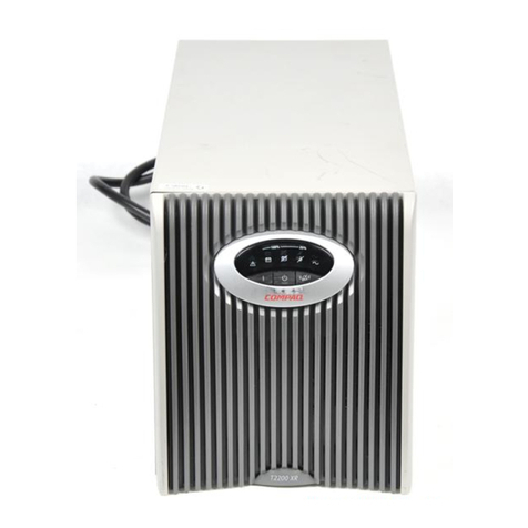
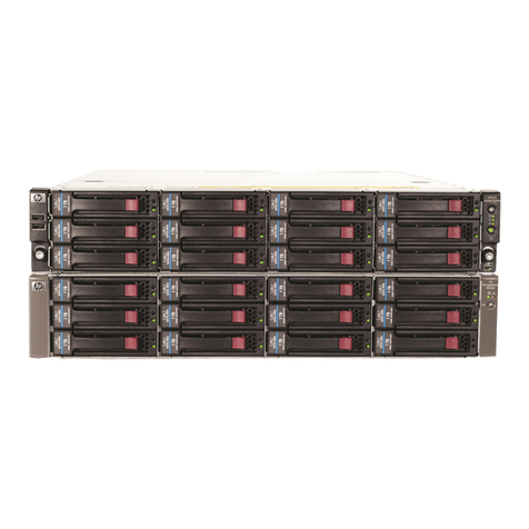
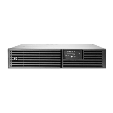
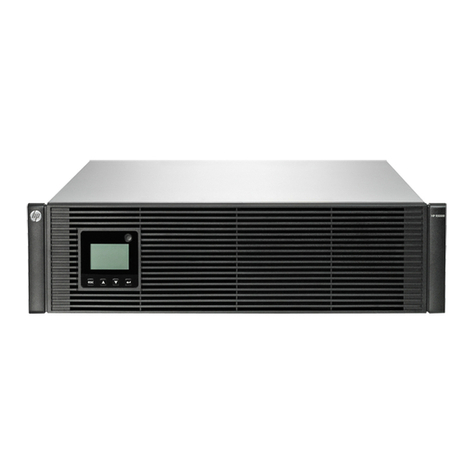
HP R12000 XR User manual

HP R12000 and R18000 DirectFlow UPS
User Guide
Abstract
This document includes installation, configuration, and operation information for the HP R12000 and R18000 DirectFlow UPS. Th
is document is for
the person who installs and maintains power products. HP assumes you are qualified in the servicing of high-voltage equipment and trained in
recognizing hazards in products with hazardous energy levels.
Part Number: 709321-003
April 2015
Edition: 3

© Copyright 2014, 2015 Hewlett-Packard Development Company, L.P.
The information contained herein is subject to change without notice. The only warranties for HP products and services are set forth in the express
warranty statements accompanying such products and services. Nothing herein should be construed as constituting an additional warranty. HP shall
not be liable for technical or editorial errors or omissions contained herein.
Links to third-party websites take you outside the HP website. HP has no control over and is not responsible for information outside HP.com.
Confidential computer software. Valid license from HP required for possession, use or copying. Consistent with FAR 12.211 and 12.212,
Commercial Computer Software, Computer Software Documentation, and Technical Data for Commercial Items are licensed to the U.S. Government
under vendor’s standard commercial license.
Microsoft®, Windows®, and Windows Server® are trademarks of the Microsoft group of companies.

Contents 3
Contents
Overview..................................................................................................................................... 6
HP DirectFlow UPS overview....................................................................................................................... 6
Power management options .............................................................................................................. 6
Advanced monitoring and management features ................................................................................. 7
Location Discovery Services for the UPS configuration .......................................................................... 7
REPO port ...................................................................................................................................... 8
Component identification ........................................................................................................................... 8
HP R12000 DirectFlow UPS.............................................................................................................. 8
HP R18000 DirectFlow UPS............................................................................................................ 11
1U battery pack rear panel............................................................................................................. 14
3U battery pack rear panel............................................................................................................. 15
Power unit and battery pack configurations ................................................................................................ 15
Installation ................................................................................................................................. 18
Precautions............................................................................................................................................. 18
Important device safety information.................................................................................................. 18
Preparing to install the hardware............................................................................................................... 19
Tools and materials........................................................................................................................ 19
Selecting a site.............................................................................................................................. 19
Readying the equipment ................................................................................................................. 20
Installing rack rails .................................................................................................................................. 20
Installing rack rails for the 1U power unit.......................................................................................... 20
Installing rack rails for the 2U power unit.......................................................................................... 23
Installing rack rails for the 1U battery pack ....................................................................................... 26
Installing rack rails for the 3U battery pack ....................................................................................... 29
Installing battery packs............................................................................................................................. 33
Powering down the UPS ................................................................................................................. 33
Installing the 1U battery pack.......................................................................................................... 33
Installing the 3U battery pack.......................................................................................................... 39
Installing the power unit ........................................................................................................................... 47
Installing the R12000DF power unit ................................................................................................. 47
Installing the R18000DF power unit ................................................................................................. 52
Connecting the UPS to utility power ................................................................................................. 56
Connecting devices ....................................................................................................................... 57
Starting power to the load .............................................................................................................. 57
Continuing the installation of components ......................................................................................... 57
Installing the Management Module card..................................................................................................... 57
Installing the Management Module card in the 1U power unit ............................................................. 58
Installing the Management Module card in the 2U power unit ............................................................. 60
Checking the Health/Alert LED........................................................................................................ 62
Configuration ............................................................................................................................. 63
Accessing the Management Module .......................................................................................................... 63
Launching a terminal emulation program .......................................................................................... 63
Launching a telnet session............................................................................................................... 64
Navigating the Service Menu.................................................................................................................... 64
Service Menu................................................................................................................................ 65

Contents 4
Module Configuration submenu....................................................................................................... 65
Configuring the Management Module card for remote access....................................................................... 70
Launching a web browser............................................................................................................... 71
Signing into the Management Module web interface.......................................................................... 71
Configuring the power unit....................................................................................................................... 72
UPS operations........................................................................................................................... 73
Navigating UPS menu options .................................................................................................................. 73
UPS menu options.......................................................................................................................... 73
Configuring the battery charge power levels ..................................................................................... 75
Changing the language.................................................................................................................. 76
Working with UPS modes of operation....................................................................................................... 76
AC mode ..................................................................................................................................... 76
Battery mode ................................................................................................................................ 77
Bypass mode ................................................................................................................................ 77
Maintenance.............................................................................................................................. 78
Updating the UPS firmware ...................................................................................................................... 78
Restoring power after a REPO activation .................................................................................................... 79
Verifying the REPO port connection ........................................................................................................... 79
Powering down the UPS and battery packs................................................................................................. 80
Replacing the batteries............................................................................................................................. 80
Important battery safety information ................................................................................................. 80
Battery care and storage guidelines ................................................................................................. 80
Battery replacement procedure........................................................................................................ 81
Replacing the 1U battery pack .................................................................................................................. 83
Replacing the 3U battery pack .................................................................................................................. 84
Replacing the Management Module card ................................................................................................... 85
Replacing the power module .................................................................................................................... 85
Replacing the 1U power unit..................................................................................................................... 86
Replacing the 2U power unit..................................................................................................................... 87
Troubleshooting .......................................................................................................................... 89
LED and audible alarm troubleshooting ...................................................................................................... 89
Alarm descriptions and SNMP trap codes......................................................................................... 90
General alarm condition .......................................................................................................................... 92
UPS does not start ................................................................................................................................... 93
Wiring condition..................................................................................................................................... 93
Utility power condition ............................................................................................................................. 93
Battery connection condition ..................................................................................................................... 93
REPO condition....................................................................................................................................... 94
UPS is in Bypass mode............................................................................................................................. 94
Overload condition ................................................................................................................................. 94
UPS is in Battery mode............................................................................................................................. 95
UPS frequently switches between utility and battery power............................................................................ 95
Battery fault ............................................................................................................................................ 95
UPS backup time is short .......................................................................................................................... 95
Low battery shutdown .............................................................................................................................. 95
Deep Sleep mode.................................................................................................................................... 95
UPS alarm code decision flowcharts .......................................................................................................... 97
Specifications........................................................................................................................... 112
Environmental specifications ................................................................................................................... 112
Power unit physical specifications............................................................................................................ 112
REPO port specifications............................................................................................................... 112

Contents 5
Battery pack physical specifications ......................................................................................................... 112
1U battery pack specifications ...................................................................................................... 113
3U battery pack specifications ...................................................................................................... 113
Lead acid battery module specifications ......................................................................................... 113
Lithium-ion battery module specifications......................................................................................... 113
Battery runtime ............................................................................................................................ 114
UPS input specifications ......................................................................................................................... 114
UPS output specifications........................................................................................................................ 115
Voltage specifications .................................................................................................................. 115
Output tolerance specifications...................................................................................................... 115
Output feature specifications ......................................................................................................... 115
Spares..................................................................................................................................... 116
UPS spare parts list................................................................................................................................ 116
R12000DF UPS spare parts list ..................................................................................................... 116
R18000DF UPS spare parts list ..................................................................................................... 116
Hardware options ................................................................................................................................. 117
Electrostatic discharge............................................................................................................... 118
Preventing electrostatic discharge ............................................................................................................ 118
Grounding methods to prevent electrostatic discharge................................................................................ 118
Regulatory information .............................................................................................................. 119
Safety and regulatory compliance ........................................................................................................... 119
Turkey RoHS material content declaration................................................................................................. 119
Ukraine RoHS material content declaration ............................................................................................... 119
Warranty information ............................................................................................................................ 119
Support and other resources ...................................................................................................... 120
Before you contact HP............................................................................................................................ 120
HP contact information........................................................................................................................... 120
HP product QuickSpecs.......................................................................................................................... 120
Documentation feedback ........................................................................................................... 121
Acronyms and abbreviations...................................................................................................... 122
Index....................................................................................................................................... 124

Overview 6
Overview
HP DirectFlow UPS overview
The HP DirectFlow UPS features a configurable rack-mount design that offers three-phase power protection
for loads up to a maximum of 20000 VA/18000 W (these numbers might vary by model). Features include:
•Configurations for extending runtime
oA configurable power unit with the following rack unit heights:
—R12000DF—1U
—R18000DF—2U
oOptional 3U lead acid or 1U lithium-ion battery packs
oA minimum of 60 seconds of backup power with one battery pack and 5 minutes of backup power
with two battery packs provided for the maximum load
•Advanced battery management to increase battery service life and optimize recharge time
oWarning before the end of the useful battery life
oEasily replaceable battery modules that simplify maintenance
•Configurable utility and generator battery charge power level switching
•Optional HP DirectFlow UPS Management Module network connectivity with advanced remote
monitoring, control, and management features
•Built-in location awareness of components
•Emergency shutdown control through a REPO port
•Firmware that is service upgradeable through a standard DB-9 serial communication port
•Backed by worldwide agency approvals
To benefit from product enhancements, update to the latest versions of UPS firmware and software. To
download the UPS firmware and software, see the HP website (http://www.hp.com/go/rackandpower).
Power management options
The DirectFlow UPS is comprised of an HP DirectFlow Power Unit configured with either HP DirectFlow VRLA
Battery Packs (3U) or an R12000DF (1U) or R18000DF (3U) HP DirectFlow Lithium-ion Battery Pack.
The DirectFlow UPS works within an overall power management plan that can include utility, generator, and
battery power.
The power unit includes front panel controls and an LCD screen for navigating UPS menu options (on page
73) to access system values. Certain values can be configured to accommodate your power management
plan.
Each battery pack provides a minimum of 60 seconds of backup power as a stopgap for a power supply lag
or outage. Depending upon configuration, including the number of battery packs and load requirements, the

Overview 7
UPS can extend backup power for an increased amount of time. Distribute the load as evenly as possible
across the UPS configuration to most efficiently use the powerful three-phase UPS design.
The UPS modes of operation allow the UPS to transfer seamlessly between AC, Battery, and Bypass modes
to supply power to connected devices without interruption. For more information, see "Working with UPS
modes of operation (on page 76)." The power unit can use a built-in, time-based algorithm to switch between
utility and generator battery charging power levels when transferring operating modes. Using a lower
charge level while the UPS runs on generator power maximizes the output available to connected devices.
The Management Module provides additional features to receive generator commands. To set UPS battery
charge power levels, see "Configuring the battery charge power levels (on page 75)."
Advanced monitoring and management features
The Management Module card reports detailed information to the Management Module web interface
where the information is graphically displayed. Many commands and functions can be customized from the
interface. Customizable setup options in the UPS Service Menu can also be accessed using the Management
Module card. The Management Module is designed specifically for the DirectFlow UPS. It is not intended for
installation in other UPS devices.
To install and initially configure the Management Module in the DirectFlow UPS, see "Installing the
Management Module card (on page 57)" and "Accessing the Management Module (on page 63)." For
details about using the Management Module card and web interface, see the HP DirectFlow UPS
Management Module User Guide on the HP website (http://www.hp.com/support/DFUPS_MM_UG_en).
Location Discovery Services for the UPS configuration
HP provides built-in location awareness of rack components, a capability that works hand-in-hand with
technology in the new HP Intelligent Series racks. Together, the technologies provide the rack identification
number and precise U location of the components. This information is communicated through power
management software.
HP R12000DF

Overview 8
HP R18000DF
When the power unit is fully seated within the rack, Discovery Services connectors meet with a rack-mounted
EEPROM strip. Discovery Services reports the specific location of the power unit and a calculated location of
any battery packs. The battery packs must be installed directly beneath the power unit in the rack, without a
U gap, for Discovery Services to locate them. Racks without pre-installed EEPROM strips may be upgraded
by ordering and installing the strips, available on the HP website
(http://www.hp.com/products/rackoptions).
REPO port
The power unit includes an isolated REPO port. When properly wired, the REPO feature enables the power
at the UPS output receptacles to be switched off from a remote location. To use this feature, the REPO port
must be connected to a remote, normally open switch (not supplied). The REPO switch is used in conjunction
with a main disconnect device that removes the AC source from the input of the power unit.
When the switch is closed:
•The REPO feature immediately powers down protected devices and does not utilize an orderly
shutdown procedure.
•The REPO feature shuts down power units operating under utility, generator, or battery power.
To connect a REPO port, see either "Connecting the R12000DF REPO port (on page 49)" or "Connecting the
R18000DF REPO port (on page 54)." To restore power to the load devices after the REPO feature has been
activated, see "Restoring power after a REPO activation (on page 79)."
Component identification
HP R12000 DirectFlow UPS
The components in the following sections are found in the HP R12000 DirectFlow UPS.

Overview 9
Power unit front panel controls
Item Component Description
1 UPS fault LED Red light indicates a fault; no light indicates proper
function.
2 Bypass mode LED Green light indicates Bypass mode; no light
indicates AC mode.
3 Battery mode LED Yellow light indicates Battery mode; flashing
indicates low battery.
4 Input LED Green light indicates that the power input is
adequate.
5
Up arrow
Press to scroll up through the menu structure.
6 Down arrow Press to scroll down through the menu structure.
7 Off/ESC/Clear fault
button
•
In AC mode, press the button for 3 seconds to
transfer the UPS to Bypass mode; in Battery
mode, press for 3 seconds to shut down the UPS
output.
•
During menu selection, press the button to go
back to the previous menu.
•
During a UPS fault, press the button for 3
seconds to clear the fault and transfer the UPS
to Bypass mode.
8 On/Enter button Press the button for 3 seconds to turn the UPS on;
press the button to confirm setup or menu entries.

Overview 10
Power unit rear panel
Item Description
1 Cover plate for option slot
2 REPO port
3 DB-9 serial port for flashing UPS firmware
4
DB-15 port for a CAN Bus cable for battery pack
communication
5 Power cable for connection to the battery pack
6 Input/output power module connection
7 Input/output power module connection
Power unit rear panel with components

Overview 11
Item Description
1 HP DirectFlow UPS Management Module card
2 HP DirectFlow Input/Output Power Module switch
3 HP DirectFlow Input/Output Power Module connection
and cables
Power unit rear panel with Management Module card
Item Description
1 RJ-45 for network or Ethernet communications
2 DB-9 serial port for configuration and flashing card
firmware
3 Power LED
4 Health/Alert LED
HP R18000 DirectFlow UPS
The components in the following sections are found in the HP R18000 DirectFlow UPS.

Overview 12
Power unit front panel controls
Item Component Description
1 UPS fault LED Red light indicates a fault; no light indicates proper
function.
2 Bypass mode LED Green light indicates Bypass mode; no light
indicates AC mode.
3 Battery mode LED Yellow light indicates Battery mode; flashing
indicates low battery.
4 Input LED Green light indicates that the power input is
adequate.
5
Up arrow
Press to scroll up through the menu structure.
6 Down arrow Press to scroll down through the menu structure.
7 Off/ESC/Clear fault
button
•
In AC mode, press the button for 3 seconds to
transfer the UPS to Bypass mode; in Battery
mode, press for 3 seconds to power down the
UPS output.
•
During menu selection, press the button to go
back to the previous menu.
•
During a UPS fault, press the button for 3
seconds to clear the fault and transfer the UPS
to Bypass mode.
8 On/Enter button Press the button for 3 seconds to power up the UPS
on; press the button to confirm setup or menu
entries.

Overview 13
Power unit rear panel
Item Description
1 Cover plate for option slot
2 REPO port
3 DB-9 serial port for flashing UPS firmware
4
DB-15 port for a CAN Bus cable for battery pack
communication
5 Power cable for connection to the battery pack
6 Input/output power module connection
7 Input/output power module connection
Power unit rear panel with components

Overview 14
Item Description
1 HP DirectFlow UPS Management Module card
2 HP DirectFlow Input/Output Power Module switch
3 HP DirectFlow Input/Output Power Module connection
and cables
Power unit rear panel with Management Module card
Item Description
1 Power LED
2 Health/Alert LED
3 DB-9 serial port for configuration and flashing card
firmware
4 RJ-45 for network or Ethernet communications
1U battery pack rear panel
Item Description
1 Connection for a DC to DC power cable to the power unit
2 Circuit breaker switch

Overview 15
Item Description
3 Connection for a DC to DC power cable to the battery
pack
4 DB-15 ports for CAN Bus cables for battery pack
communication
3U battery pack rear panel
Item Description
1 Connection for a DC to DC power cable to the power unit
2 Connection for a DC to DC power cable to the battery
pack
3 DB-15 ports for CAN Bus cables for battery pack
communication
4 Circuit breaker switch
Power unit and battery pack configurations
The DirectFlow UPS can be configured in the following ways:
•DirectFlow power unit without any battery packs
The power unit can work as a standalone line conditioner, or active filter, that mitigates harmonics and
power factor for the input AC line that supplies utility or generator power. To set the power unit active
current correction (ACC) options, see the "UPS menu options (on page 73)."
A configuration without battery packs does not supply power for extended runtime.
•DirectFlow power unit with one battery pack

Overview 16
o3U DirectFlow Battery Pack
o1U DirectFlow Battery Pack
•DirectFlow power unit with two battery packs in series
The battery packs must be the same rack unit height and battery type; for instance, the power unit could
connect to a 3U lead acid battery pack connected in series to a 3U lead acid battery pack.

Overview 17
oTwo 3U DirectFlow Battery Packs
oTwo 1U DirectFlow Battery Packs

Installation 18
Installation
Precautions
See the complete regulatory compliance notices in Safety and Compliance Information for Server, Storage,
Power, Networking, and Rack Products on the HP website
(http://www.hp.com/support/Safety-Compliance-EnterpriseProducts). In addition, follow the safety
precautions that are specific to this device.
Save these instructions. This document contains important safety instructions that should be followed during
installation, operation, and maintenance of the UPS and batteries.
This symbol indicates that the power unit exceeds the recommended weight for one
individual to handle safely. Weight for each power unit is:
•R12000DF—16 kg (35.2 lb)
•R18000DF—20.87 kg (46 lb)
WARNING: To reduce the risk of personal injury or damage to the equipment, observe
local occupational health and safety requirements and guidelines for manual material
handling.
100 kg
220 lb
This symbol indicates that the 3U DirectFlow Battery Pack exceeds the recommended
weight for one individual to handle safely.
WARNING: To reduce the risk of personal injury or damage to the equipment, observe
local occupational health and safety requirements and guidelines for manual material
handling.
12 kg
26.5 lb
This symbol indicates that the 1U DirectFlow Battery Pack exceeds the recommended
weight for one individual to handle safely.
WARNING: To reduce the risk of personal injury or damage to the equipment, observe
local occupational health and safety requirements and guidelines for manual material
handling.
WARNING: A risk of personal injury or damage to the equipment exists. Uneven loading of
equipment in the rack might cause the rack to become unstable. Install the heavier components
first, and then continue to populate the rack from the bottom to the top.
WARNING:
A risk of personal injury from electric shock and hazardous energy levels exists. The
installation of options and routine maintenance and service of this product must be performed by
individuals who are knowledgeable about the procedures, precautions, and hazards associated
with AC power products.
WARNING: Contact with any part of a grounded battery can result in electrical shock. Shock risk
is reduced if grounds are removed during installation and maintenance.
Important device safety information

Installation 19
WARNING: To reduce the risk of fire, only connect unit input to a circuit provided with branch
circuit overcurrent protection for 30 A rating in accordance with the National Electric Code,
ANSI/NFPA 70.
Disconnect the charging source prior to connecting or disconnecting battery terminals.
Determine if the battery is inadvertently grounded. If inadvertently grounded, remove the source
from the ground.
CAUTION: The DirectFlow UPS is intended to supply three-phase linear/PFC loads only.
IMPORTANT:
The rating label on the device provides the class (A or B) of the equipment. Class
B devices have a Federal Communications Commission (FCC) logo or FCC ID on the label. Class
A devices do not have an FCC logo or FCC ID on the label. After determining the class of the
device, see the complete regulatory compliance notices in Safety and Compliance Information for
Server, Storage, Power, Networking, and Rack Products on the HP website
(http://www.hp.com/support/Safety-Compliance-EnterpriseProducts).
Preparing to install the hardware
To prepare for the hardware installation:
1. Ensure the necessary tools and materials (on page 19) are available.
2. Select a site.
3. Ready the equipment for installation in the rack.
Tools and materials
The following tools are required for installation:
•Phillips screwdriver
•10-mm hex-nut driver
The following items are supplied with the rack:
•Screws
•Hex nuts
•Cage nuts
•Cage nut-fitting tool
To download the latest software version, see the HP website (http://www.hp.com/go/rackandpower).
Additional materials might be supplied depending upon the optional devices included. For a specific list of
materials, see the install card for each device.
Selecting a site
WARNING: To prevent fire or electric shock, install the unit in a temperature- and
humidity-controlled indoor environment, free of conductive contaminants.
When selecting a site, consider the following factors:

Installation 20
•Elevated operating ambient temperature—If the equipment is installed in a closed or multi-unit rack
assembly, the operating ambient temperature of the rack environment might be greater than room
ambient temperature. Install the equipment in an environment compatible with the operating
temperature.
•Reduced air flow—In the rack, the rate of air flow required for safe operation of the equipment must not
be compromised.
•Circuit overloading—Consideration should be given to the connection of the equipment to the supply
circuit and the effect that overloading of the circuits might have on overcurrent protection and supply
wiring. Appropriate consideration of equipment nameplate ratings should be used when addressing
this concern.
•Reliable earthing—Reliable earthing of rack-mounted equipment should be maintained. Particular
attention should be given to supply connections other than direct connections to the branch circuit, such
as the use of power strips.
•Electrical requirements—All models require a dedicated (unshared) branch circuit, including an
unshared grounding conductor, that is suitably rated for the specific UPS as stated in "UPS input
specifications (on page 114)."
Readying the equipment
1. Check the battery recharge date specified on the label that is affixed to the shipping carton.
IMPORTANT: Do not use the battery if the recharge date has passed. If the date on the battery
recharge date label has passed without the battery being recharged, contact an HP authorized
service representative for directions.
2. Transport the packaged unit to its installation location.
3. Unpack the equipment near the rack where the unit will be assembled.
CAUTION: Always plan the rack installation so that the heaviest item is on the bottom of the rack.
Install the heaviest item first, and continue to populate the rack from the bottom to the top.
Installing rack rails
IMPORTANT: For rack shipping or relocation of any of the components, ensure hex nuts and
shipping brackets are used with the rail supports. See the optional shipping steps in the rack rail
and component installation sections.
Reinforcement plates are required for rails that support the 2U power unit and 3U battery packs. Plates are
not needed for those rails that support the 1U power unit or 1U battery packs.
Installing rack rails for the 1U power unit
This manual suits for next models
1
Table of contents
Other HP UPS manuals
Popular UPS manuals by other brands

Liebert
Liebert GXT3 RT120 quick start guide

Ametek
Ametek GUPS 2400A-107 Operation manual

Bay Networks
Bay Networks BayStack UPS45 user manual

Eaton
Eaton Powerware 5130 Rack/Tower UPS 1250-3000 VA user guide

Eaton
Eaton 93E Installation and operation manual

Xtreme Power Conversion
Xtreme Power Conversion XVT 600VA user manual