manuals.online logo
Brands
  1. Home
  2. •
  3. Brands
  4. •
  5. HPC
  6. •
  7. Fireplace Accessories
  8. •
  9. HPC MVK-EIMC Series User manual

HPC MVK-EIMC Series User manual

MVK-EIMC-EIHC KITS
(UNASSEMBLED)
INSTRUCTIONS
Page 1
HONEYWELL
APPLICATION
These ignition modules provide ignition sequence, flame
monitoring and safety shutoff for intermittent pilot
central furnaces and heating appliances. S8600
module provides up to 1.0 A pilot and 1.0 A main valve
current rating. Minimum ambient temperature rating is
-40 F [-40C]. Maximum ambient rating is +175 F [+79 C]
for S8600 used with 1.0 A or less main valve.
IMPORTANT: INSTALLATION
We recommend that our products
be installed and serviced by
professionals who are certified in
the U.S. by NFI (National Fireplace
Institute) or in Canada by WETT
(Wood Energy Technical Training).
Installer must follow all instructions
carefully to ensure proper
performance and safety.
WHEN INSTALLING THIS IGNITION SYSTEM…
1. Read these instructions carefully. Failure to follow
them could damage the components or cause a
hazardous condition.
2. Check the ratings given in the instructions and on
the components to make sure they are suitable for your
application.
3. Installer must be a trained, experienced service
technician.
4. After installation is complete, check out component
operation as provided in these instructions.
5. Fireplace installation- do NOT close doors to
fireplace at ant time during use- will result in damage to
components. WARNING
FIRE OR EXPLOSION HAZARD.
CAN CAUSE SERIOUS INJURY OR DEATH.
1. The ignition module can malfunction if it gets wet,
leading to accumulation of explosive gas.
yNever install where water can flood, drip or
condense on module.
yNever try to use a module that has been wet-
replace it.
2. Liquefied petroleum (LP) gas is heavier than air
and will not vent upward naturally.
yDo not light pilot or operate electric switches,
lights, or appliances until you are sure the appliance
area is free of gas.
MOUNT IGNITION MODULE
Select a location close enough to the burner
to allow a short (3ft), direct cable route to the
igniter. Ambient temperature at the module
must be within the range listed under
APPLICATION. The module must be protected
from water, moisture, corrosive chemicals and
excessive dust and grease.
We recommend mounting the module with the
terminals down to protect them from dripping
water and dust. It can also be mounted with the
terminals on either side. DO NOT MOUNT with
terminals pointing up. Fasten securely with four
No. 6-32 machine or No.8 sheet metal screws.
MOUNT THE SYSTEM CONTROLS
Mount any required controls, such as the gas
control, spark igniter, flame sensor, thermostat,
limit and transformer according to
manufacturer’s instructions. Seal all electrical
connections (terminals, connectors, & wire nuts)
with electrical silicone to prevent shorting.
CAUTION
1. Disconnect power supply before beginning wiring
to prevent electrical shock or equipment damage.
2. If a new gas control is to be installed, turn off gas
supply before starting installation. Conduct Gas
Leak Test according to gas control manufacturer’s
instructions after the gas control is installed.
3. If module must be mounted near moisture or
water, provide suitable waterproof enclosure.
CAUTION
1. Check the wiring diagram furnished by the
appliance manufacturer, for circuits differing
from the wiring hookups shown.
2. Disconnect the power supply before making
wiring connections to prevent electrical shock or
equipment damage.
fire-parts.com
Parts List:
115 Pilot Assembly (1)
210-EI Gas Valve (1)
210-EI-Mod Module (1)
212 Switch (1)
213 Wires for switch (1)
256/241 Heat Shield / Insulation for valve (1)
270/271 Heat Shield / Insulation for module (1)
274 Female Connector (12)
279 Ground Connector (1)
576-40VA Transformer (24V)
579 Power Cord (1)
616 High Temp Wire (8)
617 Wire Nut (6)
649 Pilot Tube (1)
SSC-HC24 Flex Line (2)
CHECKOUT__________________________________
Check out the gas control system:
yAt initial installation of the appliance.
yAs part of regular maintenance procedures. Mainte-
nance intervals are determined by the application.
yAs the first step in troubleshooting.
yAny time work is done on the system.
Perform Visual Inspection.
With power off, make sure all wiring connections
are clean and tight.
Turn on power to appliance and ignition module.
Open manual shutoff valves in the gas line to the
appliance.
Do gas leak test ahead of gas control if piping has
been disturbed.
GAS LEAK TEST: Paint pipe joints with rich soap and
water solution. Bubbles indicate gas leak. Tighten
joints to stop leak. Recheck with soap and water.
Check Safety Shutoff Operation
This step applies to lockout and continuous retry
modules only.
Turn gas supply off.
Set thermostat or controller above room
temperature to call for heat.
Watch for spark at pilot burner either immediately
or following pre-purge. See device label.
Open manual gas cock and make sure no gas is
flowin
g
to
p
ilot or main burner.
O
PERATION__
Module operation can be divided into two phases for
the S8600. The phases are
yTrial for ignition
yMain burner operation
TRIAL FOR IGNITION
Pilot Ignition
On the call for heat, the module energizes the first
main valve operator. The first main valve opens, which
allows gas to flow to the pilot burner. At the same time,
the electronic spark generator in the module produces
an over 10k volt spark pulse output. The voltage
generates a spark at the igniter or igniter-sensor that
lights the pilot.
If the pilot does not light, or the pilot flame current is
not at least 1.0 A and steady, the module will not
energize the second valve and the main burner will not
light.
MAIN BURNER OPERATION
When the pilot flame is established, a flame
rectification circuit is completed between the sensor
and burner ground. The flame sensing circuit in the
module detects the flame current, shuts off the spark
generator and energizes the second main valve
operator. The second main valve opens and gas flows
to the main burner, where it is ignited by the pilot burner.
On lockout models, the flame current also holds the
safety lockout timer in the reset operating condition.
When the call for heat ends, both valve operators are
de-energized, and both valves in the gas control close.
Safety Lockout
These modules provide 100 percent
shutoff and safety lockout. A timer in these
models starts timing the moment the trial
for ignition starts. Ignition spark continues
only until the timed trial for ignition period
ends. Then the module goes into safety
lockout. Lockout de-energizes the first
main valve operator and closes the first
valve in the gas control, stopping pilot gas
flow. The control system must be reset by
setting the thermostat below room
temperature for one minute or by turning
off power to the module for one minute.
fire-parts.com
ARC LENGTH ACTION
No arc or arc less
than 1/8 in. Check external fuse, if
provided. Verify power
at module input.
Replace module if fuse
and power ok.
Arc 1/8 in. or
longer. Voltage output is okay.
Close the manual gas valve.
Disconnect the ignition cable at the SPARK
terminal on the module.
Energized the module and immediately touch
one end of the jumper firmly to the GND terminal
on the module. Move the free end of the jumper
slowly toward the SPARK terminal until a spark is
established.
Pull the jumper slowly away from the terminal
and note the length of the gap when sparking
stops. Check table below.
IGNITION SYSTEM CHECKS
Step 1: Check ignition cable
Make sure:
Ignition cable does not run in contact with any
metal surfaces.
Ignition cable is no more than 36 in. long.
Connections to the ignition module and to the
igniter or igniter-sensor are clean and tight.
Ignition cable provides good electrical continuity.
Step 2: Check ignition system grounding. Nuisance
shut-downs are often caused by a poor or erratic
ground.
A common ground, usually supplied by the pilot
burner bracket, is required for the module and the
pilot burner/igniter-sensor.
yCheck for good metal-to-metal contact
between the pilot burner bracket and the main
burner.
yCheck the ground lead from the GND terminal
on the module to the pilot burner. Make sure
connections are clan and tight. If the wire is
damaged or deteriorated, replace it.
-Check the ceramic flame rod insulator for cracks
or evidence of exposure to extreme heat, whick can
permit leakage to ground. Replace pilot
burner/igniter-sensor and provide a shield if
necessary.
-If flame rod or bracket are bent out of position,
restore to correct position.
Step 3: Check spark ignition circuit. You will need a
short jumper wire made from ignition cable or other
heavily insulated wire.
TROUBLESHOOTING
1. The following service procedures are provided as
a general guide. Follow appliance manufacturer’s
service instructions if available.
2. On lockout and retry models, meter readings
between gas control and ignition module must be
taken within the trial for ignition period. Once the
ignition module shuts off, lockout models must be
reset by setting the thermostat down for at least one
minute before continuing. On retry models, wait for
retry or reset at the thermostat.
3. If any component does not function properly,
make sure it is correctly installed and wired before
replacing.
4. The ignition module cannot be repaired. If it
malfunctions, it must be replaced.
5. Only trained, experienced service technicians
should service intermittent pilot systems.
STEP 4: Check pilot and main Burner light off.
Set the thermostat to call for heat.
Watch the pilot burner during the ignition
sequence. See if:
yIgnition spark continues after the pilot is lit.
y
The pilot lights and the spark stops, but
main burner does not light.
yThe pilot lights, the spark stops and main
burner lights, but the system shuts down.
If so. Ensure adequate flame current as
follows.
yTurn off at circuit breaker or fuse box.
yClean the flame rod with emery cloth.
fire-parts.com
yMake sure electrical connections are clean and
tight. Replace damaged wire with moisture-resistant.
yCheck for cracked ceramic insulator, which can
cause short to ground, and replace igniter-sensor if
necessary.
yAt the gas control, disconnect main valve wire from
the TH or MV terminal.
yTurn on power and set thermostat to call for heat.
The pilot should light but the main burner will remain
off because the main valve actuator is disconnected.
yCheck the pilot flame Make sure it is blue, steady
and envelops3/8 to ½ in. of the flame rod.
yIf necessary, adjust pilot flame by turning the pilot
Adjustment screw on the gas control clockwise to
decrease or counterclockwise to increase pilot
flame. Following adjustment, always replace pilot
adjustment cover screw and tighten firmly to
assure proper gas control operation.
Recheck ignition sequence as follows.
yReconnect main valve wire.
ySet thermostat to call for heat.
yWatch ignition sequence at burner.
yIf spark still doesn’t light or if main burner lights
but system locks out, check module, ground wire
and gas control as described in appropriate
troubleshooting chart, Fig. 14.
Rev. 1/19/09
fire-parts.com

This manual suits for next models

1

Other HPC Fireplace Accessories manuals

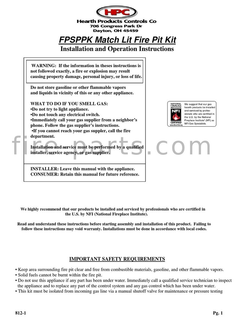
HPC FPSPPK User manual

HPC

HPC FPSPPK User manual

HPC EI Series Installation instructions

HPC

HPC EI Series Installation instructions

HPC MLFPK Series Installation instructions

HPC

HPC MLFPK Series Installation instructions

HPC COPPER FIRE/WATER BOWL Series Installation instructions

HPC

HPC COPPER FIRE/WATER BOWL Series Installation instructions

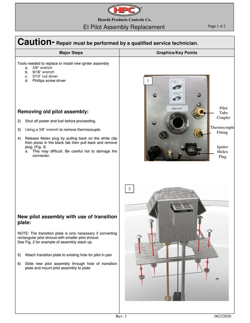
HPC El Pilot Use and care manual

HPC

HPC El Pilot Use and care manual

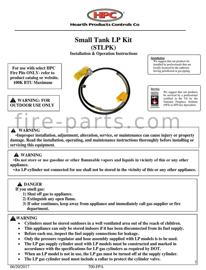
HPC STLPK Installation instructions

HPC

HPC STLPK Installation instructions

Popular Fireplace Accessories manuals by other brands

pleasant hearth Brunet FA092TB quick start guide

pleasant hearth

pleasant hearth Brunet FA092TB quick start guide

Napoleon BT30 manual

Napoleon

Napoleon BT30 manual

kozy heat OCK-S35A manual

kozy heat

kozy heat OCK-S35A manual

Blue Sky Outdoor Living SP2216 owner's manual

Blue Sky Outdoor Living

Blue Sky Outdoor Living SP2216 owner's manual

Dimplex SOP-475-BW install guide

Dimplex

Dimplex SOP-475-BW install guide

Twin-Star International 18DM2105 Assembly instructions

Twin-Star International

Twin-Star International 18DM2105 Assembly instructions

Travis Industries Fireplace Xtrordinair GreenStart Apex 42 instructions

Travis Industries

Travis Industries Fireplace Xtrordinair GreenStart Apex 42 instructions

SBI AC01364 installation instructions

SBI

SBI AC01364 installation instructions

Woodstock Soapstone Palladian 202 manual

Woodstock Soapstone

Woodstock Soapstone Palladian 202 manual

Desa Wall Mantel and Base W26LT Assembly and installation instructions

Desa

Desa Wall Mantel and Base W26LT Assembly and installation instructions

Stoll DV ReFace Installation & operating instructions

Stoll

Stoll DV ReFace Installation & operating instructions

Hearth and Home Technologies Quadra-Fire SANTAFEI-C owner's manual

Hearth and Home Technologies

Hearth and Home Technologies Quadra-Fire SANTAFEI-C owner's manual

Majestic LOGS-KMOD instructions

Majestic

Majestic LOGS-KMOD instructions

Heatilator ST-CFL-24NG Log Placement Instructions

Heatilator

Heatilator ST-CFL-24NG Log Placement Instructions

Empire Comfort Systems DVP1SKR-1 installation instructions

Empire Comfort Systems

Empire Comfort Systems DVP1SKR-1 installation instructions

European Home Scaffold 95 installation guide

European Home

European Home Scaffold 95 installation guide

Napoleon ZEX42CH installation instructions

Napoleon

Napoleon ZEX42CH installation instructions

RealFlame 13054E Assembly instructions

RealFlame

RealFlame 13054E Assembly instructions

manuals.online logo
manuals.online logoBrands
  • About & Mission
  • Contact us
  • Privacy Policy
  • Terms and Conditions

Copyright 2025 Manuals.Online. All Rights Reserved.