manuals.online logo
Brands
  1. Home
  2. •
  3. Brands
  4. •
  5. Woodstock Soapstone
  6. •
  7. Fireplace Accessories
  8. •
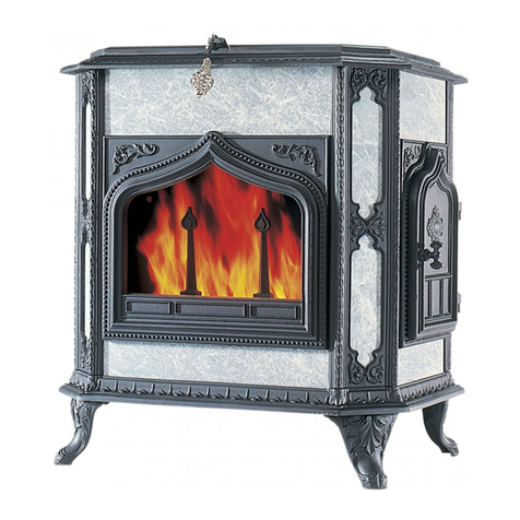
  9. Woodstock Soapstone Palladian 202 User manual

Woodstock Soapstone Palladian 202 User manual

Palladian/ Keystone Models 202/204 Maintenance Kit
Please read all of the instructions before you begin. Confirm that you
have all the necessary tools and parts required. Allow about one hour to
complete the procedure. If you have any questions, technical support is
available toll free at 1-800-866-4344, Monday-Saturday 9:00-5:00 E.T.
Tools Needed:
-½” wrench or socket
-Putty knife
-Wire brush
-Vacuum
-WD-40 or similar penetrating liquid
-Standard size caulk gun
-Sharp scissors
-7/16” wrench and socket
-1/8” allen wrench
-5/32” allen wrench
Materials included in maintenance kit:
-3’ .375 gasket-Loading door (Keystone)
-3’ .312 gasket-Loading door (Palladian)
-3’ .500 gasket-Bypass frame
-3’ .500 gasket-Ash door
-3’ .250 gasket-Under combustor
-11’ adhesive window gasket-surrounding glass
-6’ .250 gasket-Flue collar and cover plate
-1 tube stove cement
-gasket glue
-#00 steel wool
The gasket in your kit has been roughly cut to size and marked with its
diameter and length. To determine its exact length, dry fit the gasket in its
appropriate location and then re-cut. Gasket glue or stove cement will then
be applied to secure each length in its proper place. The steel wool provided
can be used to buff out surface scratches or stains in the soapstone panels.
Use a vacuum to help contain the dust. High temperature touch up paint is
available to match the cast iron frame of your stove, and can be ordered
through Woodstock Soapstone Co.
Please note that the photos displayed here are a mixture of Keystone and
Palladian. The procedures are identical for both models, unless otherwise
specified.
Replacing loading door gasket:
1. Make sure the stove is cool. You will need 3’ of .375 gasket (Keystone)
or .312 gasket (Palladian) and stove cement for the loading door.
2. Open the loading door. Pull straight up on the door. The hinge pins
should slide up and out of the hinges in the door frame. It may be helpful
to swing the door back and forth as you lift.
3. Lay the door face down on a suitable work surface. Use a putty knife to
remove the old gasket. A wire brush may be used to clean out any
cement residue from the gasket channel. Vacuum any leftover debris
from the door and gasket channel.
4. Dry fit the gasket to the door. Start with one end of the gasket at the
center bottom of the door. Press it firmly into the gasket channel all the
way around the door. Do not stretch or compress the gasket as you work
it around the door. Use sharp scissors to cut it to the proper length.
5. Apply a small bead of stove cement (about 3/16”) into the gasket
channel all the way around the door. Again start at the center, bottom of
the door with one end of the gasket and press it into the furnace cement
all the way around the door. Use the putty knife to tuck the gasket in
place if necessary.
6. Return the door to the stove. Align the hinge pins with the hinges on the
door frame. As you press down on the pins it may be helpful to swing
the door back and forth until it is all the way down on the hinges.
7. Close and open the door firmly several times to seat the gasket. If
necessary, adjust the set screw on the door latch for the proper tension.
Use a 7/16” wrench to loosen the lock nut and the 1/8” allen wrench to
turn the set screw.
8. Allow the stove cement to cure for 24 hours before using the stove.
Replacing Bypass frame gasket
1. Make sure the stove is cool. You will need 3’ of .500 gasket and gasket
glue.
2. Remove the cover plate with the allen wrench provided (or go through
the flue collar) to access the catalytic combustor area of the stove.
Remove the heat shield over the combustor using a 7/16” wrench
socket. If you have not already done so remove the shipping bolts that
hold the combustor in place. These bolts do not need to be re-installed.
Remove the combustor from the stove.
3. Use a ½” wrench or socket to remove the bolts that secure the bypass
loop to the top of the bypass door. Spray with penetrating liquid if
necessary. Move the bypass lift guide to the side and open the bypass
door as wide as possible to access the gasket beneath it.
4. With the bypass door fully open, use a putty knife to remove the old
gasket from the bypass frame. Use a wire brush and vacuum to remove
any residual gasket and glue from the gasket channel.
5. Dry fit the replacement gasket by starting one end in any corner of the
gasket channel and working it all the way around the perimeter. Cut to
proper length with sharp scissors. Remove the gasket.
6. Apply a small bead of gasket glue into the gasket channel. Firmly press
the new gasket into the glue. Use a putty knife to seat the gasket into
the channel.
7. Close the bypass door. Attach the bypass lift guide to the bypass door.
It may be necessary to adjust the tension on the bypass door so it has a
seal with the gasket underneath it. Slide a small piece of paper under
the bypass door, close it, and pull the paper out. There should be
resistance and the paper should curl up. To increase pressure on the
bypass door, loosen the top nut on the U-bolt, and then turn the bottom
nut counter clockwise. To decrease pressure on the bypass door turn the
bottom nut clockwise, and do the same to the top nut. Make small
adjustments until the proper seal is reached.
8. Return combustor to the stove and replace the heat shield. You may
also choose to replace the gasket below the combustor before returning
it to the stove.
Replacing combustor gasket
1. Make sure the stove is cool. You will need 3’ of .250 gasket and
gasket glue.
2. Remove the cover plate with the allen wrench provided (or go through
the flue collar) to access the catalytic combustor area of the stove.
Remove the combustor from the stove. Remove the heat shield over
the combustor using a 7/16” wrench or socket. If you have not already
done so remove the shipping bolts that hold the combustor in place.
These bolts do not need to be re-installed.
3. Use a putty knife to remove the old gasket from the area directly
under the combustor. Remove any residual gasket and glue with a
wire brush and vacuum.
4. Dry fit the new gasket. Start one end of the gasket in any corner and
press it into the gasket channel, work it all the way around to the
starting point. Use sharp scissors to cut the proper length. Remove the
gasket.
5. Apply a small bead of gasket glue into the gasket channel. Firmly
press the new gasket into the glue.
6. Return the combustor to the stove. Install the combustor heat shield.
Replacing cover plate/ flue collar gasket
1. Make sure stove is cool. You will need (2) 3’ pieces of .250 gasket
and gasket glue.
2. Use the allen wrench provided to remove the bolts that secure the
cover plate and flue collar to the stove.
3. Place the cover plate and flue collar upside down on a suitable work
surface. Use a putty knife to remove the old gasket and glue from
4. each part. Remove any residual gasket and glue with a wire brush
and vacuum.
5. Dry fit the new gasket. Start one end of the gasket in any corner and
press it into the gasket channel. Do not stretch or compress the gasket
as you work it around the channel. Work it all the way around to the
starting point. Use sharp scissors to cut it to the proper length.
Remove the gasket.
6. Apply a small bead of gasket glue into the gasket channel. Firmly
press the new gasket into the glue.
7. Turn the parts over and allow the glue to set up for 15 minutes before
installing on the stove.
Replacing window gasket
1. Make sure the stove is cool. You will need approximately 11’ of adhesive
window gasket. Spray all hardware to be removed with penetrating
liquid, several applications may be necessary.
2. To remove the combustor scoop and expanded metal from the firebox,
use a ½” socket to remove the single bolt from the support closest to the
loading door. Pull the scoop toward the loading door and forward to
release it. Use caution as the expanded metal is extremely sharp.
3. Use a 1/2” socket or wrench to remove the andirons and glass retainer
from inside the firebox.
4. Remove the two window clips, located halfway up the glass sides, using
a 7/16” socket or wrench.
5. Remove the glass panels from the front frame. Start with the bottom edge
and carefully pull them into the firebox and out through the loading door.
6. Remove the old gasket from the glass panels and clean the glass using
household window cleaner and a soft cloth. (If a more aggressive
cleaning is needed you may use a cleaner made for ceramic cook tops, or
very fine steel wool). Rinse and dry thoroughly.
7. Place a piece of cardboard or some form of protection on top of a
workbench. Apply the gasket to the exterior glass first. The gasket should
be folded evenly around the edge of the glass. Start at one of the shorter
sides and work all the way around the glass panel.
8. On the interior glass start at one of the shorter sides and fold the gasket
evenly around three sides only. Cut the gasket. Measure the gasket for the
remaining long side. Do not fold the last piece of gasket evenly over the
edge of the glass. Apply the adhesive strip to the top edge of the glass
and lay the remainder flat onto the face of the glass. The opposite face
should be free of gasket to accommodate the air wash.
9. Place the panels together. The fully gasketed glass is the exterior panel.
The non gasketed face of the interior panel is the firebox side.
10.Slide the two panels up into the window frame together ensuring that
they are aligned with each other.
11. Fasten the panels in position with the two window clips using a 7/16”
socket or wrench. Make sure you angle the clips so that they are hidden
from view before tightening completely.
12. Install the glass retainer and andirons.
13. Confirm there is a 1/4” space between the interior glass panel and the air
guide. (A ¼” drill bit is helpful to check the gap). The air guide is at the
top front of the firebox. Loosen the two bolts with a 7/16” socket if
adjustment is necessary.
14. Replace the combustor scoop and expanded metal.
NOTE: There is no “cure time” to abide by, however the adhesive on the
window gasket may emit a strong odor for the first 4-8 hours of high
temperature use.
Replacing ash door gasket
1. Make sure the stove is cool. You will need 3’ of .500 gasket and stove
cement.
2. Remove the ash door from the base of the stove for easier access to the
gasket. Use a ½” socket to remove the nut and lock washer from the
bolt that acts as the door hinge. Slide the bolt out of the stove base.
3. Use a putty knife to remove the old gasket. A wire brush may be used
to clean out any cement residue from the gasket channel. Vacuum any
leftover debris from the door and gasket channel.
4. Dry fit the gasket to the door. Start with one end of the gasket at the
center of the hinge side of the door. Press it firmly into the gasket
channel all the way around the door. Do not stretch or compress the
gasket as you work it around the door. Use sharp scissors to cut it to
the proper length.
5. Apply a small bead of stove cement (about 3/16”) into the gasket
channel all the way around the door. Again start at the center of the
hinge side of the door with one end of the gasket and press it into the
furnace cement all the way around the door. Use the putty knife to tuck
the gasket in place if necessary.
6. Install ash door onto stove base. Keep the door closed to seat the
gasket.
Sealing the firebox seams
1. Make sure the fire is completely extinguished and no hot coals or
embers are hidden in the ashes in the firebox.
2. Remove all ash from the firebox. Use a vacuum to thoroughly clean the
firebox.
3. Use a putty knife to remove any loose stove cement from the corners
and base of the firebox. Vacuum out any debris.
4. Apply a bead of fresh stove cement over the existing cement in the
corners, around the base, and around the cast iron door and front
frames.
5. Smooth the new stove cement with your finger or putty knife. Clean
hands and tools with warm soapy water.
6. Allow 48 hours for the stove cement to cure. 1 or 2 small fires will drive
any residual moisture from the cement and finish the curing process.
We need your help! Woodstock Soapstone Co. takes great pride in
providing the highest quality products as well as the best customer service in
our industry. We welcome your suggestions and input to help us achieve
these goals. If you have any comments to improve our products, service, and
information provided in these instructions please contact us at (800) 866-
4344 or [email protected]. Thank you.
6/11/10

This manual suits for next models

1

Other Woodstock Soapstone Fireplace Accessories manuals

Woodstock Soapstone Fireview 201 User manual

Woodstock Soapstone

Woodstock Soapstone Fireview 201 User manual

Woodstock Soapstone W-232 Operating and safety instructions

Woodstock Soapstone

Woodstock Soapstone W-232 Operating and safety instructions

Popular Fireplace Accessories manuals by other brands

Napoleon Wolf Steel Silhouette installation manual

Napoleon

Napoleon Wolf Steel Silhouette installation manual

Valor Horizon 614CVI installation manual

Valor

Valor Horizon 614CVI installation manual

IHP DRFTWD-LOG60 installation instructions

IHP

IHP DRFTWD-LOG60 installation instructions

Lennox Eyebrow Lintel Kit ELDV-35 installation instructions

Lennox

Lennox Eyebrow Lintel Kit ELDV-35 installation instructions

Napoleon CFF installation instructions

Napoleon

Napoleon CFF installation instructions

Valor G3.5 Series installation manual

Valor

Valor G3.5 Series installation manual

EdilKamin SERBATOIO 250 Installation, use and maintenance

EdilKamin

EdilKamin SERBATOIO 250 Installation, use and maintenance

Empire Comfort Systems LS50TINF installation instructions

Empire Comfort Systems

Empire Comfort Systems LS50TINF installation instructions

Valor Legend G3 738 NGK installation instructions

Valor

Valor Legend G3 738 NGK installation instructions

European Home Scaffold 42 installation guide

European Home

European Home Scaffold 42 installation guide

Valor LT1 2500K quick start guide

Valor

Valor LT1 2500K quick start guide

livin flame SAFIEN Installation instructions & operating manual

livin flame

livin flame SAFIEN Installation instructions & operating manual

kozy heat NCK-C39-D quick start guide

kozy heat

kozy heat NCK-C39-D quick start guide

Empire Comfort Systems DFF30RBL installation instructions

Empire Comfort Systems

Empire Comfort Systems DFF30RBL installation instructions

Gason Eureka Jindara Duet installation instructions

Gason

Gason Eureka Jindara Duet installation instructions

Travis Industries DVL EmberGlo GSR2 Insert owner's manual

Travis Industries

Travis Industries DVL EmberGlo GSR2 Insert owner's manual

Selkirk SUPERVENT 2100 INSTALLATION INSTRUCTIONS & MAINTENANCE GUIDE

Selkirk

Selkirk SUPERVENT 2100 INSTALLATION INSTRUCTIONS & MAINTENANCE GUIDE

Gardus SootEater operating instructions

Gardus

Gardus SootEater operating instructions

manuals.online logo
manuals.online logoBrands
  • About & Mission
  • Contact us
  • Privacy Policy
  • Terms and Conditions

Copyright 2025 Manuals.Online. All Rights Reserved.