HRW HPD0460BN User manual

HRW Limited Unit E, 11/F, Sun Ying Industrial Centre Ph +852 2546 7402
9 Tin Wan Close, Tin Wan Fax +852 2546 7403
Hong Kong www.hrw.hk
HPD0460BN Multi-Function Room Units, BACnet MS/TP
FW4.02
The HPD0460BN devices may be used as BACnet networked HVAC devices or standalone; as an HMI
for control and display of multiple controllers on a local network, as a controller with high flexibility for
user configuration to suit a wide variety of control applications or as a network manager including multi-
zone annual time scheduling. The display is programmable to indicate user specific text and dynamic
data points. Data points may be adjusted directly at the LCD (parameters such as set-points, fan-
speeds and manual overrides). The text and dynamic values for each of the 32 user lines may be set as
small font size or large font size.
The user push-buttons, indication LED’s and an audible sounder may be independently programmed to
suit the user application. Physical I/O points may be used in the system independently or, subject to the
version, by the internal control loops and logic blocks.
Depending on the version, logic function blocks enable easy configuration of a variety of functions
including Economy Changeover (temperature or enthalpy), VAV Volume, Occupancy, Hours Run
monitoring, Minutes Run monitoring, Lead/Lag changeover, instantaneous Power calculation (kW, BTU)
and a wide array of hysteresis & dead-band/live-band choices (Compare function).
The time clock version features a 365 day clock/calendar with four channel time-switch, 20 holidays
(one-off or annually recurring) and summer/winter time.
Common Features
32 line user programmable dot matrix LCD display with pop-up alarm text feature
1 Room temperature sensor on-board
1 Input programmable as DI or 10k NTC
2 Universal inputs (DI, 10k NTC, 100k NTC, 0-10Vdc or 4…20mA)
6 Digital outputs (ON/OFF, single or multi stage, 3-point floating, PWM)
4 User programmable operator buttons
4 User programmable indication LED’s
1 User programmable audible alert beeper
48 Network Interface Objects (NIO’s) for Peer-to-Peer communication
8 Virtual Digital Inputs (VDI)
8 Virtual Universal Inputs (VUI)
Typical Applications
Temperature, humidity, pressure, IAQ, universal
On/off, 3-point modulating, PWM (Pulse Width Modulation), step control, DX
Residential, Commercial, Hotels
Local User Interface, network interface, networked or standalone controller
Time-clock & calendar / time-switch, networked or standalone
Versions
HPD0460BN Network HMI, 10 Point, 24Vac
HPD0460BNC Network HMI / Universal Controller, 10 Point, 24Vac
HPD0460BNCT Network HMI / Universal Ctrl / Scheduler, 10 Point, 24Vac
HPD0460BNT Network HMI / Scheduler, 10 Point, 24Vac

HRW HPD0460BN V402 Manual 150622.docx E. & O. E. / Subject to change without notice Page 2 of 33
Feature Summary
6 Digital Outputs (DO) with power up presetting
1 NTC 10k temperature sensor internal (UI1)
1 Universal input (UI) fixed NTC 10k or DI n/o or n/c (UI2)
2 Universal Inputs (UI - user configurable analogue [AI] or binary [DI, n/o or n/c])
8 Virtual Digital Inputs (VDI)
8 Virtual UI’s (VUI)
8 Digital Logic blocks (DL) ©
8 Analogue Logic blocks (AL) ©
8 PI Control Loop blocks (CL) ©
48 Network Interface Objects (NIO) for peer-to-peer connectivity
32 user programmable LCD lines (text and dynamic point per line)
UI’s user scalable and units user settable (C, F, rH, %, Pa, kPa, PPM, etc.)
Connected sensors may be calibrated and filtered by way of the UI configuration
DO change-of-state delay timer (short cycle timer)
365 day time clock & calendar
20 holidays, recurring or one-off event
Summertime/Wintertime
4 Channel time switch
4 Push buttons, programmable to suit application (DI1, DI2, DI3, DI4)
4 Navigation buttons, up/down/right/left (DI5, DI6, DI7, DI8)
4 LED’s, indication programmable to suit application (DO7, DO8, AO1, AO2)
Audible alarm programmable to suit application (AO3)
LCD Backlight, 60 sec after any button press
Isolated, 256 node (1/8th load), RS485 network driver
Communication speeds from 2400 baud up to 76800 baud
System-wide unique device addressing
BACnet application services; Single-Read, Multiple-Read, Single-Write, Who Is, I Am, Who
Has, I Have
BACnet priority array
Automatic communication resumption after a power loss
PC configuration by text file download using FUNCPROG or by direct parameter settings entry
Upload text file data for retrieving lost application settings, for re-use in other controllers
© = Available in Controller versions = Available in Time Clock versions

HRW HPD0460BN V402 Manual 150622.docx E. & O. E. / Subject to change without notice Page 3 of 33
OPERATION OVERVIEW ....................................................................................................................................4
BACNET OBJECT INSTANCES ..........................................................................................................................5
BACNET PRIORITY ARRAY ...............................................................................................................................5
USER INTERFACE .................................................................................................................................................6
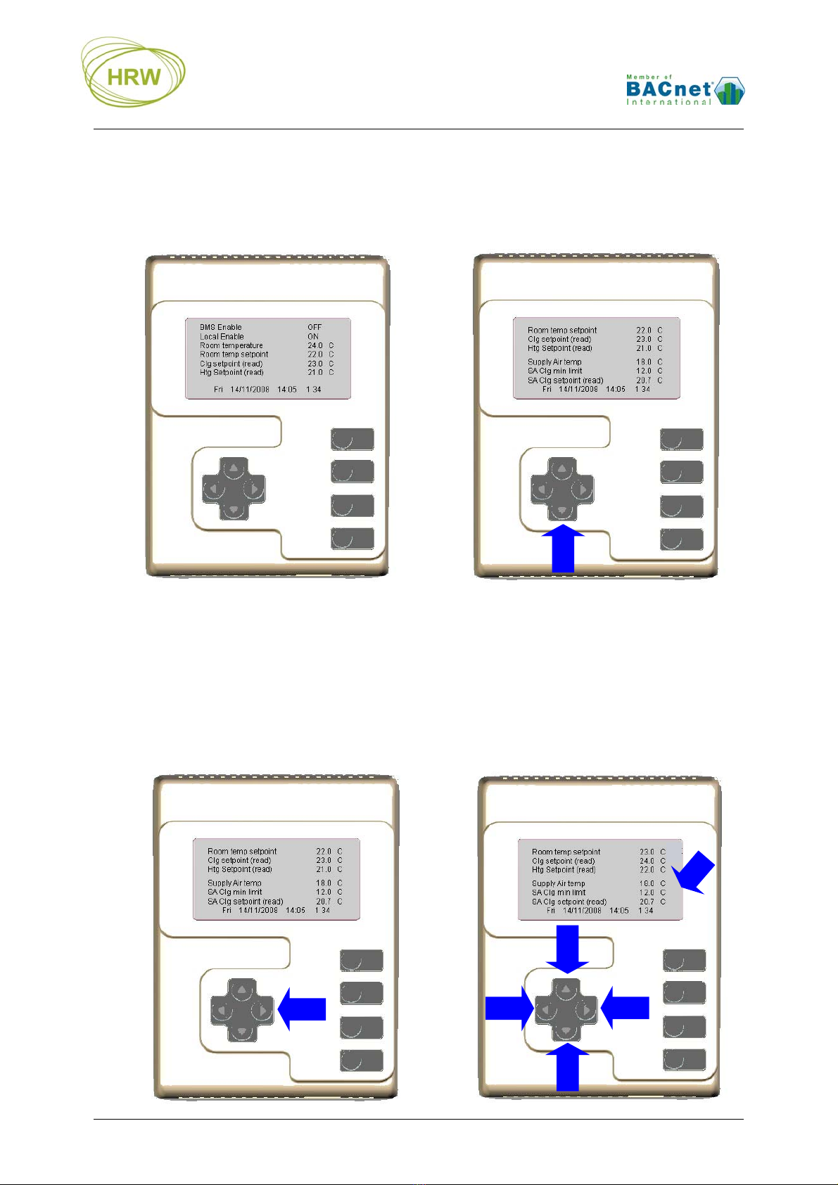
INTERFACE OPERATION ..........................................................................................................................................7
LARGE FONT DISPLAY ...........................................................................................................................................8
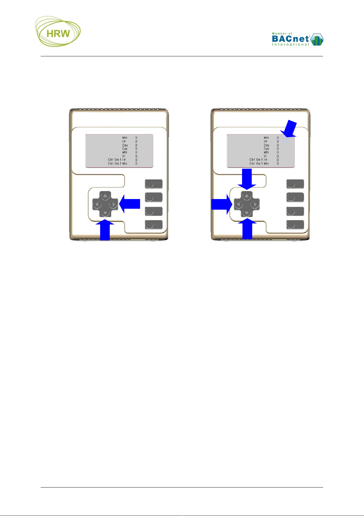
CLOCK & TIME-SWITCH SETTING ...........................................................................................................................8
FUNCTION BLOCK OBJECTS & SUB-PARAMETERS ................................................................................ 10
TERMINAL MODE .............................................................................................................................................. 13
HYPERTERMINAL SETTINGS ................................................................................................................................. 13
Additional Settings..........................................................................................................................................14
Connecting at 76800 Baud Rate.....................................................................................................................14
Saving HyperTerminal Settings......................................................................................................................14
Changing Baud Rate.......................................................................................................................................14
BREAK IN TO TERMINAL MODE ............................................................................................................................ 15
ADMINISTRATION COMMANDS ............................................................................................................................. 1 6
DISPLAY NAVIGATION ......................................................................................................................................... 17
SUMMARY SCREEN & LCD SETTING ................................................................................................................... 17
MANUAL OVERRIDE / RELEASE............................................................................................................................ 18
OPERATIONAL DISPLAYS ............................................................................................................................... 19
USER SUMMARY SCREEN ..................................................................................................................................... 19
DOWNLOAD TEXT FILE ........................................................................................................................................ 20
‘MAIN’ PHYSICAL I/O DISPLAY ........................................................................................................................... 21
POINT LIST DISPLAY ............................................................................................................................................ 21
CONTROL LOOP (CL) DISPLAY ............................................................................................................................ 22
DIGITAL LOGIC (DL) & ANALOGUE LOGIC (AL) DISPLAY .................................................................................. 23
NETWORK INTERFACE OBJECT (NIO) DISPLAY.................................................................................................... 24
RESET TO FACTORY DEFAULT ..................................................................................................................... 25
UPLOAD TEXT FILE ........................................................................................................................................... 25
UNIVERSAL INPUTS ........................................................................................................................................... 26
LINEARISATION TABLE ................................................................................................................................... 27
FACTORY DEFAULT SENSOR TYPES ..................................................................................................................... 27
ACTIVE SENSOR SCALINGS .................................................................................................................................. 27
PASSIVE SENSOR DEFINITION ............................................................................................................................... 28
RESET TO FACTORY DEFAULT .............................................................................................................................. 28
INSTALLATION & COMMISSIONING ........................................................................................................... 29
CONNECTIONS .................................................................................................................................................... 30
DIMENSIONS ........................................................................................................................................................ 30
TECHNICAL DATA ............................................................................................................................................. 31
ORDERING INFORMATION ............................................................................................................................. 32
ACCESSORIES ....................................................................................................................................................... 32
OTHER HP_BN SERIES DEVICES .......................................................................................................................... 32
DOCUMENT UPDATE HISTORY ..................................................................................................................... 33

HRW HPD0460BN V402 Manual 150622.docx E. & O. E. / Subject to change without notice Page 4 of 33
Operation Overview
All physical inputs, outputs and internal logic & control function blocks, and critical control loop
parameters are numerically represented as an ‘Object’. The object is a function block’s output value.
Depending on the purpose of a function block the object may have a range of sub-parameters available
for defining the block’s function and the operational features & limitations of the function. In the case of
control loops the active set point, the proportional band and the integral time sub-parameters are also
represented as objects for network access and remote tuning of a control loop if required.
In this document the term ‘Objects’ will mainly be used in the context of BACnet networks but will
otherwise be referred to as a ‘point’ or ‘points’ when discussing specific control applications.
The process of setting up function blocks and connecting function blocks to form an application uses
simple text lines therefore it is not necessary to learn a complex programming language. The settings
may be manually typed in to the device or, using the FUNCPROG 141101 programming tool which
provides a visual representation of each block, an application text file may be created, saved and
downloaded to the device as a complete group of settings. Earlier versions of FuncProg may be used
but the latest feature settings will not be directly available in those earlier versions.
The ability to make single setting changes directly at the device makes for easy debugging and
commissioning.
The function blocks comprise:
Physical I/O for connection of input switches, sensors and output control devices
Virtual inputs for taking over external commands and values from other network devices or for
manual settings and overrides
Logic blocks for event based reactions and influences ©
PI Control Loop blocks for set point based control reactions ©
Time Switch channels
Network settings
In all cases points may be manually overridden for testing & commissioning purposes or for service
override. In respect of BACnet priority arrays manual overrides are Priority 9 (factory default = Null /
internal program control = 16).
Connection to the device for programming and service is via a terminal program such as HyperTerminal
(recommended). While on-line to the device it is possible to view point statuses and where applicable,
any dependent or influencing point’s connections. Statuses are updated live to the terminal screen
every 10 seconds or manually refreshed any time by pressing the enter key.
In additional to the predefined point displays a user-defined display is available for a customised point
summary related to an application. The user display may contain up to 32 lines of user text with or
without dynamic points included.
In the base HPD0460BN version which is without PI controller or time clock functions, the physical
inputs may be read from other controllers on the network and the outputs may be driven by other
controllers on the network. This means the HPD0460BN may be used as a user interface to a single
controller or as a user interface to multiple controllers on the network.
The HPD0460BNC, T and CT versions feature control and/or logic and/or time-switching capabilities
which enable them to work as controllers in their own right, either locally or providing control to remote
controllers and I/O expansion devices. In all versions the user has the freedom to specify own display
text in up to 32 lines with or without dynamic object displays. Text lines may be programmed to be
invisible until a specific object (or group of objects) met a predefined criteria at which time the text will
‘pop-up’ at the top of the display. When the predefined criteria is no longer true then the text will no

HRW HPD0460BN V402 Manual 150622.docx E. & O. E. / Subject to change without notice Page 5 of 33
longer be displayed. This feature is designed for use as alarm indication and can be used together with
the programmable LED’s and audible beeper to raise attention to an alarm situation.
BACnet Object Instances
Up to 110 function blocks exist in the device depending on the version. Because many objects may be
Binary or Analogue, and may be seen as an Input, an Output or a Value, the final total of discoverable
and device relevant object instances may be up to 124.
A physical universal input (UI) may be an AI (Analogue Input) or AV (Analogue Value) but
when used as a digital input then it’s object instance would be a BV (Binary Value)
A Virtual Universal Input (VUI) is seen as an AV (Analogue Value)
A physical digital output is a BO (Binary Output) by default but if programmed for PWM control,
which has a control value of 0…100%, then it is seen as an AV (Analogue Value)
Using UI3 as an example:
Description: Physical universal input
Object #: 19
Object Instance when binary DI: BV19
Object Instance when analogue sensor: AI19 or AV19
Using AL1 as an example:
Description: Analogue Logic block
Object #: 53
Object Instance when Digital function: BV53
Object Instance when Analogue function: AV53
The common reference in all cases is the object # therefore during device Object Discovery over the
network the option of Input, Output or Value is decided based on the programmed application use of the
object in question.
BACnet Priority Array
The BACnet protocol utilises a Priority Array for each object to enable various network devices to take
control of a device’s object based on the level of need. Priority 16 is the least significant level and may
be considered normal ‘Auto’ operating level. Priority 1 is the highest control level, generally used for
emergency control under fire condition or similar events.
In respect of this device:
The objects are null priority by default
Commands from the internal control program of the device are at priority level 16
Manual commands via terminal mode operate at priority level 9
Release of a manual results in an object reverting to next lowest and still valid priority level
Commands from the network to DO, AO, VUI and VDI objects are remembered after a power
reset if priority 1…8
Commands from the network to Proportion Band & Integral Time points of Control Loops are
written to those objects if other than null priority

HRW HPD0460BN V402 Manual 150622.docx E. & O. E. / Subject to change without notice Page 6 of 33
User Interface
The illustration below shows a factory default HPD0460BNCT (full controller & time-clock functionality)
Using HyperTerminal the display may be customised either by manual configuration or download of an
application text-file.
Up to 32 display lines
Small or large font
Up to 21 text characters per line (small font)
Each display line may include a dynamic point
The dynamic point’s unit tag may be customised
The time switch display above indicates ‘1 34’ which tells us that switch channels 1, 3 & 4 are ON
1 – Button 1 / LED 1
2 – Button 2 / LED 2 All LED’s invisible
unless active
3 – Button 3 / LED 3
4 – Button 4 / LED 4
5 – LCD scroll UP / adjust value UP
6 – LCD scroll DOWN / adjust value DOWN
(hold continuous to access clock setting)
7 – LCD select value for adjustment / Write value
8 – LCD release manualled value to AUTO
9 – LCD user display
10 – Calendar/Clock/Time Switch channels status

HRW HPD0460BN V402 Manual 150622.docx E. & O. E. / Subject to change without notice Page 7 of 33
Interface Operation
After download of an application text-file
the HPD0460 screen may appear as in
the following example:
Press the down navigation button (D) to
scroll down to see up to 32 lines of user
display:
D
Press the up or down button to scroll through display lines. A press of the right button (R) makes cursor aligned point
available for adjustment (A) via the up and down buttons (U/D). To save the change press and hold the right button (R)
until a beep is heard. To exit adjustment mode without saving the change press the left button (L).
Exiting a set point adjustment without saving the change will result in the start up default being retained after a power
reset. If an output is being manualled via the LCD and the change is to be a start-up default then after making the
adjustment press and hold the right button until the a beep is heard. To release a M (Manualled) point back to auto
align the cursor with the point and press the left button.
Right side cursor
indicates point
now Adjustable
using the up/down
buttons
D
U
L
R
R
› › ‹
A

HRW HPD0460BN V402 Manual 150622.docx E. & O. E. / Subject to change without notice Page 8 of 33
Large Font Display
Any of the 32 display lines may be programmed for large font. Below are two example display
possibilities using both standard and large fonts
Clock & Time-switch Setting
In versions with 365 day time-clock & four-channel time-switch.
Each time switch channel has two On times and two Off times available per day
Twenty holidays, either recurring annually or one-off events, may be programmed
Each time switch channel may be applied to any days of the week combination, and/or
exception day 8 which is active on holidays
Wintertime/Summertime shift may be set to occur automatically
European or North American date format may be set
› ‹

HRW HPD0460BN V402 Manual 150622.docx E. & O. E. / Subject to change without notice Page 9 of 33
A long press of the left button (L) after making all settings will exit back to the normal display. Saving of
the new clock settings will be confirmed by a beep being heard.
Notes:
Hours may be set in the range 0…23
Minutes may be set in the range 0…59
Holiday date setting with year =0 will occur every year
Holiday date setting with year >0 will occur once only, in the set year
To enter the clock setting mode press and
hold the down button (D) until the display
shown below is visible (15sec). Scroll so that
the line cursor is aligned with the desired
setting line then press the right button (R) to
select the value for adjustment
Press the up or down buttons (U/D) to adjust
the setting. Press the left button (L) to save the
exit adjustment of the current clock parameter.
Cursor indicates point now
Adjustable using the up/down
button
s
U
D
L
R
D
› › ‹
A

HRW HPD0460BN V402 Manual 150622.docx E. & O. E. / Subject to change without notice Page 10 of 33
Function Block Objects & Sub-Parameters
The following is an overview of the function block features and options. For in-depth description of
function choices and their use please also download or request the separate FUNCPROG Application
Tool document.
Function Block Object Para # Description Selection Options
Digital Input 1…4 1…4
x00=
x01=
x02=
Buttons 1…4, input type
Output OR
Output AND
7 - Digital, 14 - n/c, 15 - Toggle on/off
Object #
Object #
Digital Input 5…8 5…8 x00=7 Navigation buttons Fixed, dedicated to Up, Down, Right, Left
respectively
Digital Output 1…6
Parameters 00…05:
©
Parameters 06…09:
Available on all versions
9…14
(x)x00=
(x)x01=
(x)x02=
(x)x03=
(x)x04=
(x)x05=
(x)x06=
(x)x07=
(x)x08=
(x)x09=
OR1
OR2
AND
PWM cycle time (sec)
ON
OFF
Minimum ON time (sec)
Minimum OFF time (sec)
Maximum Run time (sec)
Remember last state at power return
Object #
Object #
Object #
0…255
% of control loop demand
0…255
0…255
0…1000
0 - Disable, 1 Enable
LED 1 & 2
(Digital Output 7…8) 15…16
(x)x00=
(x)x01=
(x)x02=
(x)x03=
(x)x04=
(x)x05=
(x)x06=
(x)x07=
(x)x08=
(x)x09=
OR1
OR2
AND
PWM cycle time (sec)
ON
OFF
Minimum ON time (sec)
Minimum OFF time (sec)
Maximum Run time (sec)
Remember last state at power return
Object #
Object #
Object #
0…255
% of control loop demand
0…255
0…255
0…1000
0 - Disable, 1 Enable
Universal Input 1 17 1700=5 Fixed NTC 10k internal 5 - 10k NTC (-10…90°C) [Ctx]
Universal Input 2 18 1800= Sensor type
5 - 10k NTC (-10…90°C) [Ctx]
7 - DI [D]
14 – DI n/c [DNC]
15 - Toggle on/off [D T]
Universal Input 3…4 19…20 xx00= Sensor type
0 - 100k NTC (-10…90°C) [Ctc]
2 - 0-10Vdc (0…100%) [%V1]
3 - 4…20mA (0…100%) [%mA]
5 - 10k NTC (-10…90°C) [Ctx]
7 - DI [D]
8 - % (0-100%) [%]
9 - Seconds [Sec]
14 - Digital normally-closed [DNC]
15 - Toggle on/off [D T]
Common settings of UI 1…4
xx01=
Input calibration - Offsets the
measured value up to 10% of the
sensor range
Any value within 10% of the sensor range
xx02=
Filter incoming sensor measurement
when the connected sensor is
unstable
0 - Minimum (factory default)
1…9 - User setting where 9 represents
the maximum filtering sample time
For unstable sensors then a setting of 1
or 2 will typically be enough filtering to
result in a stable measurement
xx03=
xx04=
Output OR*
Output AND*
Object #
Object #
* Digital 1 = 1000 (100%) when applied to these analogue logic functions. Analogue values will act as a
Output Minimum when applied to an Output OR and Output Maximum when applied to an Output AND.

HRW HPD0460BN V402 Manual 150622.docx E. & O. E. / Subject to change without notice Page 11 of 33
Function Block Object Para # Description Selection Options
LED 3 & 4
(Analogue Output 1…2)
Parameters 00…04:
©
25…26
xx00=
xx01=
xx02=
xx03=
xx04=
OR1
OR2
AND
100%
0%
Object #
Object #
Object #
% of control loop demand
Audible alarm beeper
(Analogue Output 3)
Parameters 00…04:
©
27
xx00=
xx01=
xx02=
xx03=
xx04=
OR1
OR2
AND
100%
0%
Object #
Object #
Object #
% of control loop demand
Virtual Digital Input 1…8 29…36 x01=
x02=
Output OR
Output AND
Object #
Object #
Digital Logic 1…8
© 37…44
xx00=
xx01=
xx02=
xx03=
xx04=
xx05=
xx06=
xx07=
xx08=
xx09=
Function
Input1
Input2
Input3
Input4
Delay On
Delay Off
Output OR*
Output AND*
Occupancy
OR, NOR, AND, NAND, XOR, NXOR,
Lead/Lag, Occupancy
Object #
Object #
Object #
Object #
0…44 or 53…65,535 sec,
or Point # 45…52 for remote settable
Object #
Object #
Object #
Virtual Univ. Input 1…8 45…52
xx00=
xx01=
xx02=
Set sensor type
Output OR*
Output AND*
Same as UI selection Type 0… 9, 10 -
Hours Run, 11 – Minutes Run
Object #
Object #
Analogue Logic 1…8
© 53…60
xx00=
xx01=
xx02=
xx03=
xx04=
xx05=
xx06=
xx07=
xx08=
xx09=
xx10=
xx11=
xx12=
Function
Set output-relevant sensor type
Input1
Input2
Input3
Input4
Offset
Value In 1
Value Out 1
Value In 2
Value Out 2
Output OR *
Output AND *
Max, Min, Avg, Signal-Select, +, -, *, /, or
Eco-Changeover, Proportion, VAV
Volume, Up/Down counter, Power,
Compare
Same as UI selection
Object #
Object #
Object #
Object #
Relative value
Shift input start value
Shifted output minimum value
Shift input stop value
Shifted output maximum value
Object #
Object #
Control Loops 1…8
©
61…68 Read
only Setpoint Absolute value
69…76
xx00=
xx01=
xx02=
xx03=
xx04=
xx05=
xx06=
xx07=
xx08=
xx09=
xx10=
Start/Stop (Dig/Analogue)
Input (Analogue)
Occupied Setpoint
Unoccupied Setpoint
Protection Setpoint
SetPoint Deadband
Setpoint Max.
Setpoint Min.
Output action
Output OR *
Output AND *
Object #
Object #
Absolute value
Absolute value
Absolute value
Relative value
Absolute value
Absolute value
0 – Direct, 1 – Reverse, 2 – Direct 50,
3 – Reverse 50
Object #
Object #
77…84 xx= Proportional Band Absolute value based on related sensor
range
85…92 xx= Integral time 0…1000 Seconds
Clock Channels 1…4
101…104 xxx00=
xxx01=
Output OR
Output AND
Object #
Object #
* Digital 1 = 1000 (100%) when applied to these analogue logic functions. Analogue values will act as a
Output Minimum when applied to an Output OR and Output Maximum when applied to an Output AND.

HRW HPD0460BN V402 Manual 150622.docx E. & O. E. / Subject to change without notice Page 12 of 33
Function Block Object Para # Description Selection Options
Network Interface
Objects (NIO) 105…112
xxx00=
xxx01=
xxx02=
xxx03=
xxx04=
xxx05=
xxx06=
xxx07=
Target node number
Object Instance type
Target Object Instance within target
node
Sensor type
Read/Write
Read-Value Scaling
Output OR *
Output AND *
Device # in the same network
0 - Disabled
1 - DI
2 - DV
3 - DO
4 - AI
5 - AV
6 - AO
1…65,535
Same as UI selection
0 = Read status of target Instance of
target node
1…112 = Write local Instance status to
target Instance of target node
0 – Normal (apply Sensor Type units
only), 1 - Raw (apply Sensor Type units,
intercept & scaling)
Object #
Object #
* Digital 1 = 1000 (100%) when applied to these analogue logic functions. Analogue values will act as a
Output Minimum when applied to an Output OR and Output Maximum when applied to an Output AND.
LED 3 & 4 and the audible beeper have a fixed 5sec PWM cycle time with 1sec resolution. Therefore
if digital 1 or 100% is applied then the LED/beeper will be on continuously. If 60% applied then the
LED/beeper will be on for 3sec, off 2sec, on 3sec, and so on. The minimum applied value for an output
reaction is 20% (1sec on, 4sec off). In HPD0460BN these outputs may be driven by peer-to-peer
controllers on the network or via the internal NIO’s reading in object values from other controllers on the
network. HPD0460BNC, T or CT can control objects 25…27 directly using their own internal function
blocks.

HRW HPD0460BN V402 Manual 150622.docx E. & O. E. / Subject to change without notice Page 13 of 33
Terminal Mode
The HPECOMU data cable with USB connection is used for terminal mode between the device and a
PC running a terminal program. HyperTerminal is recommended. The driver for the HPECOMU cable
may be downloaded from www.hrw.hk, Resources / Tools, section.
HyperTerminal Settings
For successful communication between HyperTerminal and the device, initial Properties setup of
HyperTerminal should be as per the screen prints below.
‘Connect to’ Comm Configuration: ‘Settings’ General:
‘Settings’ ASCII Setup:
9600

HRW HPD0460BN V402 Manual 150622.docx E. & O. E. / Subject to change without notice Page 14 of 33
Additional Settings
Some PC platforms may need keyboard response adjustment for initial Terminal Mode success. These
settings may be done via the PC Control Panel >> Keyboard Settings:
Fastest Repeat rate
Shortest Delay time
Fastest Cursor Blink rate
Connecting at 76800 Baud Rate
Because HyperTerminal does not support 76800 baud then after setting to 76800 the device baud rate
will remain at 9600 baud for HyperTerminal communication and switch to 76800 after Writing the new
baud rate and eXiting terminal mode.
To allow later terminal communication a device set with 76800 baud will operate at 9600 baud for the
first 5 seconds after a power-up. If no attempt to connect the terminal at 9600 baud is made within 5
seconds of a power-up then the device will automatically switch to 76800 for normal network operation.
Saving HyperTerminal Settings
For ease of connection it is recommended to save the HyperTerminal setup for each baud rate you may
wish to use with an easily recognised configuration name. For example:
HPECOM 24 (2400)
HPECOM 48 (4800)
HPECOM 96 (9600)
HPECOM 19.2 (19200)
HPECOM 38.4 (38400)
HPECOM 57.6 (57600)
Changing Baud Rate
After changing to a new baud rate the controller will not start running at the new baud rate until the
change has been Written (W). If setting a new baud rate via text file application download the new baud
rate will be applied immediately the download is completed (auto-Write).
In either case, after the Write action, you will need to reconnect the terminal program at the new baud
rate if you wish to continue the terminal session.

HRW HPD0460BN V402 Manual 150622.docx E. & O. E. / Subject to change without notice Page 15 of 33
Break in to Terminal Mode
When HyperTerminal is running and the HPECOM cable is connected to the device the initial terminal
screen will be receiving an ASCII character dump which is the BACnet transmission from the device.
The ASCII dump will appear differently with different device address setting and if HyperTerminal baud
rate is different to the baud rate set in the device. Below is an illustration of how the ASCII dump will
look for a device at default settings; address 98 and 9600 baud.
To break in to terminal mode set Caps Lock on and hold the ‘T’ character key continuously
(TTTTTTT…). After five (5) T’s have been sent to the device it will switch to terminal mode. At this point
the BACnet activity on the network will be halted and the device will display the default user screen.

HRW HPD0460BN V402 Manual 150622.docx E. & O. E. / Subject to change without notice Page 16 of 33
Administration Commands
Function Enter Result Options / Comments
Start
communication TTTTT(TTT…) Display of configuration
and I/O status
With the Caps Lock on, hold the T key down
until the screen updates with HPE data. It is
not necessary to press the enter key to start
communication.
Download text
file DE Make ready for file path Menu: Transfer > Send textfile > file
Upload text file UE
All settings are uploaded to
the terminal for archive or
re-use
HyperTerminal: Start a Capture Text
procedure before invoking UE then stop the
Capture after Upload complete.
Indigo you may simply copy the text on the
terminal screen to a text file.
Reset to
Factory Default FD=1 Reset to ex-factory settings FD will be displayed in the top line of the I/O
summary screen after reset
Set node
address (MAC)
98=1…98,
100…127,
128…247
Network node number is
assigned
Example: 98=25
1…98 / 100…127 the device will be a ‘token
passing master’
128… 247 the device will become a network
slave after power reset
Set system
Device Instance DI=0…4194303 Unique Device Instance is
assigned
Example: DI=401025 (building 4, network 1,
node 25)
Set baud rate 99=… Network comms speed is
set
2400, 4800, 9600, 19200, 38400, 57600,
76800 Example: 99=9600
After Writing new comm. speed it will be
necessary to reconnect with Terminal at the
new comm. speed to continue the terminal
session!
Set Maximum
Master address MM=1…127
Highest Master device
address on the network is
registered
Next address searching limited to MM
address
Set Sys.
Vendor ID
(SysVid)
SV=0…255 System vendor specific
features may be available
SV=0 applies generic BACnet operation. If
an entered ID is not implemented then the
generic operation will be applied
Zero the Reset
counters
95=0, 96=0,
97=0
Each Reset counter is
zeroed
Factory diagnostics
Resets = <95> <96> <97>
Rx timeout, Tx timeout, Hardware reset
Write values as
default W Changes written. Always do this after making changes that
you wish to be permanent
Exit
communication X
Communication with
HyperTerminal no longer
active
Auto X after 240sec without key entry. After
eXit unplug the HPECOM cable to allow
network communication to take place

HRW HPD0460BN V402 Manual 150622.docx E. & O. E. / Subject to change without notice Page 17 of 33
Display Navigation
Function Enter Result Options / Comments
Display Control
Commands
A1…8 Display Analogue Logic block A1, A2, … A8
C1…8 Display Control Loop block C1, C2, … C8
D1…8 Display Digital Logic block D1, D2, … D8
M Display I/O summary screen M
N Display Network Interface Object
(NIO) bindings N
P Display Point status list
Enter P or P1 to display the first 21 Objects. Enter
Pxx (where ‘xx’ is a point #) to display any other
point and the following 20 points
S Return to User Summary display S
SS Screen Static Disable 10 sec live update
SL Screen Live Enable 10 sec live update
SLLD Screen Line Logic Display Enable/Disable display of object numbers and
screen line numbers in the summary display
Summary Screen & LCD Setting
Function Line Method Result Options / Comments
Summary Display
Lines & dynamic point
setting
SL1…32 SL(x)x=abc… Assign Screen Line text as information or in
relation to SP1…24
Alpha/numeric, 40
characters max.
SP1…32 SP(x)x=nnn Assign Screen Point dynamic point value Object #
SLL1…32 SLL(x)x=nnn
Assign Screen Line Logic point who’s value
>0 will cause the related screen line to appear
at the top of the display (alarm state for
instance)
Object #
SLS1…32 SLS(x)x=1…3
Assign LCD font size & point number format
per line.
Type 0 & 1 are small font. Type 2 & 3 are large
font. 5 digit point format is standard.
8 digit point format would normally be for pulse
counts or other metering related values read in
via NIO
0 = 21 character/5 digit
1 = 16 character/8 digit
2 = 9 character/5 digit
3 = 4 character/8 digit

HRW HPD0460BN V402 Manual 150622.docx E. & O. E. / Subject to change without notice Page 18 of 33
Manual Override / Release
Values that have been manually set will be indicted in HyperTerminal by an M tag next to the displayed
value. The BACnet priority level = 9
Manualled physical inputs (points 1…4 & 17…20) will revert to ‘Auto’ after being Released or after a
power reset. Physical outputs will retain the Manual setting after a power reset if the Manual state is
Written (W) before being released, thereby making the Manual state the power-up default state.
Function Enter Result Options / Comments
Manual a
Digital Object #=1, 0 Digital on or off
1=On
0=Off
Example: 37=1
Manual an
Analogue Object #=0…n 0…100% block output
Block range 0….max
Example: 25=50 (AO1 50% output
/ 5Vdc output)
Release
Manual
overrides back
to ‘Auto’ *
R
R=1…152
Inputs will return to auto state/value.
Other points will remain at manualled
state/value until power reset or
commanded
Example 1: R
All overrides are cleared
Example 2: R=9
DO1 (point 9) only return to Auto

HRW HPD0460BN V402 Manual 150622.docx E. & O. E. / Subject to change without notice Page 19 of 33
Operational Displays
User Summary Screen
After breaking in to terminal mode the user defined point summary screen appears. This screen may be
programmed by the user to provide a dynamic listing of point values specific to the application running
in the device. Below is the factory default summary screen.
By entering SLLD (Screen Line Logic Display) the text line numbers, the point numbers relating to the
dynamic points assigned to each line and any SLL (Screen Line Logic) links are displayed.
On line 12 you can see a text entry that will not be seen when SLLD is off but will appear at the top of
the screen when the point set for SLL12 is high, in this case point 1 (Digital Input 1). Enter SLLD again
to revert to normal display mode. Below is the appearance of this hidden line when SLLD is off and DI1
is high.
You may use SLL settings for alarm or warning text that will only appear when the assigned point has a
value >0.

HRW HPD0460BN V402 Manual 150622.docx E. & O. E. / Subject to change without notice Page 20 of 33
Download Text File
Enter DE (Download Eprom) and you will see ‘Ready’ bottom-left of the screen. Now go to the Transfer
menu item in HyperTerminal, select Send Text File, then open the path to the text file, created in the
FuncProg tool, which you want to download.
The ‘Ready’ state is active for 20 seconds. If the text file location on your PC has a long path to find it
the ‘Ready’ state may time out. It is recommend that you save the application text files in a folder on
your PC Desktop to locate them in a time efficient manner.
After the text file has downloaded you will briefly see a check of the number of lines expected versus
the number of lines received. If the two values are equal ‘Restarting…’ will be displayed at which point
the new configuration is written to non-volatile memory automatically.
Below is the user summary screen after download of a configuration for room temperature/supply air
temperature cascade with 100k NTC sensors on UI’s 1 & 3 (points 17 & 18), 3-point floating cooling
valve (DO1 & DO2 – points 9 & 10) and electric heating (PWM, DO3, point 11)
Column 1 = Screen Line number (enter SLLD to toggle this column display on or off)
Column 2 = User point description or general information text
Column 3 = Point number of the displayed dynamic value (enter SLLD to toggle on or off)
Column 4 = The dynamic point value
Column 5 = Units related to the dynamic point value (as configured in the linearization table)
Table of contents