HSB Alpha 15-B-155 Quick guide

FM 241 Master MuW Manual Alpha Type S Rev.01
HSB Automation GmbH
In Laisen 74
72766 Reutlingen
Germany
Tel. +49 7121 14498-0
Fax +49 7121 14498-10
Info@HSB-Automation.de
www.HSB-Automation.de
Original
Assembly and
Maintenance Manual
Linear Unit
Type
Alpha 15-B-155
Alpha 20-B-225
Alpha 30-B-325
Alpha 35-B-455


Safety
FM 241 MuW Alpha Type S Rev.01 2021-03-25 1
Contents
1Safety........................................................................................................................2
1.1 Symbols used............................................................................................................ 2
1.2 Regulation use .......................................................................................................... 2
1.3 General safety........................................................................................................... 3
1.4 Use in explosive environments.................................................................................. 3
1.5 Technical condition of the linear unit.......................................................................... 4
1.6 Modifications to the linear unit ................................................................................... 4
1.7 Requirements for personnel....................................................................................... 5
1.8 Obligations of the operating company........................................................................ 5
2Warranty ...................................................................................................................6
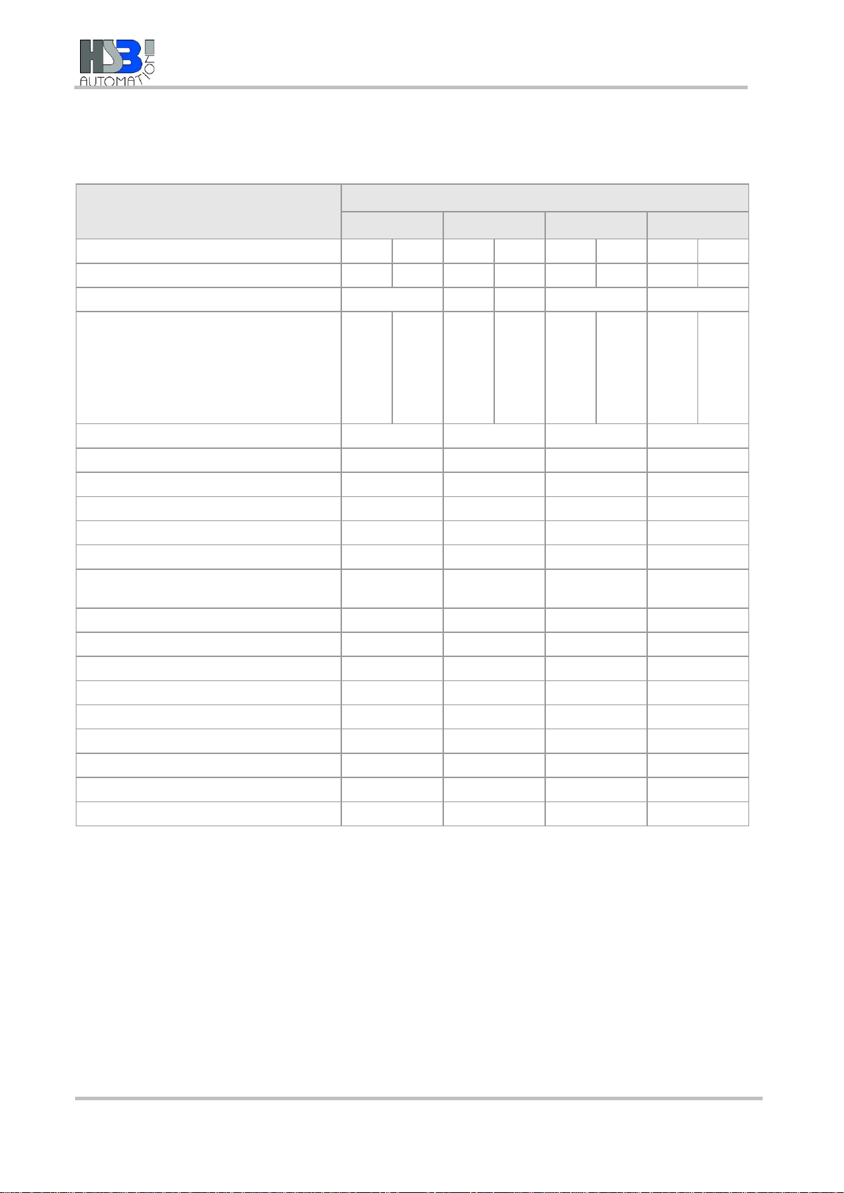
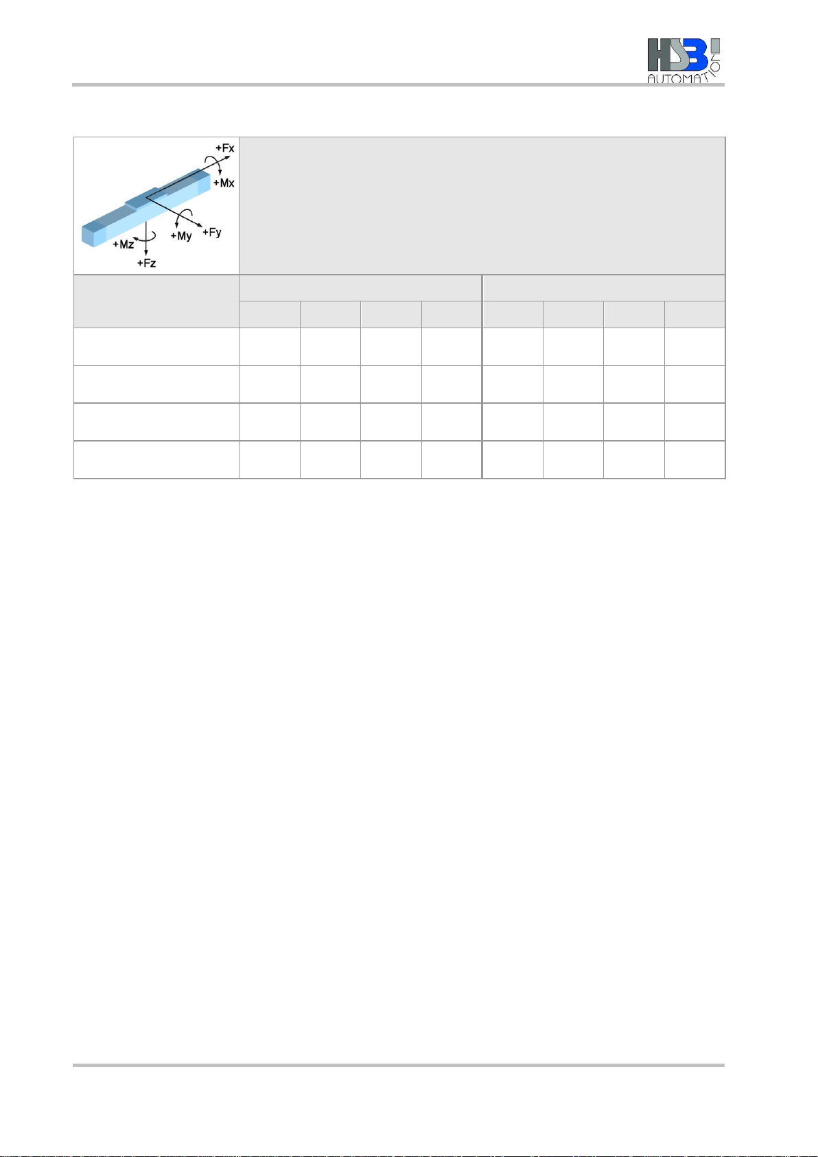
3Technical data –Standard model...........................................................................7
4Product description...............................................................................................11
5Transportation and storage ..................................................................................14
6Installation and adjustment...................................................................................15
6.1 Mounting the linear unit by the base plate................................................................ 15
6.2 Screwing the linear unit into place from below......................................................... 16
6.3 Setting maximum travel........................................................................................... 16
6.3.1 Setting the positions of the inductive limit switches ..................................17
6.3.2 Setting the positions of the mechanical limit switches...............................19
6.4 Mounting a drive unit ............................................................................................... 20
6.4.1 Mounting a motor.....................................................................................21
7Start-up...................................................................................................................22
8Operation................................................................................................................24
9Shutdown................................................................................................................25
10 Maintenance...........................................................................................................26
10.1 Lubrication............................................................................................................... 26

Safety
22021-03-25 FM 241 MuW Alpha Type S Rev.01
1 Safety
The Assembly and Maintenance Manual is a component element of the
product package, and must always be kept to hand as a reference
source.
The Manual must be passed on if the unit is sold on or given away.
If there is anything in this manual which you do not fully understand,
please be sure to contact the manufacturers.
1.1 Symbols used
This Assembly and Maintenance Manual employs the following
symbols to indicate hazards as well as other types of symbol:
Indicates immediate danger.
Failure to observe this notice entails risk of death or very serious injury.
Indicates a danger carrying a medium to high risk.
Failure to observe this notice may result in death or serious injury.
Indicates minor risk.
Failure to observe this notice may result in light to moderate injury or
damage to property.
Note
Indicates tips on use of the machine and optimising its efficiency.
1.2 Regulation use
The mechanical linear unit is intended for installation in machines, and
is used solely for manipulating, positioning, transporting, palletising,
loading, unloading, clamping, clocking, tensioning, testing, measuring,
handling and pushing workpieces or tools.
Pay attention to the basic applications of the linear unit set out in
sections 4 and 3.
In order to comply with the EU Directive governing Electromagnetic
Compatibility (EMC), the mechanical linear unit may only be used in
industrial environments.
Any other use, or use for purposes beyond those stipulated, will be
classed as illegitimate. The manufacturers accept no liability for any
loss thereby incurred. The risk is borne solely by the operators.

Safety
FM 241 MuW Alpha Type S Rev.01 2021-03-25 3
1.3 General safety
Preconditions for
operation
The linear unit must not be put into operation until the machine or line
into which it is installed conforms to the following:
•Relevant accident prevention regulations
•Generally accepted safety standards
•EU directives
•Standards governing the electromagnetic compatibility of machinery
•Other applicable standards
•Applicable national legislation.
Safe operation
To ensure safe operation, refer to the following documents:
•This operating manual for the linear unit, particularly the technical
data
•The operating manual for the line into which it is installed
1.4 Use in explosive environments
If the linear units are used in potentially explosive environments,
operators must take steps to prevent explosions in accordance with
ATEX Directive 2014/34/EU and ensure explosion-proofing is installed.
The following ATEX rules must be observed:
•Operators must check the linear unit at least once a week, and
ideally every day. The checks should cover: smooth running,
functionality of all seals, and adequate lubrication.
•After a mileage of approx. 5000 km, but at least every 24 months,
the functionality of the linear unit must be checked by a qualified
expert.
•The operator/manufacturer of the end-product must ensure that the
linear unit is integrated into the potential equalisation system of the
overall plant at the ports provided for the purpose. Where the unit is
used in a dust-explosion hazard zone, the compressed air supply
must additionally be connected to the linear unit.
•The limit switches must be supplied via an isolating amplifier. For
the EX isolation an intrinsically safe input circuit is required. The
isolating amplifier is not supplied by HSB.
•The linear unit may only be used under the conditions approved by
the manufacturer. They include:

Safety
42021-03-25 FM 241 MuW Alpha Type S Rev.01
−Ambient temperature
−Ambient conditions
−Speed < 1 m/s;
Speeds > 1 m/s only in combination with monitored central
lubrication; operation in areas with potentially explosive dust
possible with additional monitored compressed air loading
−Maximum acceleration
−Duty cycle
−Load etc.
1.5 Technical condition of the linear unit
State of the art
The unit conforms to the current state of the art and applicable rules
and regulations. The unit conforms to the EU Machinery Directive,
harmonised European standards or corresponding national standards:
•Machinery Directive 2006/42/EC
•EN ISO 12 100:2011-03: Safety of Machinery, General Design
Guidelines, Risk Assessment and Reduction
•EN ISO 13850:2008-09: Safety of machinery; emergency-stop
devices
•DIN EN 60 204-1:2006: Electrical equipment for industrial machines
•2004/108/EC: EMC Directive
•EMVG: German law relating to the electromagnetic compatibility of
equipment dated 26.02.2008 (Federal Gazette I p. 220)
1.6 Modifications to the linear unit
Modifications
The linear unit must not be modified, either in its basic design or in its
safety components, without our written consent. Any such unauthorised
modification will void our liability in respect of the unit.
The operating company may only carry out the maintenance and repair
work detailed in this operating manual. Any other measures, such as to
replace wearing parts and components, may be carried out only in
consultation with our service engineers, by the service engineers
themselves, or by us directly.
Installed safety devices must never be dismantled or disabled.
When fitting special attachments to the unit, follow the fitting
instructions provided by the manufacturers!

Safety
FM 241 MuW Alpha Type S Rev.01 2021-03-25 5
1.7 Requirements for personnel
The linear unit has been designed and built in accordance with the
state of the art and accepted safety standards. Hazards may
nevertheless be posed when operating it. Consequently, the unit may
only be installed and operated by trained, competent personnel.
All personnel assigned to install, operate, maintain, repair or dismantle
a linear unit must have read and understood this operating manual, and
in particular section 1, “Safety”.
Work on parts carrying live electrical current may be carried out only by
trained electricians. Such work includes:
•Installing safety limit switches
•Mounting a drive unit
•Checking the direction of rotation of the drive
1.8 Obligations of the operating company
Instruction of
personnel
In accordance with EU Health and Safety Directive 89/655/EEC articles
6(1) and 7 and with the Framework Directive 89/391/EEC articles 1(1)
and 6(1), the company operating the linear unit must provide personnel
assigned to install, operate, maintain, repair or dismantle the unit with
appropriate instruction, in particular with regard to safety.
We recommend that companies require their personnel to provide
written confirmation of having received such instruction.
Checking the unit
In accordance with EU Health and Safety Directive 89/655/EEC article
4a, the operating company must subject to the unit to thorough
checking prior to putting it into operation, after carrying out repairs, and
after malfunctions have occurred.
Legibility and
maintenance of
affixed notices and
labels
The operating company must ensure that all notices and labels
attached to the unit are fully legible (in particular details of the serial
number) and must ensure compliance with all instructions contained on
them. Damaged or illegible notices and labels must be replaced.

Warranty
62021-03-25 FM 241 MuW Alpha Type S Rev.01
2 Warranty
The warranty conditions are laid down in the terms and conditions of
delivery and payment issued at time of order. Warranty cover will be
voided if:
•the unit is not operated in accordance with the stipulated regulation
use;
•the instructions set out in this operating manual are not followed;
•the unit is modified without the consent of the manufacturers;
•screws sealed by locking varnish are unlocked.
The manufacturer’s warranty in respect of maintenance and repair work
applies only if original replacement parts are used.

Technical data –Standard model
FM 241 MuW Alpha Type S Rev.01 2021-03-25 7
3 Technical data –Standard model
Technical data - Linear unit
Sizes
Alpha type with spindle drive
15-B-155
20-B-225
30-B-325
35-B-455
Drive element
BSD2)
TSD3)
BSD
TSD
BSD
TSD
BSD
TSD
Max. speed [rpm]
3000
1500
3000
1500
3000
1500
3000
1500
Spindle diameter [mm]
20
25
24
32
40
Spindle pitch [mm]
5
10
20
20 long
50
4
8
16
5
5 long
10
10 long
25
25 long
50
5
10
5
10
20
40
6
5
10
20
40
7
Moment of inertia [kgm²/m]
8.50 x 10⁻⁵
2.25 x 10⁻⁴
6.45 x 10⁻⁴
1.65 x 10⁻³
Max. velocity1) [m/s]
1,00
2,00
2,00
2,00
Max. acceleration [m/s2]
20
20
20
20
No-load torque [Nm]
0,35
0,50...1,20
0,50...2,50
0,50...2,50
Maximum travel (standard) [mm]
1235
1645
2540
2420
Repeat accuracy [mm]
±0,03
±0,03
±0,03
±0,03
Operating temperature [°C] (continuous
operation)
0 ... 80
0 ... 80
0 ... 80
0 ... 80
Geometrical moment of inertia IY[mm4]
133830
359736
774301
1810370
Geometrical moment of inertia IZ[mm4]
5816886
22821235
84507566
284741450
Length of standard carriage [mm]
150
220
320
450
Length of long carriage [mm]
220
320
450
600
Weight (without travel) [kg]
7,80
17,60
37,00
65,20
Weight (per 100 mm travel) [kg]
0,95
2,70
3,80
5,20
Weight of standard carriage [kg]
2,80
6,20
13,40
26,20
Weight of long carriage [kg]
4,10
9,00
18,80
33,80
Noise emission max. [dB A] 4)
80
80
80
80
1) Dependent on spindle pitch at max. speed
2) Ball Screw Drive
3) Trapezoidal Screw Drive
4) The figure will vary based on assembly with other system components

Technical data –Standard model
82021-03-25 FM 241 MuW Alpha Type S Rev.01
Forces and moments - Alpha linear unit with spindle drive
Type designation
Dynamic forces [Nm]
Dynamic moments [Nm]
FX
FY
FZ
-FZ
MX
MY
MZ
Mno-load
Alpha 15-B-155
4000
2000
20000
15000
1000
900
(1300)
400 (580)
0,35
Alpha 20-B-225
6000
5000
58000
40000
4000
3000
(4000)
1200
(1700)
1,2
Alpha 30-B-325
12000
11000
95000
63000
6300
7500
(9500)
3750
(5000)
1,6
Alpha 35-B-455
18000
14000
120000
80000
12000
10000
(13000)
5000
(6000)
2,5
Figures in ( ) relate to the long carriage.
Mno-load = No-load torque ±30 %
The forces and moments quoted are maximum values for the single load. In the event
of combined loading or simultaneous occurrence of multiple moments or forces, the
individual values must be reduced. In case of doubt consult Technical Support.

Technical data –Standard model
FM 241 MuW Alpha Type S Rev.01 2021-03-25 9
Dynamic load ratings of ball screw drives - Alpha linear unit
Model and size
Nominal Ø in
[mm]
Pitch in [mm]
Cdyn [N]
Alpha 15-B-155
20
5
14600
10
13500
20
11500
20 long
23900
50
12300
Alpha 20-B-225
25
5
16100
5 long
23300
10
15100
10 long
22300
25
15800
25 long
32700
50
14500
Alpha 30-B-325
32
5
26200
10
33100
20
30200
40
15200
Alpha 35-B-455
40
5
29100
10
50000
20
37900
40
37000
Dynamic load rating of ball screw nut to DIN 69051, 1989
Dynamic load ratings of rail guides - Alpha linear unit
Model
Size
Number
of rails
Number of
carriages
Load rating
per carriage
Cdyn [N]
THK / Rex*
Pretension
FV
[N]
THK / Rex*
Mt
[Nm]
Guide
spacing in
direction x
(lx1) [mm]
Guide
spacing in
direction y
(ly) [mm]
Alpha 15-B
15
2
4
11271 / 9860
564 / 620
-
94 (164)
105
Alpha 20-B
20
2
4
17700 / 23400
885 / 1500
-
143 (243)
160
Alpha 30-B
30
2
4
35558 / 36500
1778 / 2540
-
205 (335)
240
Alpha 35-B
35
2
4
49448 / 51800
2472 / 4450
-
286 (436)
340
Figures in ( ) relate to the long carriage
The load rating and pre-tension figures relate to the standard linear guidance system with recirculating linear ball
bearings
* Rex = Rexroth

Technical data –Standard model
10 2021-03-25 FM 241 MuW Alpha Type S Rev.01
Tightening torques [Nm] for fixing screws
Fixing screws
M4
M5
M6
M8
M10
M12
M16
The figures given are intended as
guides.
For shorter insertion depths, the
figures must be adjusted
accordingly.
DIN912/ISO4762-8.8
2,7
5,4
9,0
22,0
43,0
74,0
120,0
DIN912/ISO4762-10.9
3,0
5,7
9,0
22,0
43,0
74,0
120,0
DIN912/ISO4762-12.9
3,0
5,7
9,0
22,0
43,0
74,0
120,0
Tightening torques [Nm] for clutch with clamping hub
Size
14
19
24
28
38
Clutch diameter [mm]
30
40
55
65
80
Screw size
M3
M6
M6
M8
M8
Tightening torque [Nm]
1.34
10.50
10.50
25.00
25.00
Tightening torques [Nm] for clutch with clamping ring hub
Size
14
19
24
28
38
Clutch diameter [mm]
30
40
55
65
80
Screw size
M3
M4
M5
M5
M6
Tightening torque [Nm]
1.34
2.90
6.00
6.00
10.00

Product description
FM 241 MuW Alpha Type S Rev.01 2021-03-25 11
4 Product description
Linear unit with
spindle drive and rail
guidance
Key
1
Carriage
4
Base profile
2
Bellows (optional)
5
Lubricating nipple
3
Movable bearing
6
Fixed bearing
Figure 1: Component assemblies of the Alpha 20-B linear unit with spindle
drive

Product description
12 2021-03-25 FM 241 MuW Alpha Type S Rev.01
Key
7
Nut driver
12
Carriage
9
Inductive limit switch
13
Mechanical limit switch
10
Thread drive
11
Guide rail
Figure 2: Component assemblies of the Alpha 20-B linear unit with spindle
drive

Product description
FM 241 MuW Alpha Type S Rev.01 2021-03-25 13
A mechanical linear unit converts rotational motion into linear motion
and is used to move loads quickly, safely and precisely from one
position to another. It consists of an aluminium base profile, a moving
carriage supported by a guide element (recirculating ball bearing or
roller bearing guidance system) and a drive element (screw or timing
belt drive).
Depending on its design, the carriage is able to absorb forces and
moments in all directions, and is positively connected to the guidance
and drive elements by way of the so-called drivers.
The base profile is self-supporting up to a certain length, and is
equipped with grooves for mounting.
As an option, the linear unit can be equipped with accessories such as
a cover, screw supports, inductive or mechanical limit switches and
other fittings(see section 6.3).
The effective range can be flexibly configured. Multiple linear units of
the Alpha, Beta or Delta type can be arranged two-dimensionally (2
axes) or three-dimensionally (3 axes).
Driven linear units can be connected to non-driven units of the same
type by a plate, to be able to take large-area loads for example.

Transportation and storage
14 2021-03-25 FM 241 MuW Alpha Type S Rev.01
5 Transportation and storage
The mechanical linear unit is a precision item. Its mechanism may be
damaged by heavy jolting, resulting in impairment of its functions.
Risk of damage by heavy jolting or bending!
Transport the assembled linear unit only with the transit protection
fitted.
To prevent damage during transportation and storage, protect the linear
unit against shaking and sliding as follows:
•Stow it in a box of sufficient size.
•Use packing.
Section 3 lists the unit weights.
Protect the unit against:
•dirt;
•corrosion;
•water;
•and aggressive atmospheres.

Installation and adjustment
FM 241 MuW Alpha Type S Rev.01 2021-03-25 15
6 Installation and adjustment
The linear unit can be attached by the following methods:
•By screws through the holes in the base plate
•By screws inserted into the sliding blocks
•By screws inserted into the factory-fitted tapped hole rails
Install the linear unit on a flat surface. Unit parallelism < 0.2
mm/1,000 mm.
Mounting by the rails with tapped holes in them is the preferable
solution:
for highly dynamic applications;
where the linear unit has only two attachment points.
6.1 Mounting the linear unit by the base plate
Figure 3: Mounting holes with setscrew (1) and fixing holes (2)
Procedure
1. Align the linear unit axially.
2. Run the carriage all the way to the right and then to the left (figure 3).
3. Fit the screws through the accessible fixing holes (2) into the
mounting panel (for tightening torques see section 3).
4. Unscrew the setscrews from the mounting holes (1)
5. Move the carriage so that the remaining fixing holes are accessible
through the mounting holes (1) and fit the screws.
6. Lock the mounting holes (1) with the setscrews (to protect against
dirt intrusion).

Installation and adjustment
16 2021-03-25 FM 241 MuW Alpha Type S Rev.01
6.2 Screwing the linear unit into place from below
Figure 4: Sliding blocks (1) in the groove on the underside of the base profile
Attach the linear unit by the fixing screws from below using the sliding
blocks or the tapped hole rails in the aluminium profile (figure 4).
Procedure
1. Align the linear unit.
2. Align the sliding blocks (1)/tapped hole rails.
3. Tighten the linear unit
(for tightening torques see section 3).
6.3 Setting maximum travel
Serious injury may result if the transport carriers topple over.
If the carriage moves to its full extent beyond the safety zone, the
transport carrier mounted on it may break away or topple over. The
linear unit may be destroyed
During setup, define a safety zone and set the limit switches
accordingly.
Electrical switches may only be connected by qualified electricians.
To stop the carriage promptly in the event of an emergency stop,
allow for adequate braking distance.

Installation and adjustment
FM 241 MuW Alpha Type S Rev.01 2021-03-25 17
6.3.1 Setting the positions of the inductive limit switches
The function of inductive proximity switches is to shut down the electric
drive before the mechanical end position is reached.
The necessary braking distance depends on the velocity and
deceleration of the carriage base. The braking distance must be
between the switching point of the proximity switch and the actual
mechanical end position.
Type Alpha 15-B
Key
1
Switching cam
2
Inductive limit switch
Figure 5: Inductive limit switches for type Alpha 15-B
The limit switches must switch in such a way that the carriage does not
run all the way to the stop and so that the bellows are not squashed.
Procedure
Setting for type Alpha 15-B
1. Connect the power to the limit switches.
2. Slacken the fixing screws of the relevant limit switch (figure 5).
3. Run the carriage as far as the braking position.
4. Move the limit switch (NC contact) under the switching cam until it
trips and the LED on the sensor goes out.
5. Move the carriage away.
6. Tighten the limit switch.
7. Check the correct position of the limit switch: Move the carriage
manually and observe the switching operation.
8. Fit the limit switch array covering.

Installation and adjustment
18 2021-03-25 FM 241 MuW Alpha Type S Rev.01
As from type Alpha
20-B
Key
1
Inductive limit switch
2
Bearing
Figure 6: Inductive limit switches for types Alpha 20-B, 30-B, 35-B
The limit switches must switch in such a way that the carriage does not
run all the way to the stop and so that the bellows are not squashed.
Procedure
Setting for types Alpha 20-B, 30-B, 35-B
1. Connect the power to the limit switches.
2. If bellows are fitted, unscrew their mounting plates from the
carriage. Push the bellows onto the bearings.
3. Move the carriage so that the desired limit switch is accessible
(figure 6).
4. Slacken the limit switch fixing screws.
5. Run the carriage as far as the braking position.
6. Move the limit switch (NC contact) under the switching element until
it trips and the LED on the sensor goes out.
7. Tighten the limit switch.
8. Check the correct position of the limit switch: Move the carriage
manually and observe the switching operation.
9. Re-attach the bellows with the mounting plates to the carriage.
This manual suits for next models
3
Table of contents
Other HSB Industrial Equipment manuals
Popular Industrial Equipment manuals by other brands

CHART
CHART Nomad 830G MP product manual

Finmeccanica
Finmeccanica Selex ES Radom650C Service manual

Huaqi Zhengbang
Huaqi Zhengbang ZB3245TSS user manual

Sonny's
Sonny's Pendulum 807W Combo owner's manual

PCB Piezotronics
PCB Piezotronics 352A24/NC Installation and operating manual

MADDALENA
MADDALENA ArrowWAN MVM wM-Bus 169 Instructions for installation, use and maintenance