HT VEGA74 User manual

©Copyright HT ITALIA 2022 Release EN 1.00 - 16/11/2022
VEGA74
User manual

VEGA74
EN - 1
TABLE OF CONTENTS
1. PRECAUTIONS AND SAFETY MEASURES...............................................................3
1.1. Preliminary instructions..................................................................................................... 3
1.2. During use......................................................................................................................... 4
1.3. After use............................................................................................................................ 4
1.4. Definition of measurement (overvoltage) category............................................................ 4
2. GENERAL DESCRIPTION...........................................................................................5
2.1. Foreword........................................................................................................................... 5
3. PREPARATION FOR USE...........................................................................................6
3.1. Initial checks...................................................................................................................... 6
3.2. Instrument power supply................................................................................................... 6
3.3. Storage.............................................................................................................................. 6
4. NOMENCLATURE........................................................................................................7
4.1. Instrument description....................................................................................................... 7
4.2. Description of measuring leads......................................................................................... 7
4.3. Keyboard description......................................................................................................... 8
4.4. Display description............................................................................................................ 8
4.5. Initial screen...................................................................................................................... 8
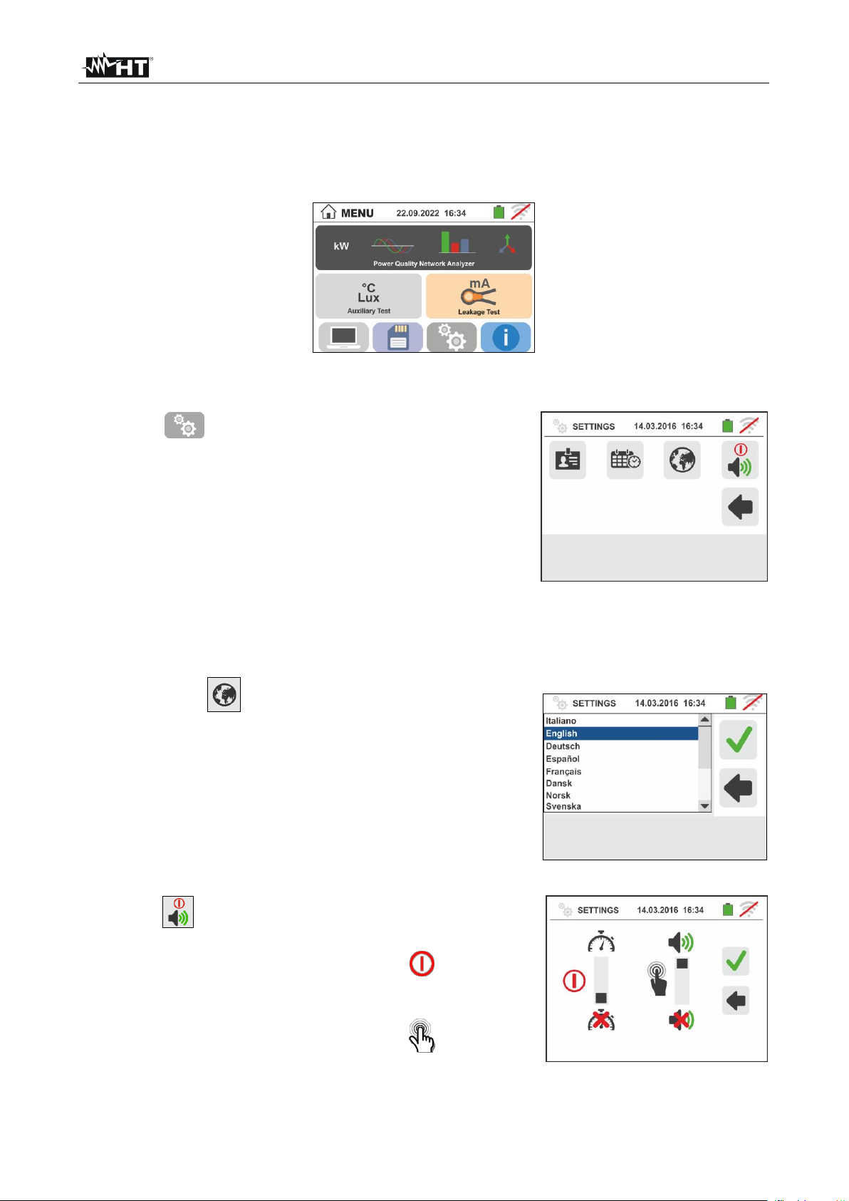
5. GENERAL MENU.........................................................................................................9
5.1. Instrument settings............................................................................................................ 9
5.1.1. Language................................................................................................................................. 9
5.1.2. Automatic Power OFF for display and key sound.................................................................... 9
5.1.3. Operator name entry.............................................................................................................. 10
5.1.4. System date/time setting........................................................................................................ 10
5.2. Information ...................................................................................................................... 10
6. OPERATING INSTRUCTIONS...................................................................................11
6.1. LEAKAGE: Leakage current measurement and recording.............................................. 11
6.2. AUX: Measure and recording of ambient parameters..................................................... 14
6.3. PQA: Measurement and recording of main parameters.................................................. 17
6.3.1. Connections types ................................................................................................................. 17
6.3.2. General settings..................................................................................................................... 21
6.3.3. Display of measurements ...................................................................................................... 23
6.3.4. Start recording........................................................................................................................ 25
6.4. List of message at display............................................................................................... 27
7. OPERATIONS WITH THE MEMORY.........................................................................28
7.1. Saving measurements..................................................................................................... 28
7.1.1. Saving snapshots................................................................................................................... 28
7.1.2. Recalling and deleting snapshots.......................................................................................... 29
7.1.3. Recall and delete saved recordings....................................................................................... 30
7.1.4. Anomalous situations............................................................................................................. 31
8. CONNECTING THE INSTRUMENT TO A PC............................................................32
9. MAINTENANCE .........................................................................................................33
9.1. General information......................................................................................................... 33
9.2. Recharging and replacement of the batteries ................................................................. 33
9.3. Cleaning the instrument .................................................................................................. 33
9.4. End of life ........................................................................................................................ 33
10. TECHNICAL SPECIFICATIONS ................................................................................34
10.1. Technical characteristics AUX AND LEAKAGE sectionS ............................................... 34
10.2. Technical characteristics PQA section............................................................................ 35
10.3. Reference guidelines....................................................................................................... 37
10.4. General characteristics.................................................................................................... 37
10.5. Environment.................................................................................................................... 37
10.5.1. Environmental conditions for use........................................................................................... 37
10.6. Accessories..................................................................................................................... 37
11. SERVICE....................................................................................................................38
11.1. Warranty conditions......................................................................................................... 38

VEGA74
EN - 2
11.2. Service ............................................................................................................................ 38
12. THEORETICAL APPENDIXES...................................................................................39
12.1. Voltage Anomalies .......................................................................................................... 39
12.2. Supply voltage unbalance............................................................................................... 39
12.3. Voltage and current Harmonics....................................................................................... 40
12.4. Definitions of powers and power factors ......................................................................... 43
12.5. Measuring method: outlines............................................................................................ 46
12.6. Description of typical configurations................................................................................ 47

VEGA74
EN - 3
1. PRECAUTIONS AND SAFETY MEASURES
The instrument is been designed in compliance with directives IEC/EN61557 and
IEC/EN61010-1, relevant to electronic measuring instruments. Before and after carrying
out measurements, carefully observe the following instructions:
•Do not carry out any voltage or current measurement in humid environments.
•Do not carry out any measurements in case gas, explosive materials or flammables are
present, or in dusty environments.
•Avoid any contact with the circuit being measured if no measurements are being
carried out.
•Avoid contact with exposed metal parts, with unused measuring probes, etc.
•Do not carry out any measurement in case you find anomalies in the instrument such
as deformations, breaks, substance leaks, absence of display on the screen, etc.
•Pay special attention when measuring voltages higher than 25V in special
environments (such as construction sites, swimming pools, etc.) and higher than 50V in
normal environments, since a risk of electrical shock exists.
•Only use original HT accessories.
The following symbols are used in this manual:
CAUTION: observe the instructions given in this manual; improper use could
damage the instrument, its components or create dangerous situations for the
operator.
High voltage danger: electrical shock hazard.
Double insulation
AC voltage or current
DC voltage or current
Connection to earth
1.1. PRELIMINARY INSTRUCTIONS
•This instrument has been designed for use in the environmental conditions specified in
§ 10.5.1. Do not use in different environmental conditions.
•The instrument may be used for measuring and verifying the safety of electrical
systems. Do not use on systems exceeding the limit values specified in § 10.4.
•We recommend following the normal safety rules devised to protect the user against
dangerous currents and the instrument against incorrect use.
•Only the accessories supplied with the instrument (in particular the external adapter
A0061) guarantee compliance with safety standards. They must be in good conditions
and be replaced with identical models, when necessary.
•Make sure the batteries are correctly installed.
•Before connecting the test leads to the circuit being measured, check that the desired
function has been selected

VEGA74
EN - 4
1.2. DURING USE
Please carefully read the following recommendations and instructions:
CAUTION
Failure to comply with the caution notes and/or instructions may damage
the instrument and/or its components or be a source of danger for the
operator.
•Before changing function, disconnect the test leads from the circuit under test.
•When the instrument is connected to the circuit under test, never touch any terminal,
even if unused.
•Avoid measuring resistance if external voltages are present. Even if the instrument is
protected, excessive voltage could cause damage.
•While measuring current, place the clamp jaws as far as possible from the conductors
not involved in the measurement, as the magnetic field they produce could interfere
with the measuring operations and place the conductor as much as possible in the
center of the jaws to maximize accuracy.
1.3. AFTER USE
When measurements are completed, turn off the instrument by pressing and holding the
ON/OFF key for some seconds. If the instrument is not to be used for a long time, remove
the batteries and follow the instructions given in § 3.3.
1.4. DEFINITION OF MEASUREMENT (OVERVOLTAGE) CATEGORY
Standard "IEC/EN61010-1: Safety requirements for electrical equipment for measurement,
control and laboratory use, Part 1: General requirements” defines what measurement
category, commonly called overvoltage category, is. § 6.7.4: Measured circuits, reads:
circuits are divided into the following measurement categories:
•Measurement Category IV is for measurements performed at the source of a low-
voltage installation.
Examples are electricity meters and measurements on primary overcurrent protection
devices and ripple control units.
•Measurement Category III is for measurements performed on installations inside
buildings.
Examples are measurements on distribution boards, circuit breakers, wiring, including
cables, bus-bars, junction boxes, switches, socket-outlets in fixed installation, and
equipment for industrial use and some other equipment, for example, stationary motors
with permanent connection to fixed installation.
•Measurement Category II is for measurements performed on circuits directly
connected to the low-voltage installation.
Examples are measurements on household appliances, portable tools and similar
equipment.
•Measurement Category I is for measurements performed on circuits not directly
connected to MAINS.
Examples are measurements on circuits not derived from MAINS, and specially
protected (internal) MAINS-derived circuits. In the latter case, transient stresses are
variable; for that reason, the standard requires that the transient withstand capability of
the equipment is made known to the user.

VEGA74
EN - 5
2. GENERAL DESCRIPTION
2.1. FOREWORD
The instrument is equipped with a TFT color LCD display, with capacitive "touch-screen"
that can be handled simply with the touch of a finger by the user and is structured with an
icon-based menu allowing the direct selection of measurement functions for quick and
intuitive use.
The instrument can perform the following tests:
PQA Real-time measurement and recording of mains parameters, harmonic
analysis, voltage anomalies (sags, swells), power/energy consumption
in single-phase and three-phase generic systems
AUX Measurement and recording of environmental parameters (illuminance, air
temperature, humidity) by means of optional external probes and DC voltage
signals
LEAKAGE Measurement and recording of leakage current (by means of the
optional transducer clamp HT96U)

VEGA74
EN - 6
3. PREPARATION FOR USE
3.1. INITIAL CHECKS
Before shipping, the instrument has been checked from an electric as well as mechanical
point of view. All possible precautions have been taken so that the instrument is delivered
undamaged. However, we recommend checking it to detect any damage possibly suffered
during transport. In case anomalies are found, immediately contact the Dealer. We also
recommend checking that the packaging contains all the components indicated in § 10.6.
In case of discrepancy, please contact the Dealer. In case the instrument should be
returned, please follow the instructions given in § 11.
3.2. INSTRUMENT POWER SUPPLY
The instrument is powered by 6x1.2V NiMH rechargeable batteries type AA LR06 supplied
with the instrument or by 6x1.5V alkaline batteries type AA LR06. Rechargeable batteries
must be recharged by using the external charger A0061, also provided with the instrument.
The green “ ” symbol indicates a sufficient charge level for the correct performance of the
tests. The red “ ” symbol indicates an insufficient charge level for the correct performance
of the tests. In this case, recharge the batteries (see § 9.2).
CAUTION
•If the external adapter is used, it is necessary to connect it first to the
instrument, then to the mains, then please connect the instrument to the
circuit to be tested
•While recording it is recommended to use both the external adapter and
the rechargeable batteries, in order to guarantee the instrument’s supply
in case of voltage interruption
•With low battery indication, stop the tests and recharge or replace the
batteries (see § 9.2)
•The instrument is capable of keeping data stored even without batteries
•The instrument has an AutoPower OFF function (which can be
deactivated) after 5 minutes’ idling (the Auto Power OFF is inactive while
recording –see § 5.1.2)
3.3. STORAGE
In order to guarantee precise measurement, after a long storage time under extreme
environmental conditions, wait for the instrument to come back to normal condition (see §
10.5.1).

VEGA74
EN - 7
4. NOMENCLATURE
4.1. INSTRUMENT DESCRIPTION
CAPTION:
1. Inputs
2. LCD Touch screen display
3. Function keys F1, F2, F3, F4
4. ,, , / ENTER keys
5. Compartment of the connector
for optical cable/USB port
6. ESC key
7. GO/STOP key
8. HELP key
9. SAVE key
10.ON/OFF key
Fig. 1: Description of the front part of the instrument
CAPTION:
1. B1, B2, B3, B4 inputs
2. I1, I2, I3, I4 inputs
Fig. 2: Description of the upper part of the instrument
CAPTION:
1. Connector for external adapter
2. Connector for optical/USB cable
Fig. 3: Description of the instrument's side
4.2. DESCRIPTION OF MEASURING LEADS
CAPTION:
1. Hand protection
2. Safe area
Fig. 4: Description of measuring leads

VEGA74
EN - 8
4.3. KEYBOARD DESCRIPTION
The keyboard includes the following keys:
ON/OFF key to switch on/off the instrument
ESC key to exit the selected menu without confirming
keys to move the cursor through the different screens in order
to select the desired programming parameters
HOME / ENTER key to back to general Menu on each moment
GO/STOP key to start the measurement
SAVE key to save the measured values
HELP key to access the online help and display the possible connections
between the instrument and the system for each selected function
F1, F2, F3, F4
Function keys corresponding to the activation of the four icons on the
bottom of the screen as an alternative to direct touch on the display
4.4. DISPLAY DESCRIPTION
The display is an LCD, 320x240pxl TFT color display with
capacitive touch screen whose icon-structure can be directly
selected with a simple touch. The first line of the display
indicates the type of active measurement, the date/time and
the battery charge indication.
4.5. INITIAL SCREEN
When switching on the instrument, the initial screen appears
for a few seconds. It shows:
➢The HT manufacturer's logo
➢The instrument model
➢The Firmware version (LCD and CPU)
➢The serial number (SN:) of the instrument
➢The date of instrument calibration (Calibration date:)
After a few seconds, the instrument switches to the general menu.

VEGA74
EN - 9
5. GENERAL MENU
Pressing the ENTER key in any condition of the instrument allows to go back to the
general menu in which internal parameters may be set, the saved measures can be
displayed and the desired measuring function may be selected.
Fig. 5: General menu of the instrument
5.1. INSTRUMENT SETTINGS
Touch the icon. The screen to the side appears on
the display. The following settings are available:
➢System language setting
➢System date/time setting
➢Operator name setting
➢Activation/deactivation of display AutoPower OFF and
of key sound
Settings will be maintained also after switching off the
instrument.
5.1.1. Language
Touch the icon to select the system language. The
screen to the side appears on the display.
Select the desired language, confirm the choice and return
to the previous screen.
5.1.2. Automatic Power OFF for display and key sound
Touch the icon. The screen to the side appears on the
display.
Move the slide bar reference of section " " down/up to
turn off/on the Automatic Power OFF of the instrument after
a period of inactivity of 5 minutes.
Move the slide bar reference of section " " down/up to
disable/enable the sound key when pressed. Confirm the
choices made and go back to the previous screen.

VEGA74
EN - 10
5.1.3. Operator name entry
Touch the icon to enter the name of the operator that
will be displayed in the header of each measurement
downloaded to PC. The screen to the side appears on the
display.
➢Set the desired name using the virtual keyboard (max 12
characters).
➢Confirm the settings or exit without saving.
5.1.4. System date/time setting
Touch the icon to set the system date/time. The screen
to the side appears on the display.
Touch the "EU" icon for the European date/time system in
the format "DD/MM/YY hh:mm" or the "US" icon for the
American system in the format "MM/DD/YY hh:mm AM/PM".
Touch the up/down arrow keys to set the desired value.
Confirm the settings or exit without saving.
Current date/time is kept inside the instrument without
batteries for approximately 12 hours.
5.2. INFORMATION
Touch the icon . The display shows the screen on the
right with the icon relative to the properties of the
instrument
Touch the icon . The display shows the screen on the
right as well as following informations:
➢Serial number
➢Internal version of Firmare and Hardware
➢Last calibration date

VEGA74
EN - 11
6. OPERATING INSTRUCTIONS
6.1. LEAKAGE: LEAKAGE CURRENT MEASUREMENT AND RECORDING
This function allows measuring and recording the leakage current in single-phase or three-
phase systems by means of the optional accessory HT96U clamp.
Fig. 6: Indirect measurement of leakage current in three-phase systems
Fig. 7: Direct measurement of leakage current in three-phase systems
1.
Touch the icon. The screen to the side
appears on the display.
Touch the icon to set the full scale of the used
clamp. The following screen appears on the display:
2.
Touch the arrow keys or to set the full scale
value of the selected HT96U clamp in the 1A ÷ 3000A
range. Press and hold the keys for a quick selection of
values
Touch the icon to set recording parameters. The
following screen appears on the display
:

VEGA74
EN - 12
3.
Move the left slide bar cursor in order to select the
aggregation time (see § 12.5) among the options: 2s,
5s, 10s, 30s, 1min, 2min, 5min, 10min, 15min, 30min
Move the central slide bar cursor (“GO” symbol) to the
positions:
➢→Manual start of recording by pressing the
GO/STOP key (at the next minute after the pressure
of key)
➢→Automatic start of recording at the date/time
set by the user (after a preliminary pressure of
GO/STOP key in order to set the instrument in
stand-by mode). Touch the corresponding field to
set the date/time in the “MM:DD:YY HH:MM”
format and confirm
Move the right slide bar cursor (“STOP” symbol) in the
positions:
➢→Manual stop of recording by pressing the
GO/STOP key
➢→Automatic stop of recording at the date/time
set by the user. Touch the corresponding field to
set the date/time in the “MM:DD:YY HH:MM”
format and confirm
4.
Insert the external clamp into instrument input I1
5.
For indirect measurements of leakage current, connect the external clamp according to
Fig. 6. For direct measurements of leakage current, connect the clamp according to Fig.
7 and disconnect possible additional earth connections that could influence the test
results.
CAUTION
Possible additional earth connections could influence the measured value. In
case of real difficulty in removing them, we recommend performing the
measurement in an indirect way.
6.
The real time value of the measured leakage current
(Irms) and it’s maximum value (Imax) appears on the
display as shown in the screen to the side.
Press the SAVE button or touch the icon to save
the measurement (see § 7.1).

VEGA74
EN - 13
7.
Press the GO/STOP key to start recording. The
instrument enters stand-by mode (waiting for the next
minute or the set date/time) and the “ ” symbol is
displayed as shown in the screen to the side.
8.
With recording running, the “ ” symbol is displayed
as shown in the screen to the side.
Touch the “ ” icon to read in real time the
information about on-going recording. The following
screen appears on the display
9.
The screen contains:
➢The number of recording
➢The date/time of recording start (if automatic)
➢The date/time of recording stop (if automatic)
➢The aggregation time set
➢The number of aggregation intervals recorded
➢The residual memory capacity expressed in DD-HH-
MM
10.
Press GO/STOP key to stop recording; the instrument
automatically saves the result in its memory (see §
7.1.3). The message to the side is shown.
Confirm by touching the “ ” icon or touch the
“ ” icon to go back to the previous screen

VEGA74
EN - 14
6.2. AUX:MEASURE AND RECORDING OF AMBIENT PARAMETERS
By means of external transducers, this function allows measuring and recording the
following environmental parameters:
°C air temperature in °C by means of thermometric transducer
°F air temperature in °F by means of thermometric transducer
Lux(20) illuminance by means of luxmetric transducer with a 20Lux capacity
Lux(2k) illuminance by means of luxmetric transducer with a 2kLux capacity
Lux(20k) illuminance by means of luxmetric transducer with a 20kLux capacity
RH% air relative humidity by means of humidity transducer
mV input DC voltage (without applying any transduction constant)
Fig. 8: Measurement of environmental parameters through external probes
1.
Touch the icon . The screen to the side
appears on the display.
Touch the icon to set the type of measurement.
The following screen appears on the display:
2.
Move the slide bar reference to select the type of
measurement among the options: °C (temperature in
Celsius degrees), °F (temperature in Fahrenheit
degrees), Lux(20) (illuminance with 20Lux capacity),
Lux(2k) (illuminance with 2kLux capacity), Lux(20k)
(illuminance with 20kLux capacity) ,%RH (relative
humidity), mV (measurement of DC voltage up to 1V)
Touch the icon to set the parameters of
recording. The followed screen is shown

VEGA74
EN - 15
3.
Move the left slide bar cursor in order to select the
aggregation time (see § 12.5) among the options: 2s,
5s, 10s, 30s, 1min, 2min, 5min, 10min, 15min, 30min
Move the central slide bar cursor (“GO” symbol) to the
positions:
➢→Manual start of recording by pressing the
GO/STOP key (at the next minute after the pressure
of key)
➢→Automatic start of recording at the date/time
set by the user (after a preliminary pressure of
GO/STOP key in order to set the instrument in
stand-by mode). Touch the corresponding field to
set the date/time in the “MM:DD:YY HH:MM”
format and confirm
Move the right slide bar cursor (“STOP” symbol) in the
positions:
➢→Manual stop of recording by pressing the
GO/STOP key
➢→Automatic stop of recording at the date/time
set by the user. Touch the corresponding field to
set the date/time in the “MM:DD:YY HH:MM”
format and confirm
4.
Insert in the auxiliary I1 input the transducer necessary for the desired measurement as
shown in Fig. 8
5.
The measured value appears on the display in real time
as shown in the screen to the side.
Press the SAVE button or touch the icon to save
the measurement (see § 7.1).

VEGA74
EN - 16
6.
Press the GO/STOP key to start recording. The
instrument enters stand-by mode (waiting for the next
minute or the set date/time) and the “ ” symbol is
displayed as shown in the screen to the side.
7.
With recording running, the “ ” symbol is displayed
as shown in the screen to the side.
Touch the “ ” icon to read in real time the
information about on-going recording. The following
screen appears on the display
8.
The screen contains:
➢The number of recording
➢The date/time of recording start (if automatic)
➢The date/time of recording stop (if automatic)
➢The aggregation time set
➢The number of aggregation intervals recorded
➢The residual memory capacity expressed in DD-HH-
MM
9.
Press GO/STOP key to stop recording; the instrument
automatically saves the result in its memory (see §
7.1.3). The message to the side is shown.
Confirm by touching the “ ” icon or touch the
“ ” icon to go back to the previous screen

VEGA74
EN - 17
6.3. PQA: MEASUREMENT AND RECORDING OF MAIN PARAMETERS
In this section the instrument allows the below operations:
➢Real-time display of numeric values of any electrical parameters of a single-phase and
three-phase 3-wire or 4-wire system, harmonic analysis of voltages and currents up to
49th order, power/energies and power peaks absorbed/generated
➢Real-time display of any input signal waveform, histogram graphics of harmonics
analysis, vector diagrams of mutual angles between voltages and currents and voltage
unbalances
➢Recording (by pressing the GO/STOP key) of TRMS values of voltages, voltage
anomalies (sags, swells) with 20ms resolution, currents, corresponding harmonics,
active, reactive and apparent powers, power factors and cosphi, active, reactive and
apparent energies. It will be possible to analyze the recorded data ONLY by
transferring them onto a PC
Saving (by pressing the SAVE key) of an “Instant”sampling of instantaneous values of
any parameters present at instrument input in the instrument’s memory.
CAUTION
•The instrument can be used for measurements on installations with
overvoltage category CAT IV 300V to earth and max 600V between inputs.
Do not connect the instrument on installations with voltage exceeding the
limits indicated in this manual. Exceeding these limits could cause electrical
shock to the user and damage to the instrument.
•Always connect the measuring cables to the instrument and to the alligator
clips with the accessories disconnected from the system
•We recommend holding the alligator clip respecting the safety area created
by the hand protection (see § 4.2).
6.3.1. Connections types
The following types of electric systems can be selected in the instrument:
➢Three-phase system 3-4WIRES (three-phase + neutral + PE)
➢Three-phase system 3-3WIRES (three-phase without neutral + PE)
➢Three-phase system 3-ARON (three-phase + PE)
➢Single-phase system 1-2WIRES (phase + neutral)
➢Three-phase system 4-wires 3-High Leg –for USA country
➢Two-phase system 3-wires 3-Y Open –for USA country
➢Three-phase system 3-wires 3-Open –for USA country
➢Two-phase system 3-wires 3-2El. ½ –for USA country
➢Two-phase system 3-wires 1-CentrePoint –for USA country
Below, the connection schemes corresponging to the above-described situations are
reported:

VEGA74
EN - 18
Fig. 9: Connection for measurement on single-phase 1-2WIRES
Fig. 10: Connection for measurement on Three-phase system 3-4WIRES
Fig. 11: Connection for measurement on Three-phase system 3-3WIRES

VEGA74
EN - 19
Fig. 12: Connection for measurement on Three-phase system 3-ARON
Fig. 13: Connection for measurement on Three-phase system 4-wires 3-High Leg
Fig. 14: Connection for measurement on Three-phase system 3-wires 3-Open
Other manuals for VEGA74
1
Table of contents
Other HT Measuring Instrument manuals
Popular Measuring Instrument manuals by other brands

Eaton
Eaton Crouse-Hinds MTL Z230 instruction manual

VOLTCRAFT
VOLTCRAFT 2633254 operating instructions

Leica Geosystems
Leica Geosystems Rugby 640 quick start

Powerfix Profi
Powerfix Profi HG00384C Operation and safety notes

TRAP-IT
TRAP-IT ABD-075 Operation manual

Task Force Tips
Task Force Tips EF1 RC MONITOR Instructions for installation, safe operation and maintenance