Huato HE70X Series User manual

Operation Manual for HE70X/80X Series Multi-channel
thermocouple thermometer
Huato Electronic (Shenzhen) Co., LTD

CONTENTS
CONTENTS
CHAPTER 1. PRODUCTS INTRODUCTION......................................................................................................1
1.1BRIEFINSTRUCTIONSFORMULTI‐CHANNELTHERMOCOUPLETHERMOMETER........................................................................1
1.2MULTI‐CHANNELTHERMOCOUPLETHERMOMETERSMODELNUMBER.................................................................................2
1.3SINGLE‐CHANNELLCDDISPLAYINSTRUCTIONS(HE701,HE801).....................................................................................2
1.4TWO‐CHANNELLCDDISPLAYINSTRUCTIONS(HE702,HE802)........................................................................................4
1.5FOUR‐CHANNELLCDDISPLAYINSTRUCTIONS(HE704,HE804).......................................................................................5
1.6INSTRUCTIONSFORBUTTONSFUNCTION.........................................................................................................................6
CHAPTER 2 INSTRUCTIONS FOR SOFTWARE OPERATION.......................................................................7
2.1QUICKSTART............................................................................................................................................................7
2.2CONNECTINGTHETHERMOMETERDATALOGGERTOPC...................................................................................................7
2.3SETUPTHEATTRIBUTESOFTHETHERMOMETERDATALOGGER.............................................................................................8
2.4DOWNLOADDATAFROMTHETHERMOMETERDATALOGGER...............................................................................................9
2.5DELETEALLTHELOGSFROMTHETHERMOMETERDATALOGGER..........................................................................................9
2.6DATALISTINGWINDOW...........................................................................................................................................10
2.7EXPORTINGLOGSFROMTHERMOMETERDATALOGGER....................................................................................................11
2.8FILELIST................................................................................................................................................................11

PRODUCTS INTRODUCTION
---------P1--------
Chapter 1. Products Introduction
HE70X-80X series is thermocouple thermometer, developed by HUATO company, these series goes
through repeated professional testing and the mass production has proved the stability and the reliability.
It enjoys elegant appearance, large LCD display, backlight function and USB port telecommunication.
Besides, it can support 8 types thermocouple sensors (such as K, J, E, T, N, S, R, B), measuring -20degC
to 1800degC with different sensor type suitable for the exact applications. HE700-800 series with Huato
specialized Tespro software is easy to operate and quite convenient, widely applied in industrial
production fields, food processing industry, pharmaceutical industry and research testing fields as well as
other temperature monitoring applications.
1.1 Brief Instructions for Multi-channel Thermocouple Thermometer
(1) Buttons and instruments structure
LCD dis
p
la
y
Manual recordin
g
function button
Lo
g
button Model label
Setu
p
button USB
p
ort
ON/OFF Hole for fixed frame
OK button under the setup mode, and backlight
button under normal working mode Battery cover
Maximum and minimum checkin
g
buttons 701/801 ca
p
(sensor
p
ort)
Manual recordin
g
data checkin
g
button 702
/
802 ca
p
(sensor
p
ort)
The
p
revious data checkin
g
button 704/804 ca
p
(sensor
p
ort)

PRODUCTS INTRODUCTION
---------P2--------
1.2 Multi-channel Thermocouple Thermometers Model Number
Model Temperature
channel Measuring
accuracy Auto-Recording
(capacity)Manual-recording
(capacity)
HE701 1 ±0.1 ‰+0.5 -- 88
HE702 2 ±0.1 ‰+0.5 -- 88
HE704 4 ±0.1 ‰+0.5 -- 88
HE801 1 ±0.1 ‰+0.5 36000 88
HE802 2 ±0.1 ‰+0.5 36000 88
HE804 4 ±0.1 ‰+0.5 36000 88
Notice: The accuracy on the above table is only the accuracy for thermometer itself. The
precision in the practical applications has relation with the accuracy of thermocouple that
customers adopt. Please avoid adopting inferior thermocouple plug in case of any i terminal
damage to thermometers.
1.3 Single-channel LCD display instructions (HE701,HE801)
1
2
3
4
5
67
89
11
10
12
13
14
15
16
18
19
20
17

PRODUCTS INTRODUCTION
---------P3--------
Sensor type symbol display area. Capacity for auto-recording and
manual-recording data
Temperature data display area This symbol shows being the
manual-recording checking status
This symbol shows being the setup status Clock symbol
This symbol shows being the manual recording
data checking status Time display area
This symbol shows being the maximum and
minimum data checking status
This symbol shows instruments being
the connection status with PC.
This symbol shows being the holding fixed
measuring data status
Maximum and minimum data checking
buttons
This symbols shows that data can be deleted This symbol shows being the maximum
or minimum data checking status
This symbol shows instrument is supported
by external DC power Symbol for temperature unit
Battery status indication This symbol shows being the backlight
status
This symbols shows being the logging status This symbol shows the setting limits are
being exceeded

PRODUCTS INTRODUCTION
---------P4--------
1.4 Two-channel LCD display instructions (HE702,HE802)
12
4
5
3
67
8
10 11
12
13
14
9
15
16
17 18
This symbol shows being the setup mode This symbol shows being the
manual-recording data checking status
This symbol shows being the
maximum/minimum data checking status Symbol for clock
Sensor type symbol display area Year/month-date/clock alternate
display area
Symbol for channel 1 and channel 2 This symbol shows that instrument is
being connected with PC
This symbol shows that the setting limits for
channel 1 or channel 2 are being exceeded
Display area for channel 1 and channel
2
This symbol shows manual-recording data can
be deleted
Symbols for temperature unit for
channel 1 and channel 2
This symbol shows that the instrument is being
supported by DC external power
This symbol shows being the maximum
or minimum data checking status
Battery status indication This symbol shows being the holding
fixed measuring data status
This symbol shows being the logging status
Capacity for manual-recording or auto-recording
data

PRODUCTS INTRODUCTION
---------P5--------
1.5 Four-channel LCD display instructions (HE704,HE804)
12
3
4
5
67
8
10 11
12
13
14
9
16
17 18
15
This symbol showing being the setup mode This symbol shows being the
manual-recoding data checking status
This symbol shows being the maximum or
minimum data checking status Symbol for clock
Sensor type symbol display area Year/month-date/time alternate display
area
T1,T2,T3,T4 for channel 1, channel 2,
channel 3 and channel 4 respectively
This symbol shows that instrument is
being connected with PC
Data symbol for channel 1, channel 2,
channel 3 and channel 4
This symbol shows setting limits are
being exceeded
This symbol shows that manual-recording
data can be deleted
Temperature unit for channel 1, channel
2, channel 3 and channel 4
This symbol shows that instrument is being
connected with PC
This symbol shows being the maximum
and minimum data checking status
Battery status indication This symbol shows being the holding
fixed measuring data status
This symbol shows instrument is being the
logging status
Capacity for auto-recording or
manual-recording data

PRODUCTS INTRODUCTION
---------P6--------
1.6 Instructions for buttons function
Buttons Introduction for buttons operation
Click to turn on the instrument and press long for 3 seconds to turn it off.
Click to enter into the logging mode, click again to exit the logging mode.
Click to enter into the setup mode, click again to exit the current mode and save the
settings.
1、℃/ ℉switching button,usually ℃,switch ℃/ ℉,℉ lighting,OK to enter
into the next setting mode
2、SETUP DEL MEM :show DIS in the LCD corner means CAN’T,switch,
show En and press OK to delete the manual-recording data
3、SETUP DEL LOG :show DIS in the LCD corner means CAN’T,switch,
show En and press OK to delete auto-recording data
4、SETUP TYPE:lighting from K,moving on one by one,OK key to
confirm the sensor type.
1) Setup switch button during the setup mode
2) Backlight button during the normal working mode
1) Direction button during the setup mode
2) Maximum/minimum data checking button during the normal working mode
1) Direction button during the setup mode
2) Button for checking the previous manual-recording data during normal working
status.
1) Direction button during the setup mode
2) Button for checking the manual-recording data during normal working status, total
in 88 (capacity)
1) Direction button during the setup mode
2) Holding the fixed measuring data status during the normal working mode

INSTRUCTIONS FOR SOFTWARE OPERATION
---------P7--------
Chapter 2 Instructions for software operation
2.1 Quick Start
Follow the procedure below to quickly start using your thermometer data logger:
1. Connect the data logger to a free USB port on the computer.
2. Start Tespro software on the PC.
3. From the toolbar select Connect.
4. Then you can setup or download data, delete data from the logger.
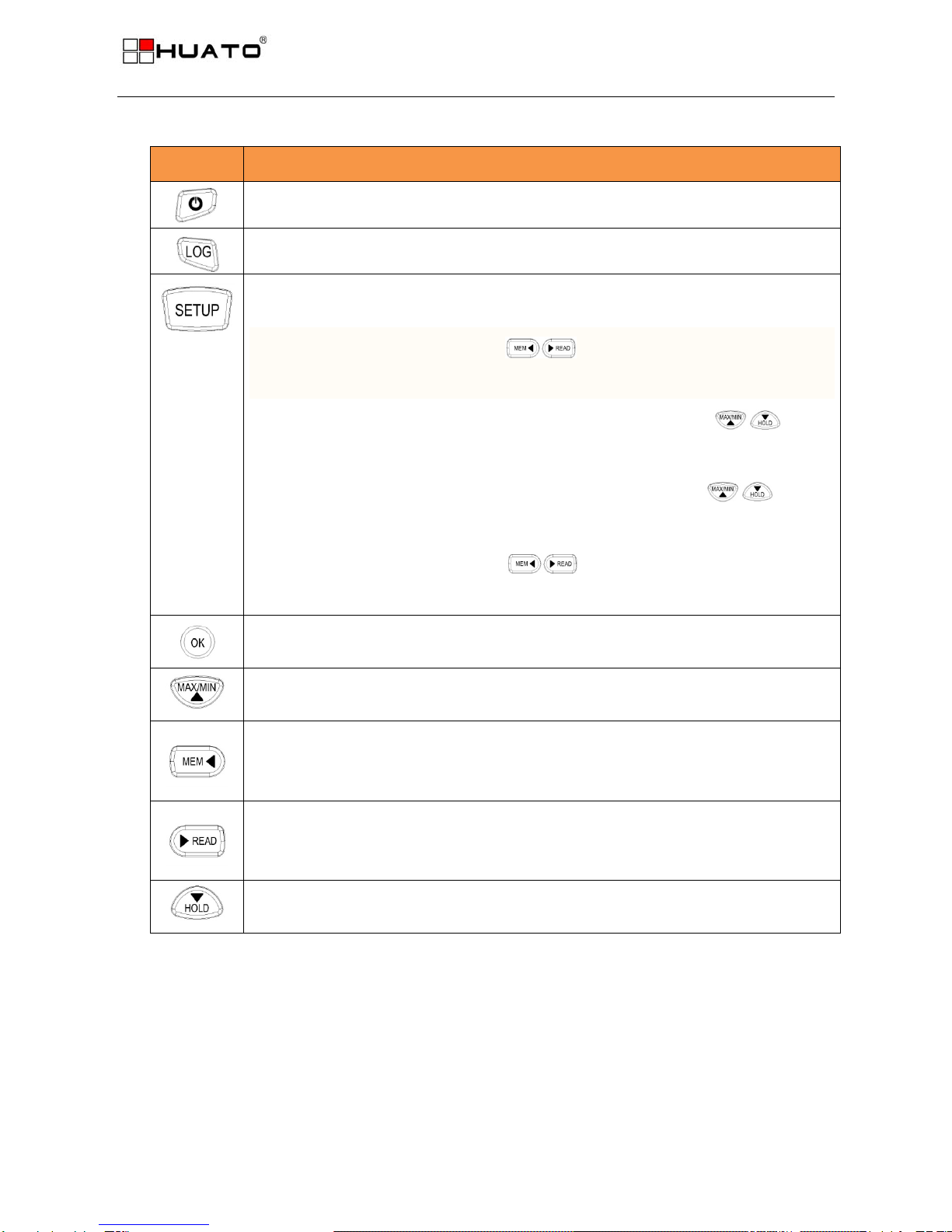
5. Unplug the cable from the logger, and then the logger is in Standby mode. Press button LOG on the
logger, then LOG displays on the screen and the logger begins to record.
6. Press LOG/STD for about five seconds, the logger will be power on (LOG mode) or off (OFF mode).
Note: The logger has three modes:
1. LOG: In the mode, the logger samples and records data timely.
2. Standby: In the mode, the logger stops to sample and record, but the LCD display is on.
3. OFF: In the mode, the logger stops to sample and record, and the LCD display is off. Tespro cannot
connect to the logger also.
2.2 Connecting the Thermometer Data Logger to PC
To connect the thermometer data logger to the computer, follow these steps:
1. Connect the USB cable to the logger and to a free USB port on the computer.
2. If you are connecting the logger to the PC for the first time, the logger will automatically be recognized
and installed on the computer.
3. Start Tespro software.
4. Click the button from the toolbar, then Tespro connects to the logger.
If more than one logger is connected to your computer at the same time, the program will ask you to
choose COM port manually.
Note: The windows operating system can not handle USB devices being unplugged and plugged back
too fast. When unplugging the logger, wait for about 5 seconds before plugging it in again. If you unplug
and plug back a device too quickly, the computer may stop recognizing any USB devices on that port. If
this happens you will have to restart the computer. This is a windows USB problem and is not related to
Tespro.

INSTRUCTIONS FOR SOFTWARE OPERATION
---------P8--------
2.3 Setup the attributes of the thermometer data logger
To setup the attributes of the thermometer data logger according to different requirements before the
normal working, click the button on the toolbar, or select Setup from the menu.
z: Get current setup information from the thermometer data logger. Click this button, and then the
old setup information is shown below.
z: Synchronize the new setup information to the logger. After changing the configuration, do not
forget clicking this button to make sure that the new configuration is wrote to the logger. The PC time
will be synchronized to the logger as well.
zName: Gives a name to the logger.
zSN: Every logger has a SN with 10 characters. The length must be 10.
zSampling Interval: The interval of sampling.
zLOG Intervals(s): The interval of recording.
zLogs Count: The count of the logs that the logger has recorded.
zMANU Count: The records in the memory. The maximum capacity is 88 readings. It will be recorded
when manually press the “MEM” button.
zCapacity: The total capacity of the logger storage. One reading includes time and three channels’
data.
zCalibrate the logger: The logger is factory calibrated to an accuracy given in the device
specifications. However, there may be times when you wish to adjust the calibration of your logger.
Tespro provides you with the ability to perform a single point offset calibration. This calibration can be
used to increase the accuracy of the logger for a restricted data range.

INSTRUCTIONS FOR SOFTWARE OPERATION
---------P9--------
2.4 Download data from the thermometer data logger.
To get the recorded logs from the logger, connect the logger to your computer and click the
button on the toolbar. Once the data is transferred from the logger to the PC, the data graph and data
listing windows will be displayed.
The graph display will be blank if there are not any logs.
Note: Push left mouse button down, and then move to select a rectangle area, when the left mouse
button is up, the graph will be redraw with the data in the selected rectangle area. Click right
button, then the graph will be redrawing with all the data in the logs file.
2.5 Delete all the logs from the thermometer data logger.
To erase all data from the logger, connect to the logger, and then click button on the toolbar.

INSTRUCTIONS FOR SOFTWARE OPERATION
---------P10--------
2.6 Data Listing Window
Click button on the toolbar, and then the data listing window is shown below.
The data pane lists the data samples collected by the logging device.
The column width of each column is adjustable by using the left mouse button and dragging the column
the desired width.

INSTRUCTIONS FOR SOFTWARE OPERATION
---------P11--------
2.7 Exporting logs from thermometer data logger
You can use Tespro to export sample data to a text file or to a Microsoft Excel file or BMP file.
z: Export sample data to an Excel file.
z: Export sample data to a text file.
z: Export graph to a BMP file.
2.8 File List
The file list pane lists all the files in the directory Logfiles which is located in the installed directory of
Tespro.
zDouble click left mouse button, then the selected file is opened.
zClick right mouse button, a popup menu is shown as below, you can rename or delete or log file.
This manual suits for next models
1
Table of contents
Other Huato Thermometer manuals