Huawei ETS2000 Series User manual

1
Tableof Contents
ThedescriptionofMaintenanceManual..................................................................................................2
Introduction.............................................................................................................................2
The purpose...........................................................................................................................2
Chapter1 FWTPrinciples andParameters................................................................................................3
1.1CircuitMakeup and Principle.............................................................................................3
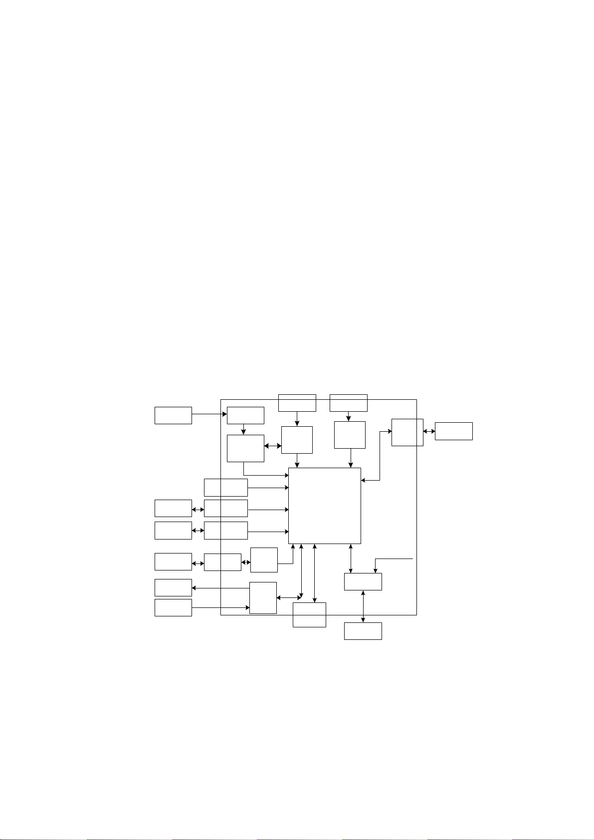
1.2Hardwarestructureofthe FWTMin-BoardFunctionalModules.........................................4
1.2.1TCPUBoardHardwareStructure.......................................................................................4
1.2.2PIPUBoardHardwareStructure.........................................................................................5
1.3Detailed Description of the FWTMain-BoardFunctionalModule........................................6
1.3.1SubscriberInterface Sub-system.........................................................................................6
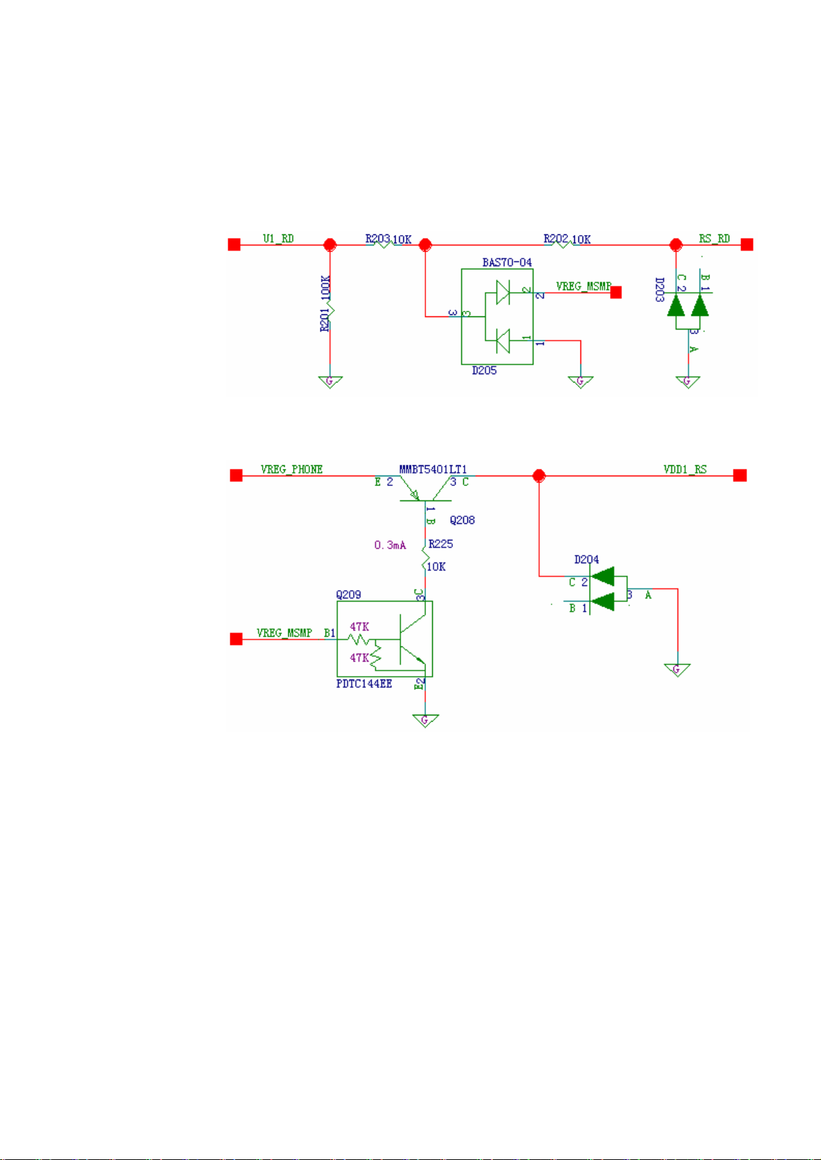
1.3.2PowerSupplyandPowerManagementSub-System.........................................................14
1.3.3MSM6000 Sub-System....................................................................................................21
1.4ParameterIndices...........................................................................................................25
1.4.1Performance Indices.........................................................................................................25
1.4.2ElectricIndices................................................................................................................26
Chapter2 Installing/UninstallingFWT....................................................................................................27
2.1InstallingFWT.................................................................................................................28
2.2UninstallingFWT.............................................................................................................30
Chapter3 ETSMaintenanceSoftware.....................................................................................................31
3.1Overview.........................................................................................................................31
3.2Operation Guide..............................................................................................................31
3.2.1HardwareConnection.......................................................................................................31
3.2.2System Configuration......................................................................................................31
3.2.3SoftwareUpgrade............................................................................................................33
Chapter4 Maintenance Procedures andSolutions toCommon Faults....................................................35
4.1MaintenanceProcedure..................................................................................................35
4.1.1TroubleshootingProcedureof theBasebandProcessingInterface Module.........................35
4.1.2RFProcessingModuleFaultMaintenance Procedure........................................................41
4.2Solution toCommon Faults:............................................................................................43
Appendix.................................................................................................................................................47
5.1 damageablesparepartlist.........................................................................................47
5.2keypad command list......................................................................................................48

2
The descriptionofMaintenance Manual
Introduction
Thismanualisprovidedasthereference materialforHuaweiauthorizedservicecenterCDMAFWT
repairingengineers. Therearefourchapters inthismanual. Thefirstchapterintroduces FWTPrinciples
and Parameters. Inthischapter,thedetail descriptionismadeforeachfunctionalmoduleofFWT.The
second chapterexplainshowtoinstall/uninstall theFWTcorrectly.Thisisthebaseofrepairingwork.
Thethirdchapterintroducesthemaintenanceprocedureand common faults. Theforthchaptershows
thedamageablesparepartlist.
Thepurpose
Afterreadingthismanual,thereadershouldbeabletomastertheknowledgeofFWThardware
componentstructure,basicworkingprinciple.Moreover,thereadershouldbeabletojudgemost
reasonsoffaults, andchangethefaultymoduleorcomponenteffectively.

Chapter1 FWTPrinciplesand Parameters
1.1CircuitMakeupandPrinciple
Keyboard&LCD
MIC
Speaker
UART
Power
Circuit
Core
Processor
Power
Circuit
RX
TX
Duplex
SRAM FLASH
BoardPIPU BoardTCPU
Figure1-1 HardwarestructureofETS2000 series FWTs
ThehardwaresystemofHUAWEIETS2000 serieswireless FWTsiscomposedof
twoboardsandperipheralslikekeypad/LCD.ThetwoboardsareFWTcentral
processingunit(TCPUboard)and interface processing unit(PIPUboard).The
hardwarestructureofthewireless FWTis showninFigure1-1.
TheTCPUboardisthecoreunit oftheFWT.ItincludesTransceiverUnitofthe
radiofrequency,centralprocessing unit,andon-boardpowergeneratorand
monitor.
ThePIPUandtheTCPUareconnectedviathe72 PINpad(72 padsarelocatedat
fourframesoftheTCPU.Theyareweldedontheinterfaceboardinthecastellation
form).ThePIPUfunctions toconverttheexternalpowerintothepowerneededby
thesystem,managethecharging/dischargingofthebattery,andprocess voice
signals. Also,itactsasaconnectingbridgebetweentheTCPUandkeypadand
LCD.

4
1.2HardwarestructureoftheFWTMin-BoardFunctional
Modules
ThehardwaresystemoftheFWTsiscomposedoftwoboardsandperipheralslike
keypad/LCD.ThetwoboardsareFWTcentralprocessingunit (TCPUboard)and
interface processingunit (PIPUboard).Keypadand LCDbelongtopurchased
equipmentoftheFWT.Thefunctionalmodulesaredividedintousersub-system,
powersub-system,MSM6000 sub-system,andradio-frequencysub-system.Each
boardhasitsownfunctionalmodules.TheTCPUboardcanbedividedbyfunction
intoMSM6000 sub-system,powerandpower-managementmodule,
radio-frequencysub-system,andPIPUboardinterface module.ThePIPUcanbe
dividedby functionintousersub-system(serialportconversionandprotection
module,R_UIMcardinterface,audiofrequencychannels1and 2, environmental
variablemonitoringmodule,PCB versionNo.detection module,etc.)andpower
and power-managementmodule(Primarypowerinterface protectionmodule,
primarypowerdetectionmodule,batterycharging/dischargingmodule,DC/DC
powermodule, and startup/shutdowncontrolmodule).
1.2.1TCPUBoardHardware Structure
TCPU
72 PIN PAD
MSM6000/
ARM
UART1
LCD
R-UIM
VCC/GND
EAR/MIC
KEYSENSE
ADC/GPIO
Power SRAM FLASH
RX
TX
Duplex
GPIO
DATA/ADDRES
Figure1-2 TCPUboardstructure
TheTCPUboardcanbedividedinto4parts, asshowninFigure1-2:MSM6000
sub-system,powerand power-managementmodule,radiofrequencysub-system,
and PIPUboardinterface module.
TheMSM6000 sub-systemcontains voicecoding/decodingunit,basebandsignal
processingunit,and theCPUsystemthroughwhichprotocolsoftwareruns. All of
thesefunctionalunitsareintegratedintheMSM6000 chip.Themainfunctionof

5
thevoice coding/decodingunitistoconductcompressingandcodingoperations
over64KvoiceanddigitalcodetrafficslikeEVRC codes, toletthembesuitable
forbeingtransmittedinwireless environment.Thebaseband signalprocessingunit
mainlyincludesfunctionslikebasebandmodulation/demodulationandchannel
coding/decoding.ItalsoincludestheCPUsystemthroughwhichprotocolsoftware
runs, as well as FLASHforstoringsoftwareandSRAM forrunning software.
Thepowerand power-managementmodulesfulfilsfunctionslikesystempower
supplyandpowermanagement.
Theradiofrequencysub-systemincludesradiofrequencyprocessingunit and
antennafeedersystem.Radiofrequencysignalprocessingfunctions cover
functionsofmodulatinganddemodulatingbasebandsignals, poweramplifying,
and frequencymodifying.Theprimaryfunctionistoconvertbasebandsignalsinto
radiofrequencysignalsproperforwireless transmissionand thereversefunction.
Thecorrespondingproperinterface is theUminterface ofCDMA2000 1x.
PIPUboardinterface modulemainlyprovidespower,PCMinterface,UART
interface, USB interface andR-UIM interface. Itis a72PIN pad
1.2.2PIPUBoardHardwareStructure
Keypad
Hook
4-wireinterface
R-UIMinterface
primary powerprotection module
powerswitch
second-time
powerswitchover
startup/
shutdown
control
serialport
protection antenna
interface antenna
LCDmodule LCD BUS
handle
speaker
microphone
audio
channel1
audio
channel2
charging circuit
battery
72PinTCPUmodulepad
second-timepower
second-time power
LCD interface
KPADinterface
charging control
DB9
Figure1-3 PIPUboardhardwarestructure
AshowninFigure1-3, thePIPUboardmainlyincludesthefollowingcircuit
modules, usersub-system,powersupplyandpowermanagementmodule.
Theusersub-systemincludesserialportprotectionmodule,R_UIMcardinterface,
audiochannels 1 and2, environmentalvariablemonitoringmodule, etc.

6
Theserialportprotectionmoduleismainlytofulfillthefunctionofserial-port
ESDprotection.
TheR_UIMcardinterfacecircuit ismainlytocontributetothecommunication
betweenCPUandR_UIMcardandprovideandprotectthepowerfortheR_UIM
card.
1)Audio channel1 fulfills thefunctionofdrivingmicrophoneandreceiverinthe
telephonehandle.
2)Audiochannel2fulfillsthefunctionofdrivinghands-free microphoneand
speaker.Thespeakerhas ringingfunction.
3)Theenvironmentalvariablemonitoringmodulefulfillsthebatterytemperature
sampling function.
4)Thepowerand powermanagementmodulecontainsprimarypowerinterface
protection module,batterycharging/dischargingmodule,DC/DCpowermodule,
and startup/shutdowncontrolmodule.
5)Theprimarypowerinterfaceprotectionmodulefulfills theantistaticfunction.
6)Thebatterycharging/dischargingmodulefulfillschargingmanagement
functionforthebattery.
7)TheDC/DCpowermodulefulfillssecond-timeDCpowerconversionwithin
theboard,andprovidesfunctionslikevoltagestabilizing,and constantcurrentto
cooperatewiththecharging/dischargingcircuit.
8)Thestartup/shutdowncontrolmodulefulfillsstartup/shutdowncontrol
functionoftheexternaltouchingswitchandcontrolfunctionofprimarypower
startup andsoftwareshutdown.
Besidestheabovemodules, thefollowinginterfacecomponentsarealsoincluded:
ConnectingpadbetweenPIPUboardandTCPUboard, DB9 connectoroftheserial
port,lineforconnecting theLCDmodule,lineforconnectingKPAD,4-linecrystal
headerforconnectingthehandle, andinsertingspringand slideswitch.
1.3DetailedDescriptionoftheFWTMain-Board
Functional Module
1.3.1Subscriber InterfaceSub-system
1. Asynchronous SerialPortDriveCircuit
Weputthedriveoftheserialportontotheserialportline.Theoutputpowerlevel
oftheserialportdrivedoesnotmatchtheMSM6000 powerlevel---Thehigh
powerlevelofMSM6000 is2.8V,whilethehighpower leveloftheserialport
driveis4.4V.Thus, whatisneededistomakeapower-levelconversionand
protectioncircuitforthetransistortoconvertthepower leveloftheserialport

7
circuit.Thedualtransientsuppressiondiodeprotectstheserialportandprevents
thedamagetowards thesystemfromabnormalpowerlevelinputsuchas ESD.
Serialportsignals aredividedinto5 groups:
1) DatareceivingsignalRS_RD(Input);Datasending signalRS_TD
(Output).
2) Trafficsignalclearing/sendingRS_CTS(Input);Requestsending
RS_RTS(Output)
3) Modemstatussignal(modemreferstoFWT);Carrierwavedetection
UART1_DCD(Output);DataterminalreadyUART1_DRT(Output)
4) SerialportindicatingUART1_IND (Output).Thepowerlevel(high/low)
isdeterminedbytheserialportline.Thepowerleveldifferentiates
debuggingdatalineandhigh-speeddataline.Lowpowerlevelindicates
high-speed(230400BPS)andhigh powerlevelindicateslowspeed
(115200BPS).
5) ExternalserialportdrivepowersupplyVDD1_RS.Thepowerswitchis
controlledbytheMSM_Pvoltage.
Thecircuits areshownbythefollowingdiagrams:
Inputpowerlevelconversion circuit:
Figure1-4 Inputpowerlevelconversion circuit
Outputpowerlevelconversioncircuit:

8
Figure1-5 Outputpowerlevelconversioncircuit
Datareceivingsignalpowerlevelconversioncircuit.Thepowerlevelconversion
ofsignalUART1_RXisaccomplishedbyclampcircuit.Thereasonliesinthatthe
signalpower-levelneedstobeloweredtodetectwhetherornottheserialportline
is connectedwhenthereareno datalines.
Figure1-6 Datareceivingsignalpowerlevelconversioncircuit
VDD1_RS powersupplycircuit:
Figure1-7 VDD1_RS powersupplycircuit
Thecircuit mayhavethefault thattheserialportisNOTthrough.Thenyoucan
connecttheserialportlineinthestartup statustocheckwhetherornotthe
VDD1_RS voltageiswithintherangefrom3to4.4V.Ifit isnot,checkQ209 and
Q208.
2Audiointerface
TheETS2000 seriesFWTaudiointerfacesincludehandleinterface (microphone
and earphoneareincluded),speakerinterface andhands-free microphoneinterface.
Since thepowerofthespeakerisquitehigh,anaudioamplifierisadoptedandthe
MICinterfaceandthehandleinterface aredirectlyconnected.
Figure1-8showsthecircuitofthehandlemicrophoneinterface.Beadand
capacitorconstitutethe -typefiltercircuit.

9
Figure1-8 Handlemicrophoneinterface
Figure1-9showsthecircuit ofthehandlereceiverinterface.Beadandcapacitor
constitutetheL-typefiltercircuit.
Figure1-9 Handlereceiverinterface
Possiblefault ofthehandlechannel: Ifthehandlehasproblemsinsendingand
receivingsignals, checkwhetherornotthecircuitisbrokenatL103, L101, L105,
and L106
Thehands-freeinterface circuit isshowninFigure 1-10. Themicrophoneinterface
MIC2_Pdirectlyconnectsthemicrophone.TheEAR2signalamplifiesthedrive
speakerviatheaudiopoweramplification.Theswitchofthespeakeriscontrolled
bythebiasvoltageofMIC2_P.Whenthevoicechannelisclosed,thebiasvoltage
ofMIC2is0, andtheaudioamplificationfunctionisclosedtoenterthepower
sparingstatus.

10
Figure1-10 Hands-free interface circuit
Possiblefaultsofthehands-freechannel:Thereisnoringing.Thencheckwhether
ornotU101 is damaged.
3LCDunit
IntheETS2000 seriesFWTs, LCDisaperipheralcomponent.Ifit isbroken,it can
bereplaceddirectly.Thenyouhadbetterbeclear aboutthefunctionofLCDto
chooseproperLCDcodes. If thedotmatrixhasnobackfacet,choose23040026.
If thedotmatrix hasolivinebackfacet, choose23040028.
LCD(Here,wetakesdotmatrixLCDastheexample)connectsthesystemvia2
10PINconductorlayouts. Interfaces areshowninTable1-1.
See Figure1-11 forhardwareinterfaces:

11
Figure1-11 LCDHardwareinterfaces
figure1-18System LCD interfaces
Serial
No. Signal
name Direction
Signalfunctiondescription Remarks
1LCD_AOLED backfacet(+)
2LCD_KOLED backfacet(-)
3VSS -- Ground
4VDD -- Power: (2.84V)
5RS O
High TheBUS isindata
transmissionstatus L:
Commandstatus
6R/WORead/writesignal.
7EOEnablingsignal
8CS1Ochipselectionsignal(IC1)
9NA Reservedpin
10 D0O8-BitBUSbit
11 VSS -- Ground
12~14 D1~D3O8-Bit BUSbit
15 VSS OGround
16~19 D0~D7O8-Bit BUSbit
20 VSS -- Ground
3. Keypadunit
IntheETS2000 seriesFWTs, thekeypadisaperipheralcomponent.Ifit isbroken,
it canbedirectlyreplaced.Thennotetheusethecorrectversionofthestructure
suite.Theinterface betweenthesystemandthekeypadis shownbyTable1-1.
Presentedbelowis thecircuit principle:

12
Figure1-12 Keypadhardwareinterface
Thekeypadstatusindicatorand thebackfacetareshowninthediagrambelow.
Theindicatoruses theQ102 drive. See Figure1-13.
Figure1-13 Keypadhardwarestatus indicatorandbackfacetinterface

13
figure1-18System keypad interfaces
Serial
No. Signalname Direction Signalfunctiondescription Remarks
1KEY_BACKLIGHT
O
Keypad back-facet drive.
Currentsourceoutput.
0--150mA.
2STATUS_AI Communicationindicator
connectingtheLED (-) end
3VREG_PHONE O Power supplyconnectingthe
LED (+) end
4VSS IO Keypad grounding
5NA
6KPAD_ROW3IKeypad rowscanningsignal3
7KPAD_ROW2IKeypad row scanning signal2
8KPAD_ROW1IKeypad row scanning signal1
9KPAD_ROW0IKeypad row scanning signal0
10 VSS IO Keypad grounding
11 VSS IO Keypad grounding
12 KPAD_COL5 O Keypad columnscanning
signal5
13 KPAD_COL4 O Keypad columnscanning
signal4
14 KPAD_COL3 O Keypad columnscanning
signal3
15 KPAD_COL2 O Keypad columnscanning
signal2
16 KPAD_COL1 O Keypad columnscanning
signal1
17 KPAD_COL0 O Keypad columnscanning
signal0
18 VSS IO Keypad grounding
19 SPEAKER_POHands-free speaker signalP
20 SPEAKER_NOHands-free speaker signalN
4. R_UIM cardinterface circuit
TheprimaryfunctionoftheR_UIMcardinterfacemoduleistoprovidethe
R_UIMcardconnectorandconductESDprotectiontowardssignals. The
connectingmodeis showninTable1-3.

14
figure1-18R_UIMcardinterfacemodulesignals
Signal Sourceor target module
Function
VREG_PHONE Inter-boardinterface
module
UIMcardpower supply
RUIM_RSTInter-boardinterface
module
UIMcardresetting signal
RUIM_CLKInter-boardinterface
module
UIMcardclocksignal
RUIM_DATInter-boardinterface
module
UIMbi-directionaldatasignal
RUIM_EN Inter-boardinterface
module
UIMenablingsignal
VDD_ SIMofETS2000 seriesFWTispoweredbythepowermanagementchip on
theTCPC board. R-UIM_ENdirectlyprovidespowerfortheUIM card.SeeFigure
1-14.
Figure1-14 ETS2000 series FWTVDD_SIMpowersupply
1.3.2Power Supplyand Power Management Sub-System
1. DC/DC powerModule
Theexternalpowerovervoltageprotectionmoduleprotectstheinputpower. When
theinputvoltageexceeds30V,theprotectioncircuit will function.Thenthesilicon
controlledthyristorisinthecontinuitystatusandtheself-healingfuseF301 will be
blown.Thus, thepowerprotectioncircuit will becut(Thefunctionisonlytobe
fulfilledontheIndianBSNLFWT).Thecircuit is showninFigure1-16.

15
Figure1-15 Externalpowerovervoltageprotectionmodule
2. DC/DC powermodule
TheDC/DCpowermodulegenerates4.4Vmainpowernecessaryfortheoperation
ofthewholemachine.Italsofulfillstheconstantcurrentchargingfunction.The
maximumoutputcurrentis830mA.WemainlyusethePWMcontrolchip(U302)
andtheswitchtransistor(Q301)tocompletethesecond-timeswitchpowercircuit.
Itis theswitchpowersupplythatconverts theexternalpowerinto4.4V.
See Figure1-17

16
Figure1-16 Powertransfercircuit
ThePWMcontrolchipadoptsTL494, including2differentialamplifiers, 1
externaladjustableoscillator,1pulsecomparer,1timeoverflowcontroller,and1
outputcontrolcircuit.
ThedifferentialamplifiercanworkwithintherangefromAC-0.2Vto0.2V.The
timeoverflowcontrollerhasafixedoffsettoassurethestableoutputincaseofthe
changedexternalinput.Theexternaloscillatingcircuit canbesetthroughRt/Ct
(Theworkingfrequencytobesetis100KHZ).Thefollowingblockdiagram
illustrates thefunctionsofTL494:

17
Figure1-17 TL494
3. Powersupplyanti-reverse-insertion circuit and externalinterface
D305 and D301 fulfilltheanti-reverse=insertionfunctionoftheexternalpower
supply.EXT_DCsignal: Whetherornottheexternalpowersupplyexists;
V_BATTsignal: Batteryvoltage;VREG_PHONEsignal: Voltageofthe
second-timepowersupply.
Figure1-18 Anti-reverse-insertioncircuit

18
4. Batterycharging/dischargingmanagement
Here,thecontroloverbatterychargingisaccomplishedbycontrollingtheoutput
currentofthesecond-timepowersupply.Whenthebatteryisinfastcharging
status, thegridofQ303 islowandisnotthrough andtheinternaldifferential
amplifierof494 willcontrolthepulsedutyratioofPWM, sothattheoutput
currentoftheswitchpowersupplywill berestrictedto830mA. Whenthebatteryis
inslowchargingstatus, thegridofQ303 ishighandthrough,andtheinternal
differentialamplifierof494 will controlthepulsedutyratioofPWN,sothatthe
outputcurrentoftheswitchpowersupplywillberestrictedto75mA.Finally,the
fastchargingoperationwillbestoppedandreplacedbyslowchargingoperation.
Thefeedbackloopisaccomplishedbyoperationalamplifier1ofTL494. See
Figure1-20 forthecircuit. .
Figure1-19 Chargingcircuit
Becausethebatteryonthecircuit isdirectlyconnectedwith4.4Voutputofthe
second-timepowersupply,whentheexternalpowersupplyisnotconnected,the
batterydirectlyusessignalVREG_PHONEtosupplypowerforthesystem.Here,
thereis noaspecialdischargingcontrolcircuit.
5. Second-timepowervoltage-limitingmodule
Thesecond-timepowervoltage-limitingmodulelimitsthesecond-timepower
voltageto4.4V.whentheconstantcurrentchargingoperationisended,the
second-timepoweroutputisstabilizedto4.4Vtoprovidepowerfortheback-level
circuit.. Thefeedbackloopisaccomplishedby operationalamplifier2ofTL494.
See thefollowingfigureforthecircuit.

19
Figure1-20 Second-timepowervoltage-limitingmodule
6. Short circuit protection and overvoltageprotectionmodule
Q302, Q320, Q321,and D381 constitutetheshortcircuit protectionand
overvoltageprotectionmodule.Ifshortcircuit happenstoVREG_PHONE, Q321
will bethroughtotriggeracircuit constitutedbyQ302 andQ320. Asaresult,the
DTvoltageofU302 will beimprovedto5V, theU302 switchoutputwill beclosed,
and Q301 willbeprotected.Ifavoltagefeedbackloopfault causestheoutput
voltagetobeimproved,D381 will bethroughtotrigger acircuit constitutedby
Q302 and Q320. ThentheDTvoltageofU302 will beimprovedto5V,theU302
switchoutput,andthepowersupplywill beclosed.Asaresult,thehighvoltage
will bepreventedfromblowingthebacklevelcircuit.See Figure1-22 forthe
circuit.

20
Figure1-21 Shortcircuit protectionandovervoltageprotectionmodule
7. Startup/shutdownmodule
S301 fulfillstheswitchfunction.TurntheswitchtotheON side,thenTERM_ON:
Lowelectricitylevelstartuppulse;SWITCH_ON:High electricitylevelstartup
indicatingsignal. See Figure1-23 forthecircuit.
Table of contents
Other Huawei Telephone manuals

Huawei
Huawei F617 User manual

Huawei
Huawei F616 User manual

Huawei
Huawei F201 User manual

Huawei
Huawei Mate20 Pro User manual

Huawei
Huawei MC850 User manual

Huawei
Huawei P9 EVA-L09 User manual

Huawei
Huawei F688 User manual

Huawei
Huawei ETS3125i User manual

Huawei
Huawei F615 User manual

Huawei
Huawei F615-51 User manual

Huawei
Huawei G Play mini CHC-U23 User manual

Huawei
Huawei ETS2058 User manual

Huawei
Huawei F385 User manual

Huawei
Huawei ETS2022+ User manual

Huawei
Huawei F203 Instruction Manual

Huawei
Huawei Nova 7i User manual

Huawei
Huawei ETS2252+ User manual

Huawei
Huawei F615 User manual

Huawei
Huawei F610 User manual

Huawei
Huawei ETS3125i User manual