Pub. 42004-304A
GAI-Tronics Corporation P.O. Box 1060, Reading, PA 19607-1060 USA
610-777-1374 n800-492-1212 nFax: 610-775-6540
VISIT WWW.GAI-TRONICS.COM FOR PRODUCT LITERATURE AND MANUALS
GAI-TRONICS® CORPORATION
A HUBBELL COMPANY
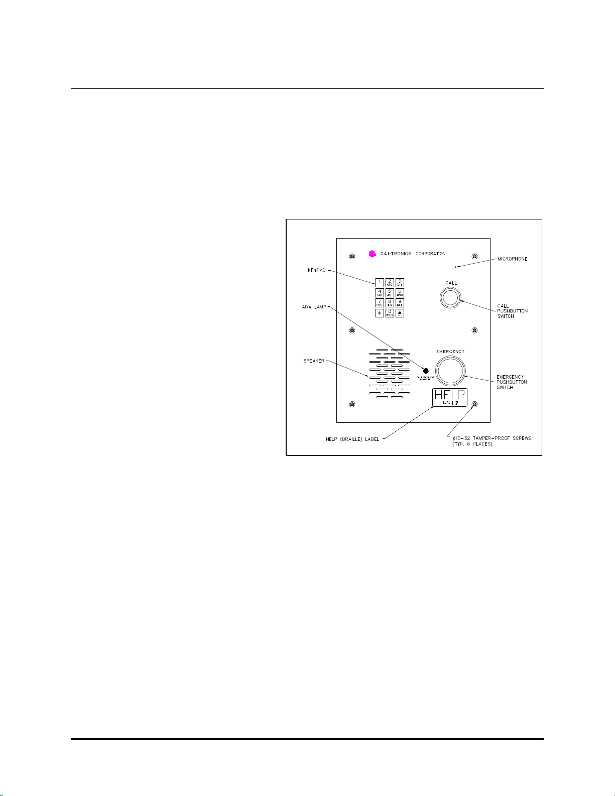
Model 298 ADA-Compliant
Emergency Telephone
Table of Contents
Confidentiality Notice.............................................................................................................................3
Introduction............................................................................................................................................3
Operation ...............................................................................................................................................3
Installation..............................................................................................................................................4
SAFETY GUIDELINES.................................................................................................................................... 4
INSTALLATION GUIDELINES....................................................................................................................... 4
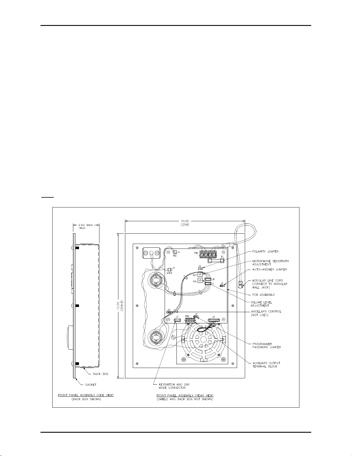
MOUNTING AND WIRING INSTRUCTIONS................................................................................................. 4
Hardware Configuration........................................................................................................................6
Auto-answer Configuration............................................................................................................................ 6
Polarity Configuration .................................................................................................................................. 7
Programming Password Configuration.......................................................................................................... 7
MICROPHONE SENSITIVITY AND SPEAKER VOLUME ADJUSTMENT................................................... 8
Programming Instructions .....................................................................................................................8
REMOTE PROGRAMMING............................................................................................................................. 8
Password Enabled Programming................................................................................................................... 8
Password Disabled Programming.................................................................................................................. 9
LOCAL PROGRAMMING................................................................................................................................ 9
Programming Sequences......................................................................................................................10
PROGRAMMING DIALING OPERATION.................................................................................................... 10
Auto-dialing................................................................................................................................................ 10
Outside Line Auto-dialing ........................................................................................................................... 11
Ring-down Operation .................................................................................................................................. 13
PROGRAMMING PASSWORD OPERATION ............................................................................................... 14
PROGRAMMING DISCONNECT OPERATION............................................................................................ 14
PROGRAMMING THE SILENT MONITORING FEATURE.......................................................................... 16
NEW/OLD DTMF TRANSMITTER SELECTION.......................................................................................... 16
AMERICANS WITH DISABILITIES ACT (ADA) PROGRAMMING............................................................ 16
Call Received Indicator Lamp Activation.................................................................................................... 16
Location Identification Code Dialing .......................................................................................................... 17
DTMF Call Disconnect ............................................................................................................................... 17