manuals.online logo
Brands
  1. Home
  2. •
  3. Brands
  4. •
  5. HUBBELL LIGHTING
  6. •
  7. Work Light
  8. •
  9. HUBBELL LIGHTING DUAL-LITE SPECTRON SEWL Series Owner's manual

HUBBELL LIGHTING DUAL-LITE SPECTRON SEWL Series Owner's manual

Wet Location/NEMA 4X Die-Cast Aluminum LED Exit Sign
Installation, Operation and Maintainance Instructions
SEWL Series
Hubbell Lighting, Inc. Life Safety Products • www.dual-lite.com
Copyright© Hubbell Lighting, Inc., All Rights Reserved • Specications subject to change without notice. • Printed in U.S.A. [EC 090204002] 93022482 A 9/09
Self-Testing/Self-Diagnostic EmergencyModels
All models ordered with the Dual-Lite Spectron
self-testing/self-diagnostic electronics system provide:
■Visual indication of AC power status
■Visual indication of all self-diagnostic test cycles
■Visual indication of unit malfunctions including:
■Battery fault
■Charger fault
■Transfer Fault
■Lamp fault
Bi-Color LED Status Indicator
Self-testing/self-diagnostic units are provided with a
single, bi-color LED which serves as a combination AC
power, self-test and service alert status indicator. During
normal operation, the green status LED will be constantly
illuminated, indicating the presence of AC power. During
all automatic or manual self-test cycles, the green Status
LED will blink at a one cycle per second rate indicating
“Test In Progress". If a fault condition is detected during
any automatic or manual self-test cycle, upon completion
of test, the red status indicator will provide a “service alert
code” – see table below.
Service Alert Code Description
One blink ON/pause Battery not connected
Two blinks ON/pause Battery fault
Three blinks ON/pause Charger fault
Four blinks ON/pause Transfer circuit fault
Five blinks ON/pause Lamp failure
Manual Test
Using the unit test switch, users can initiate different
duration test cycles based on the following table:
To Initiate Action: Test Cycle
Press switch once 1 minute
Press switch twice 90 minute
Pressing test switch at any time after a test cycle has
begun cancels the remainder of test and returns the unit
to normal operation. (NOTE: Batteries are often shipped
in a discharged state – this is normal – battery requires
charging. Allow several hours of charge before testing
unit.)
Spectron units also provide:
Brownout protection – unit transfer to emergency mode
with low AC input voltage.
Time Delay Re-transfer – unit will remain in emergency
mode for additional time after AC power is restored.
EMERGENCY MODEL
TROUBLESHOOTING
AC-On Light does not illuminate
• Check AC wiring connections
Emergency LEDs do not work
• Battery is shipped disconnected. Connect leads from
battery to charger PCB and charge before testing.
• Make sure connections to LED board are properly
seated.
• Check wiring connections.
Maintenance
Exit signs should be tested and maintained in accordance
with National Electrical Code and NFPA 101 Life Safety
Code requirements. It is recommended that exit signs be
tested for a minimum of 30 seconds once a month and 90
minutes once a year.
The automatic monthly tests of the Spectron units satisfy
this requirement. The required annual test can be initiated
manually with the test switch, as required by the safety
code.
RECYCLING INFORMATION
All aluminum components are recyclable.
All cartons contain recycled materials.
Please recycle.
NOTICE:
Emergency exit signs contain rechargeable batteries
which must be recycled or disposed of properly.
Use CAUTION when handling batteries.
LED REPLACEMENT
(Contact factory)
IMPORTANT SAFEGUARDS
When using electrical equipment, basic safety precautions should always be followed including the following.
READ AND FOLLOW ALL SAFETY
INSTRUCTIONS
1. Do not let power supply cords touch hot surfaces.
2. Do not mount near gas or electric heaters.
3. Equipment should be mounted in locations and at heights where it will not readily be subject to tampering by
unauthorized personnel.
4. The use of accessory equipment not authorized by the manufacturer may cause an unsafe condition.
5. Do not use this equipment for other than its intended purpose.
6. Service of this equipment should be performed by qualied service personnel.
INSTALLER:
•SEE UNIT LABEL FOR ADDITIONAL MODEL SPECIFICATIONS
•SAVE THESE INSTRUCTIONS FOR USE BY OWNER/OCCUPANT
93021636
93021638
93021640
93021641
93021643
93021644
93021645
93021646
93024663
WARNING – This product contains chemicals known to the State of California to cause cancer, birth defects and/or
other reproductive harm. Thoroughly wash hands after installing, handling, cleaning, or otherwise touching this product.
93021636
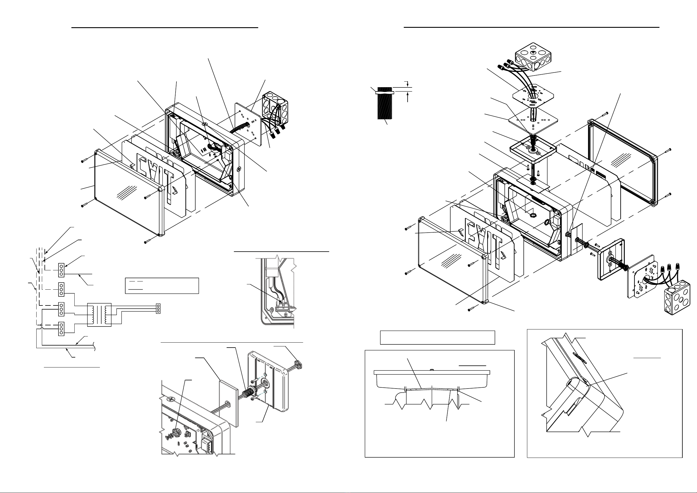
CEILING OR END MOUNT INSTALLATION
WALL MOUNT INSTALLATION
TRANSFORMER
CONNECTOR TO
LED PCB (J1)
WIRE HARNESS
FROM HEATER
ASSY 7 PIN
CONNECTOR
(WHEN PROVIDED)
TO GROUND
CONNECTION
ON FRAME
277
120
COM
TO JUNCTION
BOX
3 PIN PUSH
CONNECTOR (QTY 4)
SUPPLIED PIGTAIL LEADS
PREWIRED AT FACTORY
BLK
WHT
GREEN (GROUND)
PIGTAIL LEAD
RED
PIGTAIL LEAD
BLK
PIGTAIL LEAD
WHT
PIGTAIL LEAD
ORG
BLK
WHT
GREEN
WIRING DIAGRAM
10. REMOVE CHEVRON(S) IF REQUIRED.
DRIVE CHEVRON TOWARDS BACK
OF STENCIL BY TAPPING AROUND
THE ENTIRE PERIMITER FROM
FRONTSIDE OF STENCIL FOR CLEAN
BREAKOUT.
2. REMOVE APPROPRIATE KNOCKOUTS
FOR WALLBOX SCREWS.
4. AT TACH PRE-TINNED PIGTAIL LEADS
PROVIDED TO AC INPUT CONDUCTORS.
3. IF USING CONDUIT, REMOVE
PIPE PLUG, OTHERWISE
REMOVE CENTER KNOCKOUT.
5. REMOVE ADHESIVE BACKING FROM
MOUNTING GASKET & APPLY TO
EXIT BACKPLATE.
6. ROUTE PIGTAIL LEADS THRU CENTER
KNOCKOUT IN BACKPLATE & MOUNT
SIGN TO WALLBOX.
7. AT TACH ADHESIVE WIRING SADDLE
AND ROUTE WIRES INTO CHANNEL.
8. ROUTE PIGTAILS THRU LIGHTBOX
(SEE WIRING DIAGRAM & DETAIL 1)
AND MAKE PROPER CONNECTIONS USING
PUSH CONNECTORS.
9. WHEN PROVIDED, AT TACH 2-PIN BATTERY CONNECTOR
TO PC BOARD AS SHOWN. (SEE BATTERY CONNECTION DETAIL)
11. CONFIRM ALL WIRING IS DRESSED
PROPERLY, HANG STENCIL & DIFFUSER
ONTO FRAME PINS.
12. SEAT COVER & SECURELY TORQUE
COVER SCREWS TO 16 IN-LBS. (SEE DETAIL 2)
AC TRANSFORMER
120VAC-CONNECT BLACK & WHITE LEADS.
277VAC-CONNECT RED & WHITE LEADS.
13. REMOVE CHEVRON(S) IF
REQUIRED. DRIVE
CHEVRON TOWARDS
BACK OF STENCIL BY
TAPPING AROUND THE
ENTIRE CHEVRON
PERIMITER
FROM FRONTSIDE OF
STENCIL FOR CLEAN
BREAKOUT.
3. AT TACH PRE-TINNED PIGTAIL LEADS
PROVIDED TO AC INPUT CONDUCTORS.
2. REMOVE PIPE PLUG.
4. FEED LEADS THROUGH CENTER OF
UNIVERSAL MOUNTING PLATE AND
AT TACH PLATE TO ELECTRICAL BOX.
5. AFFIX NUT TO PIPE NIPPLE. SLIP
THROUGH CANOPY CENTER HOLE AND
AFFIX SECOND NUT ONTO PIPE NIPPLE
AND TIGHTEN. THIS WILL LOCK PIPE
NIPPLE TO CANOPY. (SEE DETAIL)
7. ROUTE PIGTAILS THRU GASKET & CANOPY.
6. REMOVE ADHESIVE BACKING FROM
MOUNTING GASKET & APPLY TO
CANOPY.
8. WITH SCREWS SUPPLIED (QTY 2) SECURE
CANOPY TO UNIVERSAL MOUNTING PLATE
9. REMOVE ADHESIVE BACKING FROM FRAME
GASKET, ROUTE PIGTAILS THROUGH GASKET
& APPLY TO CANOPY. (SEE DETAIL 1)
10. ROUTE PIGTAILS THROUGH EXIT FRAME
AND PIPE NIPPLE NUT. AFFIX NUT TO
PIPE NIPPLE AND TIGHTEN TO SECURE
EXIT FRAME. (SEE DETAIL 1)
11. ROUTE PIGTAILS TO PUSH CONNECTORS.
(SEE WIRING DIAGRAM & DETAIL 1)
12. WHEN PROVIDED, AT TACH 2-PIN BATTERY
CONNECTOR TO PC BOARD AS SHOWN.
14. CONFIRM ALL WIRING IS DRESSED PROPERLY,
HANG STENCIL/DIFFUSER ONTO FRAME PINS. 15. SEAT COVER(S) & SECURELY TORQUE
COVER(S) SCREWS TO 16 IN-LBS. (SEE DETAIL 2)
DETAIL 1
CANOPY GASKET
COMPRESSION STOPS
CANOPY
ANTI-ROTATION
RIBS
NOTE: PIPE NIPPLE NUT INSIDE EXIT FRAME SHALL BE TORQUED TO 40 IN-LBS
SO THAT CANOPY GASKET COMPRESSION STOPS SEAT AGAINST EXIT
FRAME. THIS INSURES THAT THE GASKET IS COMPRESSED PROPERLY
TO SEAL SIGN & SIGN WILL BE SECURE AGAINST ROTATING ON CANOPY.
GASKET
NOTE: CLEAR POLYCARBONATE COVER(S) ARE SIMILAR TO THE CANOPY IN THAT THEY
ALSO HAVE COMPRESSION STOPS (COVER HAS THEM AT ALL 4 CORNERS)
THAT SEAT AGAINST EXIT FRAME. THIS INSURES GASKET WILL BE
COMPRESSED PROPERLY TO SEAL SIGN.
DETAIL 2
SEAT COVER TO FRAME
CENTER KNOCKOUT
1. USE SPANNER SCREW BIT (PROVIDED)
TO REMOVE & TIGHTEN ALL SPANNER
SCREWS.
1. USE SPANNER SCREW BIT (PROVIDED)
TO REMOVE & TIGHTEN ALL SPANNER
SCREWS.
CANOPY PIPE NIPPLE
NUT
APPROX. 3/16"
NOTE: FOR END MOUNTED SINGLE FACED SIGNS, THE
BACKPLATE AND CLEAR COVER WITH STENCIL/DIFFUSER
CAN BE SWAPPED FOR MOUNTING VERSATILITY
A
IMPORTANT: TO WEATHERPROOF FOR OUTDOOR INSTALLATION,
BE SURE TO SEAL ALL OPENINGS — MOUNTING, CONDUIT, ETC.
IMPORTANT: TO WEATHERPROOF FOR OUTDOOR INSTALLATION,
BE SURE TO SEAL ALL OPENINGS — MOUNTING, CONDUIT, ETC.
TORQUE BACK PLATE
SCREWS TO 20 IN-LBS.
REQUIRED NEMA 4X RATED WALL MTG DETAIL
NUT
TORQUE TO
40 IN-LBS
1/4-IN. THICK CANOPY
BACKPLATE
GASKET
(NEMA 4X ONLY)
MOUNT POTTED PIPE NIPPLE (SHORT END)
TO CANOPY & SECURE WITH NUT SUPPLIED.
CANOPY
NUT
TORQUE TO
50 IN-LBS
93024663
FOR NEMA SEE NEMA MOUNTING DETAIL
BATTERY CONNECTION DETAIL
2-PIN BATTERY
CONNECTION
93021641
93021644
93021643 93021640
93021638
93021646
93021645

Other HUBBELL LIGHTING Work Light manuals

HUBBELL LIGHTING LCC6LED Series User manual

HUBBELL LIGHTING

HUBBELL LIGHTING LCC6LED Series User manual

HUBBELL LIGHTING DUAL LITE PGF1 LED Wallpack Manual

HUBBELL LIGHTING

HUBBELL LIGHTING DUAL LITE PGF1 LED Wallpack Manual

Popular Work Light manuals by other brands

Night Stick XPR-5572R instruction manual

Night Stick

Night Stick XPR-5572R instruction manual

Stanley FATMAX SFMCL050 Original instructions

Stanley

Stanley FATMAX SFMCL050 Original instructions

Ecco EW2530 Series Installation and operation instructions

Ecco

Ecco EW2530 Series Installation and operation instructions

Konig & Meyer Twin Head Pro Instructions for use

Konig & Meyer

Konig & Meyer Twin Head Pro Instructions for use

Dynamic Spectra dome Installation instruction

Dynamic

Dynamic Spectra dome Installation instruction

luceco LUXPACK BATTEN Installation & operating instructions

luceco

luceco LUXPACK BATTEN Installation & operating instructions

TE-Group Dymond Warm White LED strip user manual

TE-Group

TE-Group Dymond Warm White LED strip user manual

NightSearcher BeatLite 500 user manual

NightSearcher

NightSearcher BeatLite 500 user manual

Makita DML813 instruction manual

Makita

Makita DML813 instruction manual

HAZET-WERK HAZET 1979-7 instruction manual

HAZET-WERK

HAZET-WERK HAZET 1979-7 instruction manual

Makita ML003G instruction manual

Makita

Makita ML003G instruction manual

Humanscale Horizon Task Light Disassembly instructions

Humanscale

Humanscale Horizon Task Light Disassembly instructions

Commercial Electric 54569141 Use and care guide

Commercial Electric

Commercial Electric 54569141 Use and care guide

Adesso GROVER 2150-01 Assembly instructions

Adesso

Adesso GROVER 2150-01 Assembly instructions

Strend Pro BL2S20A1-E2 instruction manual

Strend Pro

Strend Pro BL2S20A1-E2 instruction manual

Generac Power Systems Magnum MLT6SC owner's manual

Generac Power Systems

Generac Power Systems Magnum MLT6SC owner's manual

Saber Compact ATD-80376 owner's manual

Saber Compact

Saber Compact ATD-80376 owner's manual

Drill Master 67032 Set up and operating instructions

Drill Master

Drill Master 67032 Set up and operating instructions

manuals.online logo
manuals.online logoBrands
  • About & Mission
  • Contact us
  • Privacy Policy
  • Terms and Conditions

Copyright 2025 Manuals.Online. All Rights Reserved.