Hubbell GAI-Tronics SmartSeries 7805-821-EX User manual

Pub. 42004-653L2B
GAI-Tronics Corporation P.O. Box 1060, Reading, PA 19607-1060 USA
610-777-1374 800-492-1212 Fax: 610-796-5954
VISIT WWW.GAI-TRONICS.COM FOR PRODUCT LITERATURE AND MANUALS
GAI-TRONICS CORPORATION
A HUBBELL COMPANY
Model 7805-821-EX SmartSeries Handset
Station with RTU for ATEX Zone 1
Confidentiality Notice
This manual is provided solely as an operational, installation, and maintenance guide and contains
sensitive business and technical information that is confidential and proprietary to GAI-Tronics. GAI-
Tronics retains all intellectual property and other rights in or to the information contained herein, and
such information may only be used in connection with the operation of your GAI-Tronics product or
system. This manual may not be disclosed in any form, in whole or in part, directly or indirectly, to any
third party.
Introduction
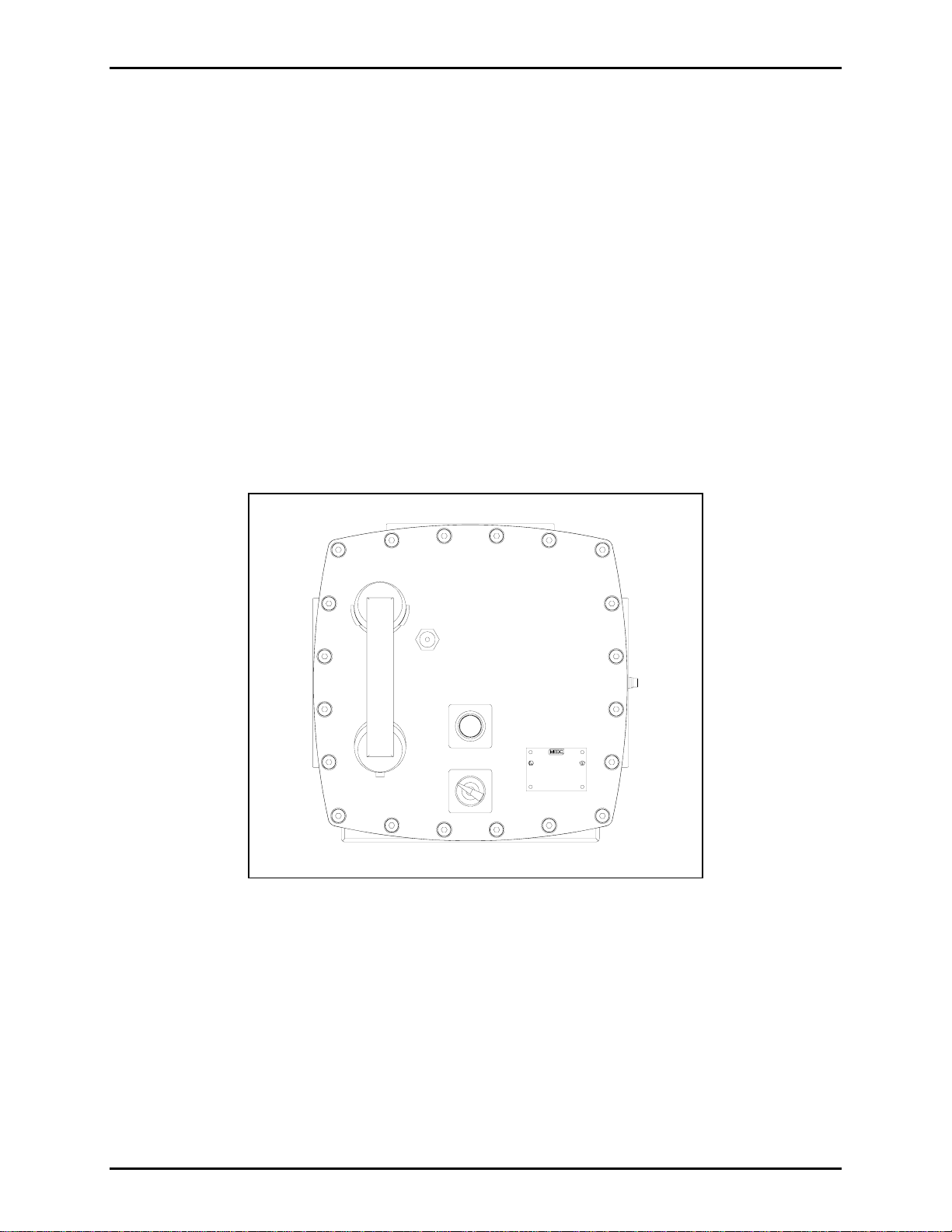
The assembly described in this manual is an explosion-proof enclosure, an intelligent speaker amplifier,
and handset designed to be installed in hazardous areas where combustible gases exist or may exist. The
extra thick cast aluminum enclosure, while not gas tight, is designed to withstand repeated internal
explosions without expelling gases hot enough to ignite the external atmosphere. This is accomplished
through the use of a precision machined enclosure opening flame-path that cools the exiting gases to a
temperature below the flash point of the external, explosive atmosphere.
How to Use the Assembly/Model
Application
The hazardous area Model 7805-821-EX SmartSeries Handset Station is designed to provide clear paging
communications even in high noise areas where explosive atmospheres exist or may exist.
The Model 7805-821-EX is BASEEFA approved to ATEX Standards Ex dib for Zone 1 Group IIC T5.
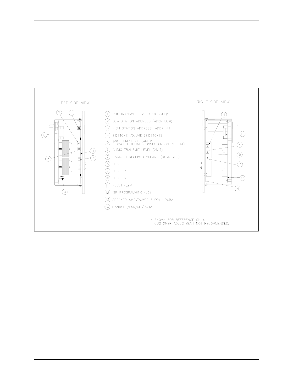
The intelligent SmartSeries Handset Station is designed for use on the GAI-Tronics multi-party system
cable or with an ADVANCE system. It includes micro-controllers that are programmed to:
•Receive and send data messages on the system cable
•Monitor and control handset
•Measure ambient noise and adjust speaker volume level
•Monitor and control optional external equipment

Pub. 42004-653L2B
Model 7805-821-EX SmartSeries Handset Station With RTU Page 2 of 22
\\s_eng\gtcproddocs\standard ioms - current release\42004 instr. manuals\42004-653l2b.doc
09/04
The SmartSeries station RTU is designed to be used with the SmartSeries amplifiers and handsets for use
in a standard multi-party Page/Party®system or with an ADVANCE system. It is also possible to control
an external device by activating and deactivating a single relay circuit located in the SmartSeries station
enclosure. This circuit is referred to as a relay output.
In addition to the relay output capability, the RTU also provides two inputs. These circuits provide an
interface to dry contact switches, (e.g., a pull box) which are monitored within the SmartSeries station.
The SmartSeries station reports any switch activation to the Master Control Unit (MCU).
The relay output is factory-set to be supervised through input #1. See Figure 7. However, you can elect
to use input 1 by disconnecting supervision for the relay output.
Hardware Configuration
External
The handset hangs on a cradle. When the handset is removed, a magnetic reed switch in the cradle
signals the off-hook status to a micro-controller within the assembly. To the right of the handset are a
handset cord, page push button, label, and a 5-party line selector switch.
Figure 1. Model 7805-821-EX/UL SmartSeries Handset Station

Pub. 42004-653L2B
Model 7805-821-EX SmartSeries Handset Station With RTU Page 3 of 22
\\s_eng\gtcproddocs\standard ioms - current release\42004 instr. manuals\42004-653l2b.doc
09/04
See Figure 2 for the Model 7805-821-EX cable gland entries. The base contains three M25 entries (two
fitted with plugs), two M20 entries, and one M16 entry.
NOTE
Ensure any unused openings are sealed with proper fittings per local standards.
Figure 2. Model 7805-821-EX Cable Gland Entries

Pub. 42004-653L2B
Model 7805-821-EX SmartSeries Handset Station With RTU Page 4 of 22
\\s_eng\gtcproddocs\standard ioms - current release\42004 instr. manuals\42004-653l2b.doc
09/04
Internal
The SmartSeries Handset Station contains:
•Chassis
•Speaker Amplifier/ Power Supply sub-assembly fixed to the front panel;
•Handset/FSK Modem/microcontroller with a plug at the top, pointing to the rear.
Figure 3. Model 701-902-EX SmartSeries Plug-in Amplifier—Side View

Pub. 42004-653L2B
Model 7805-821-EX SmartSeries Handset Station With RTU Page 5 of 22
\\s_eng\gtcproddocs\standard ioms - current release\42004 instr. manuals\42004-653l2b.doc
09/04
Block Diagram
P1 is the 16-pin male connector located on the back of the Speaker Amp/Power Supply PCBA. It plugs
into the socket located inside the cast aluminum enclosure. The socket provides connection to the multi-
party cable containing the Page/Party®lines and ac power. See Figure 4.
Connector J1A and J1B on the Speaker Amp/Power Supply connects regulated +5 V dc, +/-15 V dc, and
VRLY voltages along with control, monitoring, and line signals to the J1A and J1B on the Handset
Amp/FSK/µP PCBA. Connector J2 of the Speaker Amp/Power Supply PCBA connects to optional RTU
PCBA.
The Handset Amp/FSK/µP PCBA has connections to the handset and the hookswitch via spade terminal
connectors E1 to E7. The handset circuit is routed through an isolation barrier to ensure handset integrity.
The SmartSeries RTU allows three choices of operational configurations. Select the configuration that
best suits your need for circuits. The following table lists the RTU configurations:
Configuration Inputs Outputs
1 1 supervised input 1 supervised relay output (factory setting)
2 2 supervised inputs 0 relay output
3 2 supervised inputs 1 non-supervised relay output
Figure 4. Model 701-902-EX SmartSeries Handset Station Block Diagram

Pub. 42004-653L2B
Model 7805-821-EX SmartSeries Handset Station With RTU Page 6 of 22
\\s_eng\gtcproddocs\standard ioms - current release\42004 instr. manuals\42004-653l2b.doc
09/04
Configuration 1
In the first configuration, the relay output is supervised to continually ensure the integrity of the external
circuit. The first input, IN 1, is used to support supervision of the relay output circuit. This wiring
method requires the use of a 20 k-ohm, 2-watt resistor placed in parallel to the relay output device (e.g. a
beacon or strobe) as shown in Figure 5. Wire the terminating resistor as close as possible to the beacon.
Supervision is performed during non-activation of the relay output using IN 1. The second input, IN 2,
remains available for detecting switch activations. The following section describes switch wiring choices.
The RTU provides 120 V ac for beacon power on pins TB4-26, TB4-27, and TB4-28.
NOTE
This configuration is hardwired at the factory.
Figure 5. Beacon or Strobe

Pub. 42004-653L2B
Model 7805-821-EX SmartSeries Handset Station With RTU Page 7 of 22
\\s_eng\gtcproddocs\standard ioms - current release\42004 instr. manuals\42004-653l2b.doc
09/04
Configuration 2
The second configuration uses two supervised input circuits and does not make use of the single relay
output. This configuration is accomplished by interfacing to terminal block TB2 pins 12 and 13 for IN 1
and pins 14 and 15 for IN 2. The external dry contact switch, either normally open or normally closed
respectively, should be in parallel to a 15 k-ohm resistor as shown in Figure 6. A 5.1 k-ohm resistor
should be in series to the 15 k-ohm resistor. This provides a voltage divider network used to detect a
short or open across the external circuit’s cabling. This configuration requires that the orange wire from
TB3-23 going to the relay output circuit be disconnected so as not to interfere with supervised operation.
Another method of performing supervision using multiple switches is shown in Figure 7. This method
requires only one 20 k-ohm resistor that is placed in parallel to multiple normally open dry contact
switches at the end of line (EOL).
Figure 6. PLC or Switch Box
Normally Open and Normally Closed - Example
Figure 7. Input Line Supervision Multiple Switch - Example

Pub. 42004-653L2B
Model 7805-821-EX SmartSeries Handset Station With RTU Page 8 of 22
\\s_eng\gtcproddocs\standard ioms - current release\42004 instr. manuals\42004-653l2b.doc
09/04
Configuration 3
In the third configuration, the relay output circuit is non-supervised. This means the RTU can command a
system device to activate or deactivate without the integrity of the external circuit being verified. In this
configuration, both inputs are available.
NOTE
Unused inputs must be terminated at terminal block TB3 with a 20 k-ohm, 2-watt resistor.
Resistors are supplied with the units. See Figure 8.
Interfaces
The assembly interfaces to the multi-party cable, and to the external loudspeaker, via the 16-way
connector P1 and connector J1.
Pin No. Function Description Pin No. Function Description
1PL_L1 Party line (L1)9
PL_L2 Party line (L2)
2PG_L1 Page line (L1)10
PG_L2 Page line (L2)
3MT_L1 Mute (L1)11
MT_L2 Mute (L2)
4AUX0IN* Auxiliary input (0) 12 AUX1IN* Auxiliary input (1)
5SPKR_8 Speaker (8-ohm) 13 EGND Earth ground
6SPKR_16 Speaker (16-ohm) 14 SPKR_C Speaker (common)
7N/C No connection 15 N/C No connection
8AC_N AC neutral 16 AC_H AC hot
A ribbon connector supplied with the unit connects the SmartSeries relay circuit to the connector at the
base of the SmartSeries station.
Figure 8. Unused input

Pub. 42004-653L2B
Model 7805-821-EX SmartSeries Handset Station With RTU Page 9 of 22
\\s_eng\gtcproddocs\standard ioms - current release\42004 instr. manuals\42004-653l2b.doc
09/04
Wiring to the RTU is performed by connecting the external circuits to the appropriate lugs on the TB2
terminal block located on the rear panel on the enclosure. The following table shows the wiring for the
terminal blocks:
Terminal Block
Lug Number Label
TB2 - 12 IN 1
TB2 - 13 Common
TB2 - 14 IN 2
TB2 - 15 Common
TB4 - 26 Black (hot) 120 V ac 50/60 Hz, 3 amps max.
TB4 - 27 White (neutral) 120 V ac 50/60 Hz
TB4 - 28 Earth ground
The SmartSeries RTU is pre-wired from the factory to support one supervised input and one supervised
relay output. To disable the supervision of the relay output circuit by IN 1, disconnect the orange wire
going to the relay circuit card located at TB2-12. This is the only wiring modification necessary for any
of the three RTU configurations.
The supervised input and relay output functions are supported by the ADVANCE system.
Installation
Before installing SmartSeries equipment, design the system layout taking into consideration personnel
safety, operational function and convenience, and power cable length. In general, for 115 V ac systems
the total power cable length should not exceed one mile (1.6 km), but the length of cable between the
stations is not a critical factor.
However, it is a good practice to run a separate power feed to each station located in hazardous areas.
With a separate feed, individual stations can be de-energized for service or maintenance without affecting
the power supply and operation of the other stations in the hazardous area.

Pub. 42004-653L2B
Model 7805-821-EX SmartSeries Handset Station With RTU Page 10 of 22
\\s_eng\gtcproddocs\standard ioms - current release\42004 instr. manuals\42004-653l2b.doc
09/04
Mounting
NOTE:The mounting surface must be able to support 55 lbs. (25 kg).
1. Remove the front panel. Allow the front panel to hang from the rear of the enclosure by means of
two retaining straps during installation. The straps serve as personnel safety feature and as a
safeguard designed to ensure the front panel flame path is not nicked, dented or otherwise damaged
while mounting the enclosure. On stations with a selector switch, be sure that the switch is not
resting on the rear enclosure; this could break the switch wafers.
2. To maintain the explosion-proof integrity of the enclosure, all mounting hardware is located in non-
intrusive mounting holes under the front panel. The suggested mounting height of the station is
54 inches (137 cm). Use standard 1/2-inch socket head cap screws or M12 bolts to secure the
enclosure to a flat mounting surface.
3. After the enclosure is securely mounted, remove the plug-in amplifier:
•Disengage the 24-pin connector between the front panel and the plug-in amplifier.
•Remove the 4 screws that secure the amplifier to the standoffs, and retain.
•Pull the amplifier straight toward you to disengage the 16-pin connector from the enclosure.
•Set the amplifier aside in a safe place while completing the installation.
NOTE
The following instructions are provided to ensure compliance with the appropriate approval
standards. Select the version that applies to the equipment you have purchased based on approval
agency jurisdiction.
Figure 9. Mounting holes with dimensions

Pub. 42004-653L2B
Model 7805-821-EX SmartSeries Handset Station With RTU Page 11 of 22
\\s_eng\gtcproddocs\standard ioms - current release\42004 instr. manuals\42004-653l2b.doc
09/04
Follow the mounting instructions described above.
1. Make up cable core ends as required for connection to the terminal blocks in the enclosure base.
2. Dismantle the outer parts of the 25 mm Ex ‘d’ cable gland(s) for the system cable and 16 mm Ex ‘d’
cable gland for the speaker cable and thread them onto the cable(s) in the correct order.
3. Feed the cable end(s) into the enclosure through the gland body or bodies and reassemble the outer
gland parts as directed by the manufacturer.
4. Before tightening of the gland assembly, check that the slack in the cable inside the enclosure is
adequate but not excessive.
5. Connect cable cores to terminals following the wire colors as illustrated in Figure 10. The wire colors
correspond to GAI-Tronics 60072 Series system cable and 60070 for speaker cable. Connect the
wires carefully and completely to the terminal block. An improper termination may result in
diminished station performance.
6. Install the amplifier by aligning the 16-pin connector to the enclosure socket and pushing straight in.
Install the 4 screws retained previously.
7. Reconnect the 24-pin plug to the front cover.
8. Lift the front cover and inspect the gasket and machined rim for nicks, scratches, or other damage that
could compromise the integrity of the flame path seal.
9. Reconnect the 24-pin connector between the front panel and plug-in amplifier.
10. Secure the front cover in place using the bolts provided. Tighten the bolts alternately with bolts that
are diagonally opposite to ensure that the cover is evenly sealed.
NOTE
If acoustical feedback occurs between the speaker associated with the amplifier and the station
handset, the speaker can be muted by moving the violet wire on the enclosure on TB2 to
Terminal 7.

Pub. 42004-653L2B
Model 7805-821-EX SmartSeries Handset Station With RTU Page 12 of 22
\\s_eng\gtcproddocs\standard ioms - current release\42004 instr. manuals\42004-653l2b.doc
09/04
Figure 10. Multi-Party Wiring Detail

Pub. 42004-653L2B
Model 7805-821-EX SmartSeries Handset Station With RTU Page 13 of 22
\\s_eng\gtcproddocs\standard ioms - current release\42004 instr. manuals\42004-653l2b.doc
09/04
Operation
Complete the following steps to make a page announcement:
1. Lift the handset from the cradle.
2. Rotate the selector switch on the front cover to an unoccupied party line.
3. Depress and hold the page button on the front cover.
4. Speak directly into the microphone to broadcast your announcement over the loudspeakers.
5. Release the page button, and if requested, wait for a response.
The paged individual(s) responds by picking up a station handset and turning the selector switch (multi-
party stations only) to the requested party line. Other individuals can also pick up and join the
conversation at any time. Always return the handset to the cradle following a page or a party line
conversation.

Pub. 42004-653L2B
Model 7805-821-EX SmartSeries Handset Station With RTU Page 14 of 22
\\s_eng\gtcproddocs\standard ioms - current release\42004 instr. manuals\42004-653l2b.doc
09/04
Adjustments
This assembly includes one external control that permits adjustments to be made while the assembly is
mounted in its enclosure and several internal controls that are accessible only by removing the assembly
from its enclosure.
CAUTION
It is necessary to open the explosion-proof enclosure to make adjustments. Make adjustments only
when the conditions at your facility are such that no explosive atmospheres can be present.
There is a user adjustment for setting the speaker amplifier gain for the SmartVolume™ feature, which
has three components: Minimum Level, Offset Level, and VLC Level. Although they typically require
no adjustments, these volume levels can be set with the User Level Adjustment control (labeled USER
ADJ) located under the nameplate on the front panel. Use a small flat-blade screwdriver with an
insulated shaft at least 4 inches long to make adjustments.
To access the USER ADJ control, perform the following steps:
1. Unbolt and remove the front enclosure cover. Loosen (do not remove) the 2 screws that secure the
nameplate on the speaker amplifier.
2. Pivot the nameplate counterclockwise, exposing the access hole.
3. A guide behind the access hole helps direct the screwdriver to the USER ADJ control.
4. When you are done with the adjustment, pivot the nameplate clockwise into position, then tighten the
both screws.
Minimum Level
The Minimum Level adjustment sets the minimum output of the speaker amplifier. The amplifier can be
set from minimum to full output (12 watts into 8 ohms) in 100 discrete steps, or no output. The factory
default is step 20, providing 4 watts.
To adjust the Minimum Level, perform the following steps:
1. Turn USER ADJ fully counterclockwise and wait to hear a single beep over the station’s speaker.
This switches the station into the Minimum Level adjustment mode. If there is an audio signal on the
page line when the station enters this mode, you hear it over the speaker. Otherwise, you hear a
station-generated test tone.
2. Turn USER ADJ clockwise to the desired minimum speaker volume level.
The station remains in the Minimum Level adjustment mode for as long as USER ADJ is varying.
After USER ADJ has remained stable for five seconds, the station returns to its normal operating
mode.

Pub. 42004-653L2B
Model 7805-821-EX SmartSeries Handset Station With RTU Page 15 of 22
\\s_eng\gtcproddocs\standard ioms - current release\42004 instr. manuals\42004-653l2b.doc
09/04
Offset Level
The Offset Level adjustment causes the speaker amplifier to maintain a set difference between the
ambient level and the speaker output level. The SmartVolume™ feature measures the ambient noise at
the station’s speaker and adds the Offset Level to set the speaker amplifier gain. This keeps page
announcements louder than the ambient noise. The Offset Level can be set from 0 dB (the speaker output
level is the same as the ambient level) to 48 dB. A speaker should be set for 6 to 10 dB louder than the
ambient noise, so the factory default is 9 dB.
To adjust the Offset Level, perform the following steps:
NOTE There must be enough ambient noise for the station to sense. The exact level
depends upon the speaker type, but it is typically approximately 80 dB.
1. Turn USER ADJ fully clockwise and wait to hear two beeps over the station’s speaker.
This switches the station into the Offset Level adjustment mode. If there is an audio signal on the
page line when the station enters this mode, you hear it over the speaker. Otherwise, you hear a
station-generated test tone.
2. Turn USER ADJ counterclockwise to the desired speaker volume level.
The station remains in the Offset Level adjustment mode for as long as USER ADJ is varying. After
USER ADJ has remained stable for five seconds, the station returns to its normal operating mode.
VLC Level
The VLC Level adjustment sets the speaker amplifier gain for the Page Priority VLC feature to provide
an emergency output level. The amplifier can be set from minimum to full output (12 watts into 8 ohms)
in 100 discrete steps, or to no output. The factory default is step 10, but the System VLC Control feature
is usually disabled. To adjust the VLC Level, perform the following steps:
1. Have an assistant page from a station that forces the station being adjusted into VLC mode.
2. Turn USER ADJ fully counterclockwise and wait to hear two beeps over the station’s speaker.
This switches the station into the VLC Level adjustment mode.
3. Turn USER ADJ clockwise to the desired speaker volume level.
The station remains in the VLC Level adjustment mode for as long as USER ADJ is varying. After
USER ADJ has remained stable for five seconds, the station returns to its normal operating mode.

Pub. 42004-653L2B
Model 7805-821-EX SmartSeries Handset Station With RTU Page 16 of 22
\\s_eng\gtcproddocs\standard ioms - current release\42004 instr. manuals\42004-653l2b.doc
09/04
Internal Adjustments
Although they typically require no adjustments, the following volume levels can be set with internal
controls: Audio Transmit Level and Handset Receiver Volume.
To make an adjustment, it is necessary to remove the assembly from its enclosure and make a temporary
connection between the assembly and the enclosure. Turn a control clockwise to increase the volume or
threshold; turn it counterclockwise to decrease the volume or threshold. Use a small flat-blade
screwdriver with an insulated shaft to make adjustments.
To access the controls, perform the following steps:
1. Loosen the four captive screws that secure the front panel.
2. Remove the assembly from the enclosure. If the enclosure is equipped with an optional EOL Module
or SmartSeries Station RTU, be careful to not disconnect the ribbon cable on J3 of the Speaker
Amplifier/Power Supply PCBA.
3. Connect the assembly to the enclosure using a Model 10440-002 Maintenance Cable between P1 on
the assembly and J1 on the enclosure.
4. Locate and adjust the control on the appropriate PCBA.
5. When you are done with the adjustment:
a) Disconnect the Model 10440-002 Maintenance Cable.
b) Insert the assembly into the enclosure.
c) Tighten the 4 screws.
Audio Transmit Level
Use the control labeled XMIT LEVEL (on the Handset/FSK/µP PCBA) to adjust to the desired level the
handset microphone gain for page and party lines.
Handset Receiver Volume
Use the control labeled RCVR VOL (on the Handset/FSK/µP PCBA) to adjust to the desired level the
handset receiver volume for voice signals from a party line.

Pub. 42004-653L2B
Model 7805-821-EX SmartSeries Handset Station With RTU Page 17 of 22
\\s_eng\gtcproddocs\standard ioms - current release\42004 instr. manuals\42004-653l2b.doc
09/04
Other Controls
This assembly includes the following additional controls. These controls affect system performance;
therefore, only qualified GAI-Tronics personnel with the appropriate test equipment should make
adjustments. Tampering with these controls may void your warranty.
AGC Threshold
The control labeled AGC THRESH (on the Handset/FSK/µP PCBA) sets the level at which automatic
gain control (AGC) limits the handset microphone signal.
FSK Transmit Level
The control labeled XMIT LEVEL (on the Handset/FSK/µP PCBA) adjusts the level of the frequency
shift keying (FSK) signal transmitted to the page line. DO NOT ADJUST!
Sidetone Volume
The control labeled SIDETONE VOL (on the Handset/FSK/µP PCBA) adjusts the handset sidetone.

Pub. 42004-653L2B
Model 7805-821-EX SmartSeries Handset Station With RTU Page 18 of 22
\\s_eng\gtcproddocs\standard ioms - current release\42004 instr. manuals\42004-653l2b.doc
09/04
Maintenance
In order to verify and ensure explosion-proof integrity, perform regular preventive maintenance and
inspection checks on the GAI-Tronics explosion-proof enclosure. The GAI-Tronics Field Service
Department can formulate a service contract to suit specific preventive maintenance needs.
CAUTION
Remove power from the enclosure before performing any maintenance.
Use the following procedures to ensure reliable operation of your equipment:
1. Remove power from the enclosure.
2. Unbolt the cover, and remove amplifier from the enclosure.
3. Visually check the interior of the enclosure for signs of contamination. Contamination inside the
enclosure could mean that the conduit seals or cable gland seals have been compromised.
4. Ensure the gasket and hardware are in place and in good condition. Restore power to the unit.
In certain circumstances, it may be necessary to re-terminate wire connections to some or all of the
enclosures in a system. When this is done, strip the wires back to clean copper, reconnect to each
terminal.

Pub. 42004-653L2B
Model 7805-821-EX SmartSeries Handset Station With RTU Page 19 of 22
\\s_eng\gtcproddocs\standard ioms - current release\42004 instr. manuals\42004-653l2b.doc
09/04
Troubleshooting
The following suggestions are provided to aid a technician in troubleshooting:
Problem Solution
Integral speaker level requires
adjustment. Adjust the speaker volume control at the amplifier.
Outgoing conversation level requires
adjustment. Adjust microphone gain at the amplifier.
Incoming conversation level requires
adjustment. Adjust the receiver volume control at the amplifier.
Feedback/distortion (a hum or buzz
on the line) occurs during all
Page/Party®station operation.
•Adjust the receiver sidetone at the amplifier.
•The line may be improperly terminated. Inspect the system
cable for loose connections, shorts, and grounds. Line
balance assembly connections are critical.
Sidetone*requires adjustment.
*Hearing one’s own voice in the
receiver of the handset.
•Adjust the receiver sidetone at the amplifier.
•Check that the system cable connections to the resistors in
the line balance assembly are properly connected to line
balance assembly resistors.
Crosstalk occurs. One or more system cable pairs may be improperly terminated.
Visually inspect the system cable connections for accidental
crossing of the cable pairs or grounds.
Feedback during page of nearby
handset station. Use the muting feature in the amplifier enclosure at the terminal
blocks.
Station responds to polling messages
but the relay output does not
respond.
Check for trouble report from station if the output is being
supervised. The report will indicate what type of trouble has
occurred. If the message, “Supervised Output Circuit” is
reported, check relay circuit and supervision path.
Station does not respond to poll
message. Check and replace fuse on the back panel of the enclosure as
well as fuses on the SmartSeries device.
The following device fault message
received at the MCU:
“Supervised Input Circuit”
•Check that the input circuit is properly terminated.
•Check the external circuit connected to either input of the
RTU for a short or open. The input circuit number is
identified on the device fault message.
Device fault message is not received
but the input circuits do not activate
an alarm.
•Ensure that software configuration is set up to report the
alarm.
•Remove and replace the SmartSeries handset or amplifier.
A device fault is not reported to the
MCU but the output circuit does not
respond to an activation command.
Check and replace the SmartSeries station relay circuit card.
Relay output does not engage. Ensure the ribbon cable from the J2 connector to the RTU board
is attached correctly.

Pub. 42004-653L2B
Model 7805-821-EX SmartSeries Handset Station With RTU Page 20 of 22
\\s_eng\gtcproddocs\standard ioms - current release\42004 instr. manuals\42004-653l2b.doc
09/04
Specifications
Electrical
Voltage.....................................................................................90 to 140 V ac (120 V ac nominal) 50/60 Hz
Power consumed.................................. Zero/maximum signal (12 watts): 15 VA, 9 watts; 59 VA, 32 watts
Speaker Amplifier
Output:.............................................................................. 12 watts minimum, with nominal supply voltage
Output limiter:................................................................................... 13 watts (adjustable via configuration)
Frequency response.............................................................................. 350-6500 Hz, +0/-3 dB ref. to 1 kHz
Distortion ......................................................................................... 1% maximum THD @ 1 kHz, 12 watts
Input impedance........................................................................... 50 k-ohms nominal without FSK modem;
16k ohms nominal with FSK modem
Audio input from line............................................... 1.5 VRMS nominal (depends on distance) from 33 ohm
Handset
Output ................................................................................................... 1.5 VRMS nominal into 33-ohm load
Output limiter..................................................................................................................... 1.5 VRMS nominal
Frequency response.............................................................................. 350-6500 Hz, +0/-3 dB ref. to 1 kHz
Distortion ..................................................................................................... 1.5% maximum THD @ 1 kHz
FSK Modem
FSK output to line................................................................................... 0.7 VRMS 2 Vp-p into 33-ohm load
FSK frequency range .................................................................................................................... 30-33 kHz
Relay Board
Contact inputs ..........................................................................................NO/NC, maintained or momentary
Output voltage.................................................................................................................................. 120 V ac
Output current (maximum) .................................................................................................................. 1 amp
SmartVolumeTM
Dynamic range................................................................................................................... 62 to 100 dB SPL
Offset (above ambient) user adjust ............................................................................................... 0 to 48 dB
Minimum user adjust ..................................................................................................Off; 85 to 125 dB SPL
Speaker/Wire Monitor
Dynamic range......................................................................................................................27 to 65 dB SPL
Recommended environment .....................................................................................Greater than 50 dB SPL
Table of contents
Other Hubbell Handset manuals