Huber Pilot ONE User manual

Manual
Flow Rate Measurement
and Control
Unistat
V1.0.0


MANUAL
V1.0.0en/30.03.16 Errors and omissions excepted. Flow Rate Measurement and Control
3
Flow Rate Measurement
and Control
VALID FOR:
Unistat® Models

MANUAL
Flow Rate Measurement and Control Errors and omissions excepted. V1.0.0en/30.03.16
4
Standard variant:
Variant 1 and 2:
Variant 3:
Variant 4 and 5 (with plate heat exchanger):
Standard configuration
variants overview

MANUAL
V1.0.0en/30.03.16 Errors and omissions excepted. Flow Rate Measurement and Control
5
Standard variant:
Variant 1 and 2:
Variant 3:
Variant 4 and 5 (with plate heat exchanger):
Variants overview for
remote operation

MANUAL
Flow Rate Measurement and Control Errors and omissions excepted. V1.0.0en/30.03.16
6

MANUAL
V1.0.0en/30.03.16 Errors and omissions excepted. Flow Rate Measurement and Control
7
Table of contents
V1.0.0en/30.03.16
1Application ................................................................................11
2Standard configuration ..............................................................12
2.1 Standard variant (flow rate control) .............................................................12
2.1.1 Commissioning................................................................................................ 13
2.1.2 Description of function ................................................................................... 13
2.1.3Setup mode..................................................................................................... 13
2.1.3.1 Speed control.............................................................................................. 13
2.1.3.2 Pressure control.......................................................................................... 13
2.1.4 Shutting down................................................................................................. 13
2.2 Variant 1 (flow rate measurement) .............................................................. 14
2.2.1 Commissioning................................................................................................ 15
2.2.1.1 Installing the mass flow meter ................................................................... 15
2.2.1.2 Connecting connections.............................................................................. 15
2.2.2 Description of function ................................................................................... 16
2.2.3 Setup mode..................................................................................................... 16
2.2.3.1 Mass flow meter ......................................................................................... 16
2.2.4 Shutting down................................................................................................. 17
2.2.4.1 Disconnecting connections ......................................................................... 17
2.2.4.2 Deinstalling the mass flow meter ............................................................... 17
2.3 Variant 2 (flow rate control) .........................................................................18
2.3.1 Commissioning................................................................................................ 19
2.3.1.1 Installing the mass flow meter ................................................................... 19
2.3.1.2 Connecting connections.............................................................................. 19
2.3.2 Description of function ................................................................................... 20
2.3.3 Setup mode..................................................................................................... 20
2.3.3.1 Mass flow meter ......................................................................................... 20
2.3.4 Shutting down................................................................................................. 21
2.3.4.1 Disconnecting connections ......................................................................... 21
2.3.4.2 Deinstalling the mass flow meter ............................................................... 21
2.4 Variant 3 (flow rate control) .........................................................................22
2.4.1 Commissioning................................................................................................ 23
2.4.1.1 Installing VPC-Bypass and mass flow meter............................................... 23
2.4.1.2 Connecting connections.............................................................................. 23
2.4.2 Description of function ................................................................................... 24
2.4.3 Setup mode..................................................................................................... 24
2.4.3.1 Mass flow meter ......................................................................................... 24
2.4.3.2 VPC-Bypass ................................................................................................. 25
2.4.4 Shutting down................................................................................................. 25
2.4.4.1 Disconnecting connections ......................................................................... 25
2.4.4.2 Deinstalling VPC-Bypass and mass flow meter........................................... 25
2.5 Variant 4 (flow rate control) .........................................................................26
2.5.1 Commissioning................................................................................................ 27
2.5.1.1 Installing the VPC-Bypass, the pressure booster pump Unipump and the
mass flow meter ......................................................................................... 27
2.5.1.2 Connecting connections.............................................................................. 27
2.5.2 Description of function ................................................................................... 28
2.5.3 Setup mode..................................................................................................... 28
2.5.3.1 Mass flow meter ......................................................................................... 28
2.5.3.2 VPC-Bypass ................................................................................................. 29
2.5.3.3 Pressure booster pump Unipump ............................................................... 29
2.5.4 Shutting down................................................................................................. 29
2.5.4.1 Disconnecting connections ......................................................................... 29
2.5.4.2 Deinstalling the VPC-Bypass, the pressure booster pump Unipump and the
mass flow meter ......................................................................................... 29
2.6 Variant 5 (flow rate control) .........................................................................30
2.6.1 Commissioning................................................................................................ 31
2.6.1.1 Installing the plate heat exchanger, the VPC-Bypass, the pressure booster
pump Unipump and the mass flow meter .................................................. 31
2.6.1.2 Connecting connections.............................................................................. 31
2.6.2 Description of function ................................................................................... 32
2.6.3 Setup mode..................................................................................................... 32
2.6.3.1 Mass flow meter ......................................................................................... 32
2.6.3.2 VPC-Bypass ................................................................................................. 33

MANUAL
Flow Rate Measurement and Control Errors and omissions excepted. V1.0.0en/30.03.16
8
2.6.3.3 Pressure booster pump Unipump ............................................................... 33
2.6.4 Shutting down................................................................................................. 33
2.6.4.1 Disconnecting connections ......................................................................... 33
2.6.4.2 Deinstalling the plate heat exchanger, the VPC-Bypass, the pressure
booster pump Unipump and the mass flow meter ..................................... 33
3Configuration: Remote operation ..............................................34
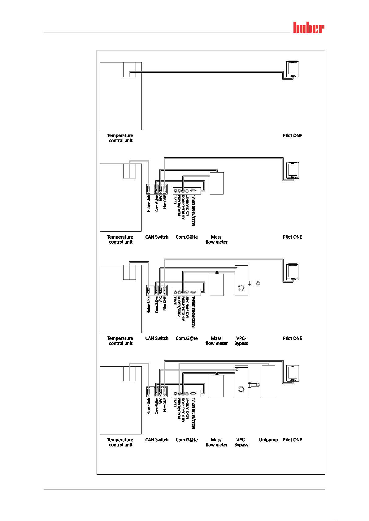
3.1 Standard variant (flow rate control) .............................................................34
3.1.1 Commissioning................................................................................................ 35
3.1.2 Description of function ................................................................................... 35
3.1.3 Setup mode..................................................................................................... 35
3.1.3.1 Speed control.............................................................................................. 35
3.1.3.2 Pressure control.......................................................................................... 35
3.1.4 Shutting down................................................................................................. 35
3.2 Variant 1 (flow rate measurement) .............................................................. 36
3.2.1 Commissioning................................................................................................ 37
3.2.1.1 Installing the mass flow meter ................................................................... 37
3.2.1.2 Connecting connections.............................................................................. 37
3.2.2 Description of function ................................................................................... 38
3.2.3 Setup mode..................................................................................................... 38
3.2.3.1 Mass flow meter ......................................................................................... 38
3.2.4 Shutting down................................................................................................. 39
3.2.4.1 Disconnecting connections ......................................................................... 39
3.2.4.2 Deinstalling the mass flow meter ............................................................... 39
3.3 Variant 2 (flow rate control) .........................................................................40
3.3.1 Commissioning................................................................................................ 41
3.3.1.1 Installing the mass flow meter ................................................................... 41
3.3.1.2 Connecting connections.............................................................................. 41
3.3.2 Description of function ................................................................................... 42
3.3.3 Setup mode..................................................................................................... 42
3.3.3.1 Mass flow meter ......................................................................................... 42
3.3.4 Shutting down................................................................................................. 43
3.3.4.1 Disconnecting connections ......................................................................... 43
3.3.4.2 Deinstalling the mass flow meter ............................................................... 43
3.4 Variant 3 (flow rate control) .........................................................................44
3.4.1 Commissioning................................................................................................ 45
3.4.1.1 Installing VPC-Bypass and mass flow meter............................................... 45
3.4.1.2 Connecting connections.............................................................................. 45
3.4.2 Description of function ................................................................................... 46
3.4.3 Setup mode..................................................................................................... 46
3.4.3.1 Mass flow meter ......................................................................................... 46
3.4.3.2 VPC-Bypass ................................................................................................. 47
3.4.4 Shutting down................................................................................................. 47
3.4.4.1 Disconnecting connections ......................................................................... 47
3.4.4.2 Deinstalling VPC-Bypass and mass flow meter........................................... 47
3.5 Variant 4 (flow rate control) .........................................................................48
3.5.1 Commissioning................................................................................................ 49
3.5.1.1 Installing the VPC-Bypass, the pressure booster pump Unipump and the
mass flow meter ......................................................................................... 49
3.5.1.2 Connecting connections.............................................................................. 49
3.5.2 Description of function ................................................................................... 50
3.5.3 Setup mode..................................................................................................... 50
3.5.3.1 Mass flow meter ......................................................................................... 50
3.5.3.2 VPC-Bypass ................................................................................................. 51
3.5.3.3 Pressure booster pump Unipump ............................................................... 51
3.5.4 Shutting down................................................................................................. 51
3.5.4.1 Disconnecting connections ......................................................................... 51
3.5.4.2 Deinstalling the VPC-Bypass, the pressure booster pump Unipump and the
mass flow meter ......................................................................................... 51
3.6 Variant 5 (flow rate control) .........................................................................52
3.6.1 Commissioning................................................................................................ 53
3.6.1.1 Installing the plate heat exchanger, the VPC-Bypass, the pressure booster
pump Unipump and the mass flow meter .................................................. 53
3.6.1.2 Connecting connections.............................................................................. 53
3.6.2 Description of function ................................................................................... 54
3.6.3 Setup mode..................................................................................................... 54
3.6.3.1 Mass flow meter ......................................................................................... 54
3.6.3.2 VPC-Bypass ................................................................................................. 55
3.6.3.3 Pressure booster pump Unipump ............................................................... 55
3.6.4 Shutting down................................................................................................. 55

MANUAL
V1.0.0en/30.03.16 Errors and omissions excepted. Flow Rate Measurement and Control
9
3.6.4.1 Disconnecting connections ......................................................................... 55
3.6.4.2 Deinstalling the plate heat exchanger, the VPC-Bypass, the pressure
booster pump Unipump and the mass flow meter ..................................... 55

MANUAL
Flow Rate Measurement and Control Errors and omissions excepted. V1.0.0en/30.03.16
10

Application
Chapter 1 MANUAL
V1.0.0en/30.03.16 Errors and omissions excepted. Flow Rate Measurement and Control
11
1Application
Depending on the temperature control unit model and accessories, Huber provides various variants
for flow rate measurement and control.
This manual describes the individual variants including hardware requirements, commissioning,
functional description and setup mode.

Standard configuration
MANUAL Chapter 2
Flow Rate Measurement and Control Errors and omissions excepted. V1.0.0en/30.03.16
12
2Standard configuration
2.1 Standard variant (flow rate control)
For temperature control units with a speed-controlled pump.
Required hardware
Required documentation
Temperature control unit
Operation manual of the temperature control unit
Schematic representa-
tion of variant
Prerequisites:

Standard configuration
Chapter 2 MANUAL
V1.0.0en/30.03.16 Errors and omissions excepted. Flow Rate Measurement and Control
13
2.1.1 Commissioning
Commission the temperature control unit as described in the operation manual (Section »Commis-
sioning«).
2.1.2 Description of function
In the standard variant, the flow rate is controlled by the speed-controlled pump built into the tem-
perature control unit.
2.1.3 Setup mode
Install the temperature control unit as described in the operation manual (Section »Setup mode«).
In Pilot ONE, the flow rate can be controlled by speed control or pressure control. The factory set-
ting of the temperature control unit is: Speed control, 3500 rpm.
The steps below must be performed as well.
2.1.3.1 Speed control
PROCEDURE
Go to the “Categories Menu”.
Tap on the category “System Settings”.
Tap on the category “Pump”.
Tap on the sub-category “Control Mode”.
Tap on the dialog entry “Speed Control”.
Confirm your choice by tapping on “OK”.
Tap on the menu item “Pump/ RPM”.
Enter the new speed using the number keypad that appears. You can enter a speed of min. 1500
rpm to max. 3500 rpm.
Confirm your choice by tapping on “OK”.
Continue with the instructions in the operation manual of the temperature control unit.
2.1.3.2 Pressure control
PROCEDURE
Go to the “Categories Menu”.
Tap on the category “System Settings”.
Tap on the category “Pump”.
Tap on the sub-category “Control Mode”.
Tap on the dialog entry “Pressure Control”.
Confirm your choice by tapping on “OK”.
Tap on the menu item “Pressure (Bypass)”.
Enter the new pump pressure using the number keypad that appears. You can read the current
pump pressure in this view, if you want to control the pump pressure during operation.
Confirm your choice by tapping on “OK”.
Continue with the instructions in the operation manual of the temperature control unit.
2.1.4 Shutting down
Shut down the temperature control unit as described in the operation manual (Section »Shutting
down«).
INFORMATION
.

Standard configuration
MANUAL Chapter 2
Flow Rate Measurement and Control Errors and omissions excepted. V1.0.0en/30.03.16
14
2.2 Variant 1 (flow rate measurement)
For temperature control units with or without a speed-controlled pump.
Required hardware
Required documentation
Temperature control unit
Operation manual of the temperature control unit
Com.G@te
Operation manual of the temperature control unit
CAN Switch
–
Mass flow meter
Operation manual of the mass flow meter
Connecting cables
–
Schematic representa-
tion of variant
Prerequisites:

Standard configuration
Chapter 2 MANUAL
V1.0.0en/30.03.16 Errors and omissions excepted. Flow Rate Measurement and Control
15
2.2.1 Commissioning
Commission the temperature control unit as described in the operation manual (Section »Commis-
sioning«). Also follow the operation manual of the mass flow meter.
The steps below must be performed as well.
2.2.1.1 Installing the mass flow meter
PROCEDURE
Install the mass flow meter in the building. Proceed as described in the operation manual of the
mass flow meter.
Install the mass flow meter in the thermal fluid circuit. Proceed as described in the operation
manual of the mass flow meter. See above figure »Schematic representation of the temperature
control unit«.
2.2.1.2 Connecting connections
PROCEDURE
Connect the jack >Huber-Unit< on the CAN Switch to the jack >RS232 Serial (with adapter ca-
ble)< on the temperature control unit.
Connect the jack >Com.G@te< on the CAN Switch to the jack on the side of the Com.G@te unit.
Connect the jack >VPC< on the CAN Switch to the mass flow meter. The mass flow meter receives
its voltage supply via the jack >VPC<.
Connect the mass flow meter to the jack >AIF Reg-E-Prog< on the Com.G@te unit.
Schematic representa-
tion of the temperature
control unit

Standard configuration
MANUAL Chapter 2
Flow Rate Measurement and Control Errors and omissions excepted. V1.0.0en/30.03.16
16
2.2.2 Description of function
The mass flow meter detects and outputs the flow rate of the thermal fluid. You cannot control the
flow rate in this variant.
2.2.3 Setup mode
Install the temperature control unit as described in the operation manual (Section »Setup mode«).
Also follow the operation manual of the mass flow meter.
The steps below must be performed as well.
2.2.3.1 Mass flow meter
Depending on the mass flow meter used, readings are output as current or voltage. Follow these
steps to calibrate the mass flow meter on the Pilot ONE.
PROCEDURE
Go to the “Categories Menu”.
Tap on the category “Interfaces”.
Tap on the category “Analogue Interface”.
Tap on the sub-category “Input”.
Tap on the sub-category “Current/Voltage switch”.
Depending on the mass flow meter used, tap on the entry “Current” or “Voltage”.
Confirm your choice by tapping on “OK”.
Tap the required entry “Trigger an alarm” or “No alarm”.
Confirm your choice by tapping on “OK”.
Tap on the sub-category “Input Funct./Measuring range”.
Tap on the entry “Thermofluid flow”.
Confirm your choice by tapping on “OK”.
Enter the min. value, using the numeric keypad that appears. Refer to the documentation of the
mass flow meter for the min. value.
Confirm your entry by tapping on “OK”.
Enter the max. value, using the numeric keypad that appears. Refer to the documentation of the
mass flow meter for the max. value.
Tap on the sub-category “Adjustment”.
Tap on the entry “Adjust current value”.
Confirm your choice by tapping on “OK”.
Tap on the entry “Adjust low value”.
Confirm your choice by tapping on “OK”.
Read the Note and confirm by tapping on “OK”.
Enter the value, using the numeric keypad that appears. The value is displayed on the mass flow
meter.
Confirm your entry by tapping on “OK”.
Tap on the sub-category “Adjustment”.
Tap on the entry “Adjust current value”.
Confirm your choice by tapping on “OK”.
Tap on the entry “Adjust high value”.
Confirm your choice by tapping on “OK”.
Read the Note and confirm by tapping on “OK”.
Enter the value, using the numeric keypad that appears. The value is displayed on the mass flow
meter.
Confirm your entry by tapping on “OK”. The mass flow meter has been calibrated.
Continue with the instructions in the operation manual of the temperature control unit.

Standard configuration
Chapter 2 MANUAL
V1.0.0en/30.03.16 Errors and omissions excepted. Flow Rate Measurement and Control
17
2.2.4 Shutting down
Shut down the temperature control unit as described in the operation manual (Section »Shutting
down«). Also follow the operation manual of the mass flow meter.
The steps below must be performed as well.
2.2.4.1 Disconnecting connections
PROCEDURE
Disconnect the jack >Huber-Unit< on the CAN Switch from the jack >RS232 Serial (with adapter
cable)< on the temperature control unit.
Disconnect the jack >Com.G@te< on the CAN Switch from the jack on the side of the Com.G@te
unit.
Disconnect the jack >VPC< on the CAN Switch from the mass flow meter.
Disconnect the mass flow meter from the jack >AIF Reg-E-Prog< on the Com.G@te unit.
2.2.4.2 Deinstalling the mass flow meter
PROCEDURE
Deinstall the mass flow meter from the thermal fluid circuit. Proceed as described in the opera-
tion manual of the mass flow meter.
Deinstall the mass flow meter from the building. Proceed as described in the operation manual of
the mass flow meter.

Standard configuration
MANUAL Chapter 2
Flow Rate Measurement and Control Errors and omissions excepted. V1.0.0en/30.03.16
18
2.3 Variant 2 (flow rate control)
For temperature control units with a speed-controlled pump.
Required hardware
Required documentation
Temperature control unit
Operation manual of the temperature control unit
Com.G@te
Operation manual of the temperature control unit
CAN Switch
–
Mass flow meter
Operation manual of the mass flow meter
Connecting cables
–
Schematic representa-
tion of variant
Prerequisites:

Standard configuration
Chapter 2 MANUAL
V1.0.0en/30.03.16 Errors and omissions excepted. Flow Rate Measurement and Control
19
2.3.1 Commissioning
Commission the temperature control unit as described in the operation manual (Section »Commis-
sioning«). Also follow the operation manual of the mass flow meter.
The steps below must be performed as well.
2.3.1.1 Installing the mass flow meter
PROCEDURE
Install the mass flow meter in the building. Proceed as described in the operation manual of the
mass flow meter.
Install the mass flow meter in the thermal fluid circuit. Proceed as described in the operation
manual of the mass flow meter. See above figure »Schematic representation of the temperature
control unit«.
2.3.1.2 Connecting connections
PROCEDURE
Connect the jack >Huber-Unit< on the CAN Switch to the jack >RS232 Serial (with adapter ca-
ble)< on the temperature control unit.
Connect the jack >Com.G@te< on the CAN Switch to the jack on the side of the Com.G@te unit.
Connect the jack >VPC< on the CAN Switch to the mass flow meter. The mass flow meter receives
its voltage supply via the jack >VPC<.
Connect the mass flow meter to the jack >AIF Reg-E-Prog< on the Com.G@te unit.
Schematic representa-
tion of the temperature
control unit

Standard configuration
MANUAL Chapter 2
Flow Rate Measurement and Control Errors and omissions excepted. V1.0.0en/30.03.16
20
2.3.2 Description of function
The mass flow meter detects the flow rate of the thermal fluid. In this variant, the flow rate is con-
trolled by the speed-controlled pump built into the temperature control unit.
2.3.3 Setup mode
Install the temperature control unit as described in the operation manual (Section »Setup mode«).
Also follow the operation manual of the mass flow meter.
The steps below must be performed as well.
2.3.3.1 Mass flow meter
Depending on the mass flow meter used, readings are output as current or voltage. Follow these
steps to calibrate the mass flow meter on the Pilot ONE.
PROCEDURE
Go to the “Categories Menu”.
Tap on the category “Interfaces”.
Tap on the category “Analogue Interface”.
Tap on the sub-category “Input”.
Tap on the sub-category “Current/Voltage switch”.
Depending on the mass flow meter used, tap on the entry “Current” or “Voltage”.
Confirm your choice by tapping on “OK”.
Tap the required entry “Trigger an alarm” or “No alarm”.
Confirm your choice by tapping on “OK”.
Tap on the sub-category “Input Funct./Measuring range”.
Tap on the entry “Thermofluid flow”.
Confirm your choice by tapping on “OK”.
Enter the min. value, using the numeric keypad that appears. Refer to the documentation of the
mass flow meter for the min. value.
Confirm your entry by tapping on “OK”.
Enter the max. value, using the numeric keypad that appears. Refer to the documentation of the
mass flow meter for the max. value.
Tap on the sub-category “Adjustment”.
Tap on the entry “Adjust current value”.
Confirm your choice by tapping on “OK”.
Tap on the entry “Adjust low value”.
Confirm your choice by tapping on “OK”.
Read the Note and confirm by tapping on “OK”.
Enter the value, using the numeric keypad that appears. The value is displayed on the mass flow
meter.
Confirm your entry by tapping on “OK”.
Tap on the sub-category “Adjustment”.
Tap on the entry “Adjust current value”.
Confirm your choice by tapping on “OK”.
Tap on the entry “Adjust high value”.
Confirm your choice by tapping on “OK”.
Read the Note and confirm by tapping on “OK”.
Enter the value, using the numeric keypad that appears. The value is displayed on the mass flow
meter.
Confirm your entry by tapping on “OK”. The mass flow meter has been calibrated.
Continue with the instructions in the operation manual of the temperature control unit.
Other manuals for Pilot ONE
4
Table of contents
Other Huber Control Unit manuals
Popular Control Unit manuals by other brands

Zennio
Zennio GetFace IP Assembly instructions

Dantel
Dantel 46019 Installation & operation manual

Kessel
Kessel Staufix FKA Standard Installation and operating manual

Velleman
Velleman VMM005 user manual

Siemens
Siemens SIDOOR AT40 System manual

Genebre
Genebre 2220 Installation, operation and maintenance manual