manuals.online logo
Brands
  1. Home
  2. •
  3. Brands
  4. •
  5. Omron
  6. •
  7. Control Unit
  8. •
  9. Omron 3G3FV-PPG Series User manual

Omron 3G3FV-PPG Series User manual

!
!
!
!
!
!
!
!
!
!
3G3FV-PPGj2
PG Speed Control Card
(For the 3G3FV only)
INSTRUCTION SHEET
Thank you for purchasing this OMRON product. Please read this
instruction sheet and thoroughly familiarize yourself with the func-
tions and characteristics of the product before use. This instruc-
tion sheet describes procedures for mounting and wiring the
3G3FV-PPGj2 PG Speed Control Card, and should be read in
conjunction with the 3G3FV Inverter User’s Manual (I516). Please
retain this sheet for future reference.
OMRON Corporation
EOMRON Corporation 1996 All Rights Reserved Cat. No. I518-E1-1
Safety Precautions
Before attempting to operate the PG Speed Control Card, be sure to
thoroughly familiarize yourself with the information contained in this
instruction sheet and those of any other applicable equipment, make
sure that you have a working knowledge about the equipment, and
make sure that you are well versed on all safety procedures and pre-
cautionary items in order to ensure the safe and proper use of the
OMRON Inverter and other peripheral devices.
Since diagrams in this instruction sheet may be shown with covers
and protective shielding removed in order to provide more detailed
explanations, make sure that covers and protective shielding are re-
placed as stipulated prior to using the product, and then use the prod-
uct only as outlined in the User’s Manual.
Be sure to contact our sales representative if the product is to be left
in storage for an extended period of time.
Make sure that this instruction sheet and other applicable manuals
are readily available to equipment operators.
Make sure that this instruction sheet is readily available once it is
read.
•The precautionary items list critical information for safety. Be sure
to heed these items at all times.
•The following conventions are used to indicate and classify pre-
cautions in this instruction sheet.
DANGER! Not following a precaution given as a “DAN-
GER” is likely to result in fatal or serious injury.
WARNING Not following a precaution given as a
“WARNING” may result in fatal or serious injury.
Caution Not following a precaution given as a “Caution”
can result in injury to people or damage to the
product or system.
Items listed under caution may also have serious consequences de-
pending on the circumstances, so be sure to heed these items at all
times.
Mounting
WARNING Never reach inside the Inverter as this may
result in an electrical shock.
WARNING Do not mount, remove, or wire Optional Cards
without first shutting the Inverter power OFF and
waiting until the prescribed amount of time
(indicated on the front cover of the Inverter) has
passed after all indicators on the Inverter are no
longer lit. Failure to do so may result in an
electrical shock.
WARNING Do not nick, apply undue stress, place heavy
objects on, or sandwich cables. Otherwise, this
may result in an electrical shock.
Caution Do not touch the elements of Optional Cards.
Otherwise, this may result in injury due to elec-
trical shock.
Connections and Settings
Caution Do not change settings unless absolutely nec-
essary. Otherwise, this will result in injury or
equipment damage.
Caution Do not mount or remove an Optional Card with
Inverter power ON. Otherwise, this will result in
injury or equipment damage.
Caution Be sure to connect the ground wire (E) of
Optional Cards. Otherwise, this may result in
equipment damage or faulty operation due to
noise.
Description
The 3G3FV-PPGj2 PG Speed Control Card is an Optional Card
used only with the SYSDRIVE 3G3FV Inverter.
This Optional Card controls motor speed and feeds back speed in-
formation to the Inverter from pulse generators (speed detectors,
such as encoders and pulse generators).
The Card is mounted on a 3G3FV Inverter control circuit board.
Nomenclature
•3G3FV-PPGA2 •3G3FV-PPGD2
TA2 shielded-wire connec-
tion terminal: Shielded wire
connection for an input wire
TA1 I/O terminal
Ground wire E
Connects to the 12 (G)
terminal of the control
circuit board.
TA2 shielded-wire connec-
tion terminal: Shielded wire
connection for an input wire
TA1 I/O terminal
Ground wire E
Connects to the 12 (G)
terminal of the control
circuit board.
•3G3FV-PPGB2 •3G3FV-PPGX2
TA3 shielded-wire connec-
tion terminal: Shielded wire
connection for an input wire
TA1 input terminal
Ground wire E
Connects to the 12 (G)
terminal of the control
circuit board.
TA3 shielded-wire connec-
tion terminal: Shielded wire
connection for an input wire
TA1 input terminal
Ground wire E
Connects to the 12 (G)
terminal of the control
circuit board.
TA2 output
terminal TA2 output
terminal
Specifications
Model Control
mode Input speci-
fications Maximum
response
frequency
Output
specifica-
tions
3G3FV-
PPGA2 V/f with PG
feedback
mode
Single pulse
input
Open
collector
output
compatible
30 kHz (50%
duty) Pulse monitor
output
Voltage
output
12 VDC
(±10%),
20 mA max.
3G3FV-
PPGB2 Flux vector
control mode A/B-phase
pulse input
Open
collector
output
compatible
30 kHz (50%
duty) A/B phase
pulse monitor
output
Open
collector
output
24 VDC max.
30 mA max.
3G3FV-
PPGD2 V/f with PG
feedback
mode
Single pulse
input
RS-422 level
input
300 kHz
(50% duty) Pulse monitor
output
RS-422 level
output
3G3FV-
PPGX2 Flux vector
control mode A/B/Z-phase
pulse input
RS-422 level
input
300 kHz
(50% duty) A/B/Z-phase
pulse monitor
output
RS-422 level
output
Note Inverter speed control accuracy falls off at frequency bands
below 50 Hz.
Mounting Procedure
1, 2, 3... 1. Be sure to turn OFF the main Inverter power supply,
wait at least 1 minute (at least 3 minutes for 30-kW-or-
higher Inverters), remove the front cover of the Inverter,
and make sure the charge indicator is not lit.
2. The PG Speed Control Card is an option A. Mount the
Card in the option-A location as shown in the diagram
below.
3. Insert the spacer that is provided into the spacer mount-
ing hole located on the mounting base of the Inverter.
There are 2 holes located on 3.7-kW-or-lower Inverters.
Insert the spacer in the hole on the 7CN side. Be very
careful because spacers cannot be removed if they are
inserted in the wrong hole.
4. Proceed in order with steps Aand Bin the enlarged
view below. Align the PG Speed Control Card and the
supports, make sure the connector on the Card is
aligned with the option-A connector, and then push the
spacer through the spacer mounting hole on the Card.
(Side View a)
Make sure the 4CN positions are properly aligned, and
push the spacer through the hole until it clicks into
place.
5. Connect the ground wire of the Card to the FG terminal
12(E) on the Inverter control circuit board.
Front View Side View
PG Speed
Control Card Spacer mounting hole
4CN
option-A
connector
2CN
option-C
connector
3CN
option-D
connector
Option A Control
circuit
board
Option C
Option D
Option-A mounting spacer
(Accessory: SRNT41028-9)
Inverter
mounting base
PG Speed
Control Card
Inverter
mounting base
Spacer mounting
hole
Control
circuit board
Spacer
Mounting
base side
Option A side
Spacer mounting
Enlarged View
Wiring
Description of PG Speed Control Card Terminal Blocks
•3G3FV-PPGA2 (For V/f With PG Feedback Mode Only)
Terminal No. Description Specification
TA1 1Pulse generator 12 VDC (±5%), 200 mA max.
2power supply 0 VDC (Power supply ground)
3+12-V/open
collector switching This terminal switches between
12-V voltage input and open
4collector switching 12-V voltage input and open
collector input. Short pins 3 and
4 for open collector input.
5Pulse input H: +4 to 12 V,
L: +1 V max. (30-kHz maximum
response frequency)
6Pulse input common
7Pulse monitor 12 VDC (±10%), 20 mA max.
8output Pulse monitor output common
TA2 (E) Shielded wire
connection ---
•3G3FV-PPGB2 (For Flux Vector Control Mode Only)
Terminal No. Description Specification
TA1 1Pulse generator 12 VDC (±5%), 200 mA max.
2power supply 0 VDC (Power supply ground)
3A-phase pulse
input H: +8 to 12 V,
L: +1 V max. (30 kHz maximum
response frequency)
4Pulse input common
5B-phase pulse
input H: +8 to 12 V,
L: +1 V max. (30 kHz maximum
response frequency)
6Pulse input common
TA2 1A-phase monitor
output Open collector output: 24 VDC
max., 30 mA max.
2A-phase monitor output common
3B-phase monitor
output Open collector output: 24 VDC
max., 30 mA max.
4B-phase monitor output common
TA2 (E) Shielded-wire
connection ---
•3G3FV-PPGD2 (For V/f With PG Feedback Mode Only)
Terminal No. Description Specification
TA1 1Pulse generator 12 VDC (±5%), 200 mA max.
2power supply 0 VDC (Power supply ground)
35 VDC (±5%), 200 mA max.
4Pulse input + Line driver input (RS-422 level
input)
5Pulse input –input)
300-kHz maximum response
frequency
6 Common ---
7Pulse monitor
output + Line driver output (RS-422 level
output)
8Pulse monitor
output –
TA2 (E) Shielded-wire
connection ---
Note 5 VDC and 12 VDC cannot be used simultaneously.
•3G3FV-PPGX2 (For Flux Vector Control Mode Only)
Terminal No. Description Specification
TA1 1Pulse generator 12 VDC (±5%), 200 mA max.
2power supply 0 VDC (Power supply ground)
35 VDC (±5%), 200 mA max.
4A-phase input + Line driver input (RS-422 level
5A-phase input –input)
6B-phase input + 300-kHz maximum response
frequency
7B-phase input –frequency
8Z-phase input +
9Z-phase input –
10 Common 0 VDC (Power supply ground)
TA2 1A-phase output + Line driver output (RS-422level
2A-phase output –output )
3B-phase output +
4B-phase output –
5Z-phase output +
6Z-phase output –
7Control circuit
common Control circuit GND
TA2 (E) Shielded line
connection ---
Note 5 VDC and 12 VDC cannot be used simultaneously.
Wiring the PG Speed Control Card
•3G3FV-PPGA2 (For V/f With PG Feedback Mode Only)
When a 12-V Voltage Output is Input
3-phase,
200 VAC
(400 V)
SYSDRIVE
3G3FV
12-V power supply
0 -V power supply
12-V voltage
output (A/B phase)
E6B2-CWZ3E
Encoder
0-V pulse
Pulse monitor
output
When an Open Collector Output is Input
3-phase,
200 VAC
(400 V)
SYSDRIVE
3G3FV
12-V power supply
0-V power supply
Open collector
output (A/B phase)
E6B2-CWZ6C
Encoder
0-V pulse
Pulse monitor
output
L1 (R)
L2 (S)
L3 (T)
T1 (U)
T2 (V)
T3 (W)
L1 (R)
L2 (S)
L3 (T)
T1 (U)
T2 (V)
T3 (W)
Note 1. Be sure to use twisted-pair shielded wire for the signal
line.
2. Do not use the PG power supply for equipment other
than the PG (encoder). Otherwise, noise may cause
faulty operation.
3. Make sure that PG wiring is less than 30 m long.
4. Be sure to select a PG with an output impedance of
less than 3 kΩwhen connecting a voltage output-type
PG (encoder).
5. Make sure the signal line is placed at least 30 cm away
from the Inverter output line and other power lines.
6. Refer to the User’s Manual (I516) for details on compo-
nents that comprise the input block.
•3G3FV-PPGB2 (For Flux Vector Control Mode Only)
3-phase,
200 VAC
(400 V) SYSDRIVE
3G3FV
12-V power supply
0-V power supply
A-phase pulse output
E6B2-CWZ6C
Encoder
12-V power supply
12-V power supply
B-phase pulse output
A-phase pulse
monitor output
B-phase pulse
monitor output
L1 (R)
L2 (S)
L3 (T)
T1 (U)
T2 (V)
T3 (W)
Note 1. Be sure to use twisted-pair shielded wire for the signal
line.
2. Do not use the PG power supply for equipment other
than the PG (encoder). Otherwise, noise may cause
faulty operation.
3. Make sure that PG wiring is less than 30 m long.
4. Be sure to select a PG with an output impedance that
allows a current of 12 mA or more to the photocoupler
(diode) of the input block when connecting a voltage
output-type PG (encoder).
The E6B2-CWZ3E Encoder cannot be used here.
5. Make sure the signal line is placed at least 30 cm away
from the Inverter output line and other power lines.
6. Refer to the User’s Manual (I516) for details on compo-
nents that comprise the input block.
•3G3FV-PPGD2 (For V/f With PG Feedback Mode Only)
3-phase,
200 VAC
(400 V) SYSDRIVE
3G3FV
0-V power supply
5-V power supply
E6B2-CWZ1X
Encoder
+ pulse output (A/B phase)
–pulse output (A/B phase)
Pulse monitor
output
L1 (R)
L2 (S)
L3 (T)
T1 (U)
T2 (V)
T3 (W)
Note 1. Be sure to use twisted-pair shielded wire for the signal
line.
2. Do not use the PG power supply for equipment other
than the PG (encoder). Otherwise, noise may cause
faulty operation.
3. Make sure that PG wiring is less than 50 m long.
4. Make sure the signal line is placed at least 30 cm away
from the Inverter output line and other electrical wiring.
•3G3FV-PPGX2 (For Flux Vector Control Mode Only)
3-phase,
200 VAC
(400 V) SYSDRIVE
3G3FV
0-V power supply
5-V power supply
A-phase pulse output –
E6B2-CWZ1X
Encoder
B-phase pulse output –
A-phase pulse
monitor output
B-phase pulse
monitor output
A-phase pulse output +
B-phase pulse output +
Z-phase pulse output –
Z-phase pulse output +
Z-phase pulse
monitor output
L1 (R)
L2 (S)
L3 (T)
T1 (U)
T2 (V)
T3 (W)
Note 1. Be sure to use twisted-pair shielded wire for the signal
line.
2. Do not use the PG power supply for equipment other
than the PG (encoder). Otherwise, noise may cause
faulty operation.
3. Make sure that PG wiring is less than 50 m long.
4. Make sure the signal line is placed at least 30 cm away
from the Inverter output line and other power lines.
Wire Thicknesses
Terminal Terminal
screw Wire thickness
(mm2)Type of wire
Pulse generator
power supply
Pulse input
Pulse monitor
output
--- Stranded wire:
0.5 to 1.25
Single wire:
0.5 to 1.25
Shielded
twisted-pair wire
Shielded,
polyethylene-cove
red vinyl sheath
Shielded line
connection M3.5 0.5 to 2 cable used for
measuring
Solderless Terminal Sizes (For Signal Line Connection)
For better reliability and easier wiring, we recommend using solder-
less terminals for input and output signals.
Wire
thickness Model d2 d2
0.5 mm2AI 0.5-8 WH 1.00 2.60
0.75 mm2AI 0.75-8 GY 1.20 2.80
1 mm2AI 1-8 RD 1.40 3.00
1.5 mm2AI 1.5-8 BK 1.70 3.50
(Manufacturer: Phoenix Contact)
•Wiring Procedure
1, 2, 3... 1. Use a thin-slotted screwdriver to loosen the terminal
screws.
2. Insert the wire from underneath the terminal block.
3. Tighten the terminal screws firmly.
Thin-slotted screwdriver
Control circuit
terminal block Blade of
screwdriver
Strip the end for
7 mm if no sold-
erless terminal is
used.
Wire
3.5 mm
max.
Blade thickness
0.6 mm max.
Do not solder.
Round Solderless Terminal Sizes and Screw Torque
(Shielded Wire Connection Terminal)
Wire thickness
(mm2)Terminal screw Size Screw torque
(N Sm)
0.5 M3.5 1.25-3.5 0.8
0.75 1.25-3.5
1.25 1.25-3.5
2 2-3.5
Selecting the Number of PG Pulses
3G3FV-PPGA2/PPGB2
The maximum response frequency is 30 kHz.
Select a smaller number of pulses than those given below if neces-
sary based on the encoder pulse width deviation (90±45°phase dif-
ference) and waveform distortion that occurs with longer cables.
(With an open collector I/O, longer cables increase waveform distor-
tion and make higher frequency pulses difficult to read.)
Maximum motor speed (r/min) 1,800 1,500 900
Encoder pulse count [p/r] 500 600 1,00
Maximum encoder frequency [kHz] 15 15 15
3G3FV-PPGD2/PPGX2
The maximum response frequency is 300 kHz.
The number of encoder pulses (upper limit) can, depending on the
encoder pulse width deviation (90±45°phase difference), be calcu-
lated using the equation given below.
No. of encoder
pulse [p/r] 60 x max. response freq. (300 kHz)
2 x max. motor speed (r/min)
=
We recommend an encoder of 1,000 to 2,000 [p/r] if the maximum
motor speed is less than 4,000 r/min. Selecting an encoder with a
higher resolution than required will not improve the speed control
range or precision.
Parameter Settings
Control Method Selection: A1-02
When selecting the control method (A1-02), use the control method
setting for the particular Optional Card.
Set “1”(V/f With PG Feedback Mode) for the 3G3FV-
PPGA2/PPGD2 and “3”(Flux Vector Control Mode) for the 3G3FV-
PPGB2/PPGX2.
PG Speed Control Card: F1-01 to F1-13
Use the PG Speed Control Card settings for the application.
A more detailed description of the settings is given in Chapter 5 Basic
Operation of the SYSDRIVE 3G3FV User’s Manual (I516).
Check your settings by referring back to5-4 Flux Vector Control and
5-5 V/f Control with PG.
d1 dia.
d2 dia.
OMRON Corporation
Systems Components Division
14F Nissei Bldg.
1-6-3, Osaki, Shinagawa-ku,
Tokyo 141 Japan
Tel: (03)3779-9038/Fax: (03)3779-9041
Regional Headquarters
OMRON EUROPE B.V.
Wegalaan 67-69, NL-2132 JD Hoofddorp
The Netherlands
Tel: (31)2356-81-300/Fax: (31)2356-81-388
OMRON ELECTRONICS, INC.
1 East Commerce Drive, Schaumburg, IL 60173
U.S.A.
Tel: (847)843-7900/Fax: (847)843-8568
OMRON ASIAPACIFIC PTE. LTD.
510 Thomson Road #13-03
SLF Bldg.
1129 Singapore
Tel: (65)353-2611/Fax: (65)353-5391
Note: Specifications subject to change without notice.
Printed in Japan Cat. No. I518-E1-1

This manual suits for next models

4

Other Omron Control Unit manuals

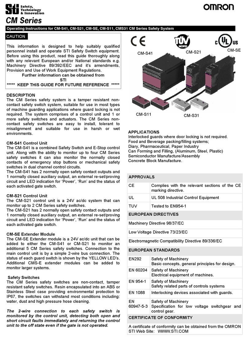
Omron STI CM Series User manual

Omron

Omron STI CM Series User manual

Omron SYSMAC CVM1-PRO01-V1 User manual

Omron

Omron SYSMAC CVM1-PRO01-V1 User manual

Omron CS1W-MC221 - User manual

Omron

Omron CS1W-MC221 - User manual

Omron SRM1-C01-V2 User manual

Omron

Omron SRM1-C01-V2 User manual

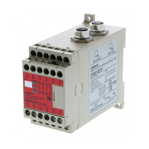
Omron F3SP-B1P User manual

Omron

Omron F3SP-B1P User manual

Omron CJ1W-PRT21 User manual

Omron

Omron CJ1W-PRT21 User manual

Omron F3SP-U5P User manual

Omron

Omron F3SP-U5P User manual

Omron CJ1W-NC214 - User manual

Omron

Omron CJ1W-NC214 - User manual

Omron NX-SL series User manual

Omron

Omron NX-SL series User manual

Omron C200HS-SNT32 User manual

Omron

Omron C200HS-SNT32 User manual

Omron SYSMAC 3G8F5-CLK11-E User manual

Omron

Omron SYSMAC 3G8F5-CLK11-E User manual

Omron CS1W-DRM21 User manual

Omron

Omron CS1W-DRM21 User manual

Omron 3G3AX-MX2-EIP-A User manual

Omron

Omron 3G3AX-MX2-EIP-A User manual

Omron SYSMAC SRM1-V2 User manual

Omron

Omron SYSMAC SRM1-V2 User manual

Omron GX-JC03 User manual

Omron

Omron GX-JC03 User manual

Omron GX-JC03 User manual

Omron

Omron GX-JC03 User manual

Omron CS1W-MC221 - User manual

Omron

Omron CS1W-MC221 - User manual

Omron SYSMAC LINK C1000H-SLK21-V1 User guide

Omron

Omron SYSMAC LINK C1000H-SLK21-V1 User guide

Omron SYSMAC C200H-NC111 User manual

Omron

Omron SYSMAC C200H-NC111 User manual

Omron SYSMAC C200H-ASC02 User manual

Omron

Omron SYSMAC C200H-ASC02 User manual

Omron C200HW-MC402-E User manual

Omron

Omron C200HW-MC402-E User manual

Omron CV500-MC221 User manual

Omron

Omron CV500-MC221 User manual

Omron CS1W-LC001 User manual

Omron

Omron CS1W-LC001 User manual

Omron G9SX-AD322-T15-RT User manual

Omron

Omron G9SX-AD322-T15-RT User manual

Popular Control Unit manuals by other brands

Honeywell PRO3200 installation guide

Honeywell

Honeywell PRO3200 installation guide

Allen-Bradley ControlLogix DeviceNet installation instructions

Allen-Bradley

Allen-Bradley ControlLogix DeviceNet installation instructions

Danfoss DHP-A Installation instruction

Danfoss

Danfoss DHP-A Installation instruction

Allen-Bradley POINT I/O 1734-VHSC5 user manual

Allen-Bradley

Allen-Bradley POINT I/O 1734-VHSC5 user manual

Siemens SIMADYN D MS51 user manual

Siemens

Siemens SIMADYN D MS51 user manual

Eneo VHM/H24W Mounting instructions

Eneo

Eneo VHM/H24W Mounting instructions

Olimpia electronics BS-465 manual

Olimpia electronics

Olimpia electronics BS-465 manual

Hyperion Emeter II quick guide

Hyperion

Hyperion Emeter II quick guide

Amerec PURE 2.0 operating instructions

Amerec

Amerec PURE 2.0 operating instructions

National Instruments NI 9221 Getting started guide

National Instruments

National Instruments NI 9221 Getting started guide

Vag GA Industries 939SS Installation, operation and maintenance manual

Vag

Vag GA Industries 939SS Installation, operation and maintenance manual

Linx Technologies FCTN-RLY4-315 manual

Linx Technologies

Linx Technologies FCTN-RLY4-315 manual

Control Techniques FM-3 Reference manual

Control Techniques

Control Techniques FM-3 Reference manual

Unitech TB160 quick guide

Unitech

Unitech TB160 quick guide

Emerson Fisher C407-10 instruction manual

Emerson

Emerson Fisher C407-10 instruction manual

Smarteck Electronics QT-06 user manual

Smarteck Electronics

Smarteck Electronics QT-06 user manual

Advantech ADAM-2510Z user manual

Advantech

Advantech ADAM-2510Z user manual

SMC Networks VHS20-D Series manual

SMC Networks

SMC Networks VHS20-D Series manual

manuals.online logo
manuals.online logoBrands
  • About & Mission
  • Contact us
  • Privacy Policy
  • Terms and Conditions

Copyright 2025 Manuals.Online. All Rights Reserved.