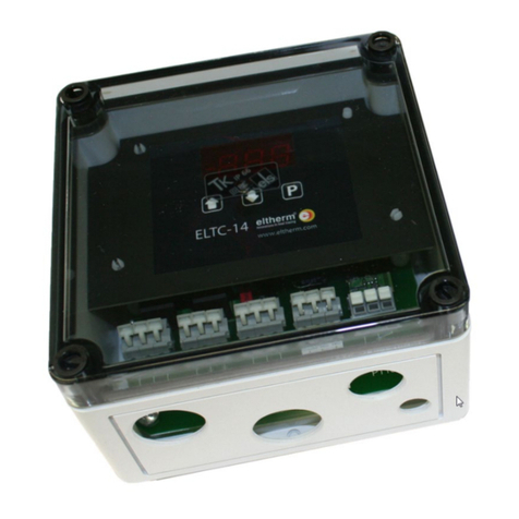
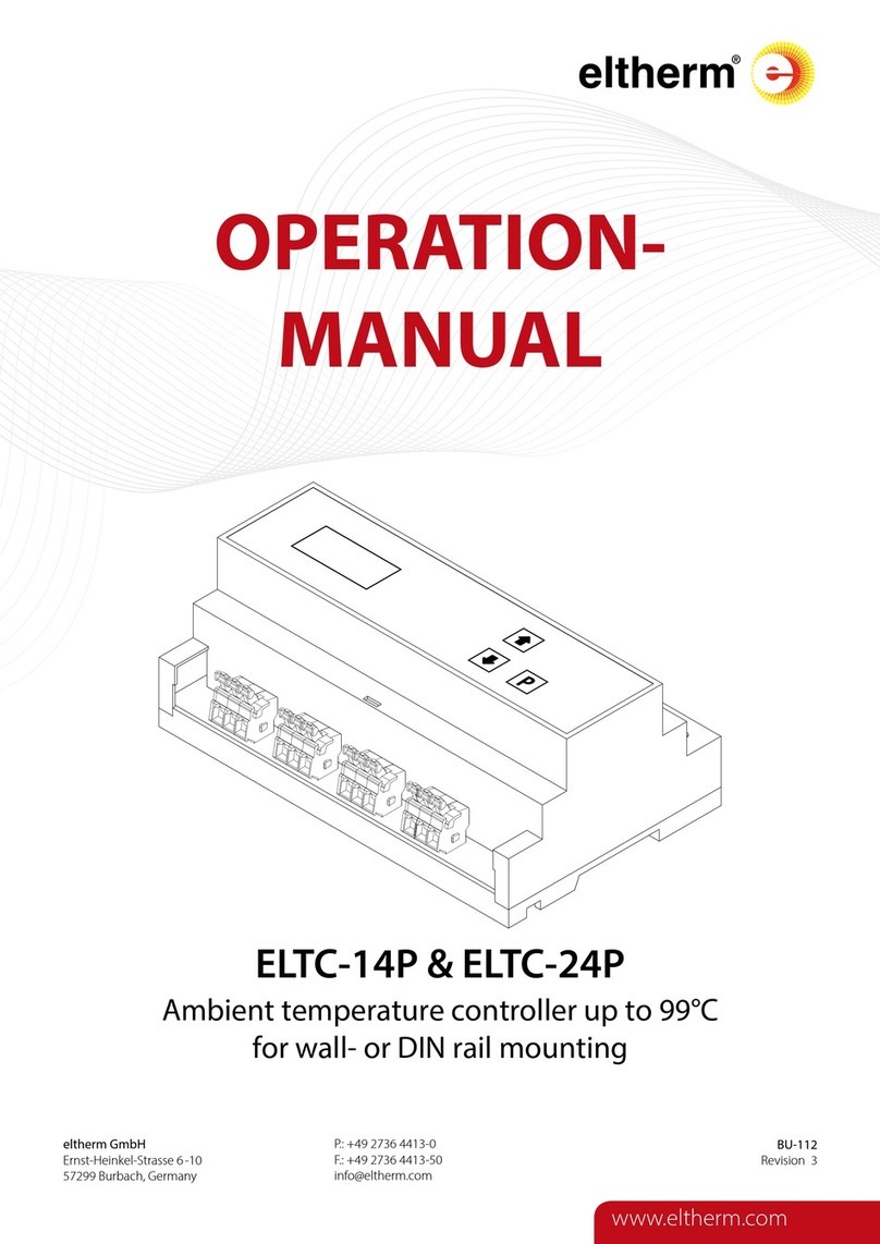
eltherm ELTC-W User manual

eltherm GmbH
Ernst-Heinkel-Str. 6-10
57299 Burbach, Germany
Fon: +49 (0)2736/4413-0 •Fax: +49 (0)2736/4413-50
E-Mail: info@eltherm.com •Internet: www.eltherm.com
WATER COMFORT SYSTEM
Operating manual
electronic temperature control unit for ELSR-W
Art.: 0630000
Type:
ELTC-W
eltherm Water Comfort System
–simply energy-saving
In modern society the supply of pure potable and non po-
table water, both hot and cold, is an important contribution
to comfort and well-being which should be readily available.
We assume that the water supply is clean and sterile, but
unfortunately this is not always true. An invisible threat to
health is legionella bacteria. These bacteria cause two kinds
of clinical problems, which behave differently in the course
of disease. One known as Legionnaires Disease normally
causes symptoms similar to pneumonia and can result in
death. The second one so called Pontiac Fever has symp-
toms like influenza but with quite rapid healing.
Legionella, especially in heated water between 30° and
45°C, can cause a threat to health, if small drops of water,
e.g. when taking a shower, are inhaled. Legionella formation
can be prevented by merely changing the water tempera-
ture. Cold water under 20°C and warm water over 55°C
constitute poor growth conditions for legionella bacteria,
therefore the water should be heated up to 60°C once a
day to purge the system. This procedure is called thermal
disinfection.
If the disinfection measures are incorporated in the planning
phase of a water line system, remarkable cost savings can
be achieved. However, retrofitting of a thermal disinfection
system is normally possible without any problems. It is
especially important to install the system in buildings which
present high risk of infection to the occupants, such as hos-
pitals, nursing homes and schools, but it also makes sense
to install the system in private housing.
The eltherm Water Comfort System provides the energy-
saving solution to keep warm water steadily available and to
fight legionella bacteria effectively.
Advantages of the eltherm Water Comfort System for you:
- High user friendliness by intuitive adjustment
- Simplified entry. A lot of details are already
preset for choice
- Logical and clear composed menu –no
confusing icons
- Complicated calculations to adjust the system
are not necessary
- An automatic operating mode ensures
legionella bacteria prevention even if the
system is not adjusted individually already.
- No overheating of the system because of
heating and heat maintenance with self-
regulating heating tapes.
- The moisture proof heating tape ensures
longer durability.
- The heating tape is available in three nominal
outputs.
- The length of the heating tape can be varied
freely as you can cut it to length from roll.
- An additional heating circuit for frost protection
in combination with a self-regulating
heating tape prevents freezing of an
additional cold water pipe.
- Cost saving up to 65%, because a circulation
system and a circulation pump is no longer needed.
- Considerable energy saving because of optimized
temperature gradation and abolition of the
circulation pump.
- An additional temperature sensor on the boiler
enables in ideal temperature maintenance balanced
between boiler and water pipes
- Ideally matching accessories enable an
individual design according to your require-
ments => a plug-and-play version is possible
if wished
- The system fulfills accepted international
standards for legionella avoidance (e.g.
Arbeitsblatt W 551 of DVGW in Germany)
- The system is approved by VDE and fulfills
the EN 61000-3-3/11.* That means, because of
the soft start function there is no flickering light
when energizing the heating tape.
The considerable simplification of installation makes the
eltherm Water Comfort Systems to the optimal solution for
drinking water heating and drinking water conduit facilities.
* "Flicker" Standard. Please contact us for details.
BU-091 - 008TCWE Firmware V0.5.0 Revision 3

Water Comfort System · Operating Manual Electronic Temperature Control Unit ELTC-W
Page 2 of 10 Firmware V0.5.0
Revision 3
BU-091 - 008TCWE
Circulation Pipe Electrical Heat Tracing
Warm water circulation system
This system consists of the warm water boiler, warm water pipe,
pump, valves, fittings, and a circulation pipe that is used for
temperature maintenance. The pipes are soldered or pressed
together using fittings.
A circulation pipe does not provide warm water all the way to
the water outlet. A waste of water takes place because the user
must wait until the cold water has left the pipe before the warm
water comes out.
A circulation pipe requires more room for installation,
it is more expensive to install (e.g. cutting the pipe to length,
soldering of fittings, more time = paying installers, etc) and
requires maintenance (e.g. Valve or its seal, and the pump
need replacement)
The operation of a circulation system requires more ener-
gy. (Increased surface and hence increased heat loss due
to double piping; power for pump.)
Warm water electrical heat tracing system
This system uses the same principle as the warm water cir-
culation system but does not require a circulation pipe, pump,
valves and fittings associated with the circulation pipe. Instead
a self-regulating heating cable is used for temperature mainte-
nance.
With electrical heat tracing warm water is provided all the way
to the water outlet. This saves water because the warm water is
readily available when opening the faucet.
This system requires less room because the heating cable is
placed directly on the warm water pipe. So it is less expensive
to install. It does not require maintenance.
With electrical heat tracing you can save up to 65 % of your
energy costs compared to a circulation system.*
Water Comfort System
2
51 Insulation (by Customer)
2 Water pipe (by Customer)
3 EL-Clic T-splice
4 Self-regulating heating cable ELSR-W
5 Self-adhesive aluminum foil
1 6 EL-Clic fast connector system
7 Water boiler (by Customer)
8 Controller
3
4
6 8
* Exemplary system: 1/2 " piping, heated length 10m, 15 mm thermal insulation,
7 power consumption of pump 75 W, maintain temperature 45°C, ambient tempera-
ture 15°C.

Water Comfort System · Operating Manual Electronic Temperature Control Unit ELTC-W
BU-091 - 008TCWE
Page 3 of 10 Firmware V0.5.0
Revision 3
Product description
• Electronic temperature control unit for heating cables on water pipes
Standard
functions
• LCD-Display with plain text, operation with 4 buttons
Operating / Operating elements
LCD-Display for
Parameters and data
cursor buttons
up/down
leave list
open list /
start programming /
confirm data
Alarm
On = Output activated.
Alarmbeeper can be accepted by pressing any button
Frost
protection
On = Output activated
Heating tape
On = Relay connected, P=100%
Blinking = soft start active, P < 100%
Operation
On = self test
Blinking = normal operation
Blinking quickly = fault operation
Programming
All readable and adjustable data (parameters) have been summarized in
lists. During normal operation or if no button is pushed for at least 1 minute
the following information appears:
Parameter lists
ELT
C
-
W
10
:
49[W
E]
>
S
ta
n
dard
-
m
od
e
Standard Display
Controller type Time (24h mode) ↓↑
ELT
C
-
W
10
:
49[W
E]
Working mode or
error message
Button Action
>
S
ta
n
dard
-
m
od
e
Weekday
RET
↓
ESC
↑
ESC
..........
> 3 seconds, back to general display
RET
...........
Open overview of parameter lists
........
select a parameter list
ELT
C
-
W
10
:
49[W
E]
1
)
B
ase
se
tti
ngs
→ RET
Grundeinstellungen
Base Settings
RET
...........
select a parameter list
........
select parameter to be programmed
RET
...........
start programming, parameter name blinks. ← ESC
Optionally an identification is required.
........
choose settings, keeping cursor button
pushed, accelerates the display of data.
ELT
C
-
W
10
:
49[W
E]
2)
S
e
t
u
p
→ RET
Sollwerte Einstellung
Settings
RET
...........
end programming
ESC
...........
brings you back to list overview. ← ESC
ELT
C
-
W
10
:
50
[
W
E
]
3
)
T
i
m
ers
→ RET
Zeiteinstellungen
Timers
← ESC
ELT
C
-
W
10
:
50
[
W
E
]
4
)
A
nt
i
fr
eeze
→ RET
Frostschutz
Frost Protection
← ESC
ELT
C
-
W
10
:
51
[
W
E
]
5
)I
n
f
o
→ RET
Information
Info
← ESC
Caution Please observe safety instructions!
ESC ..........> 3 seconds, back to general display
RET ..........Open overview of parameter lists
.........select a parameter list
RET ..........select a parameter list
.........select parameter to be programmed
RET ..........start programming, parameter name blinks.
Optionally an identification is required.
.........choose settings, keeping cursor button
pushed, accelerates the display of data.
RET ..........end programming
ESC ..........brings you back to list overview.
Identification
This display appears: Access Code
0 [1]
this parameter then protects against an inadvertent use by a code.
The controller requests the entering of the code 42.
After having entered the additional code the output switches
off. The reactivation will be effected by pressing the button
ESC for >3 seconds; after 60 seconds automatically without
keystroke: The code will be deleted again and the main
display will be activated at the same time.

Water Comfort System · Operating Manual Electronic Temperature Control Unit ELTC-W
Page 4 of 10 Firmware V0.5.0
Revision 3
BU-091 - 008TCWE
Technical Data
General Connection and Safety Instructions
Operating voltage range Input A
....................................100...253VAC,
50Hz
Operating voltage range Input B
...............................................24VDC,
± 5%
Max. power input
.....................................<=
6,5VA (@ 253VAC, worst case)
Standby power
input...................................................
<= 3,5VA (@ 230VAC)
Operating temperature range........................................................-10...+40°C
Storage temperature range...........................................................-20...+65°C
Admissible humidity
...............................................
80% RH, non-condensing
Relay outputs
Heating tape maximum current
......................20A
(res., max. 250VAC)
Heating Tape while Softstart
....................................................
max. 50A
Frost protection-Output maximum current.....16A(res., max. 250VAC)
Alarm-Output maximum current
.......................2A
(res., max. 250VAC)
requiered minimum current
.....................................10mA
/ 5VDC
Fuse protection
.....................................internal
2A, non-changeable cut-out
Advice
This manual has to be accessible to users at any time. We
cannot accept liability for damages caused by unintended
usage or by non-observance of the manual and the safety
instructions! In these cases all warranty claims are void.
This manual contains additional safety instructions within the
product description. Please observe!
If you detect damage, the product should NOT be connected
to voltage!
Current control…………………………………………………….limit 0,2 A
“error” corresponds 6 m heating cable in nominal rating
Inputs
........................................................2x
NTC-Temperature sensors
Measuring-/Display range
...................................................
max. -20...+60°C
Resolution .................................................................................................0,1K
Accuracy
..................................................................................
±1K, ±1 Digit
Display
..........................................................................LCD,
128x32 Pixel
Adjustment range
.............................................................
see parameter lists
Interface
..........................
RS 485, half duplex, 8N1, max 38,4 kBaud
Communication protocol
.......................................................................
E-Link
Data preservation
..............................................................................
unlimited
Clock
.........................................Quartz,
automatic daylight saving time.
Runtime without line voltage
.......................................................
typ. 10 days
Housing
...................................................................
Plastic with foil buttons
for standard busbar 35mm, IP 20
Danger It presents a danger to life!
Asafe operation might not be possible if:
• the device has visible damage,
• the device does not work,
• after longer storage in inappropriate conditions.
• contamination or humidity.
• after hard transport stress.
• Installation and operation of the device must be
carried out bya certified electrician or under
observation bya certified electrician.
• Keep the device safelydisconnected from voltage
while mounting.Danger of electric shock!
• Never operate the device without housing.
Danger of electric shock!
• An existing PE-terminal of the device mustbe put on
PE! Danger of electric shock!Additionally
the internal filtering of errors would only function
partly, so deficient displays can be the result.
• The devicemust only be used for the purpose
described in this document.
• Please observe the required safetyregulations and
standards in the place of installation.
• Before usage of the controller please check its operating
conditions (see technicaldata),e.g.:
Caution
Advice
- Power supply(printed on the device)
- Required ambient conditions
(temperature or humidity limits)
- Maximum stress to the relay contacts in relation with
the maximum starting currents of the users (e.g.
engines, heaters).
In case of non-observance malfunctions or damages
are possible.
• Observe when extending sensor cables:The cross
section is uncritical but should be 0,5mm² minimum.
Thinnercables can cause error displays.
• Avoid installation directly next to big contactors (strong
interferencesare possible).
• Please observe the necessary requirements when
installing data lines.
CleaningDonotuseacidoracidicmeanstocleanthefront
foil.Danger of damage!
We declare that the described product is in full compliance with
the directives 2006/95/EC, 2004/108/EC and 2011/65/EU. If you
RoHS need a detailed declaration of conformity, please contact us.

Water Comfort System · Operating Manual Electronic Temperature Control Unit ELTC-W
BU-091 - 008TCWE
Page 5 of 10 Firmware V0.5.0
Revision 3
Function Description
Normal Operation
The heating cable output is adjusted by a hybrid relay in a frequency ratio
tuned to seconds (period time 10 min.). The frequency ratio is calculated on
the basis of mathematical models of the actual power loss of the pipe and
the actual power of the tape.
With every newstart (also after holiday) the heater is activated for 2 hours to
start legionella protection. Before switching on the relay a soft start always
takes place first to reduce the switching current for the relay (20 sec.).
a) Timer Operation
As long as the parameter "Follow Boiler" is not switched to "1", the ELTC-W
works in the timer mode. That means, depending on weekday and time the
stored program is used. A pre-heating period is implemented (Pre-Pow- er)
to have the set temperature reached when the chosen timer operation
starts.
When the temperature is reached, the controller switches to maintenance
temperature.
The following steps are allotted tothe timer program accordingly:
0 Output fixed to 0%.
1 The parameter"Economy Mode" is used as set temperature.
2 The parameter"HoldingTemp" is used as set temperature.
3 Legionella Protection →fixed target temperature is 60° C.
b) Trace Boiler Operation
Is activated by switching parameter "Trace Boiler"on "1". After that the no-
minal value is exclusively determined by the external boiler temperature
sensor. That means, the timer adjustments will be ignored. If this external
sensor measures a temperature higher than the one of parameter "Boiler
Leg.Temp.",theoutputis setto100% power tosupportlegionella protection.
If a sensor failure is detected at the boiler temperature sensor, an alarm is
activated and the heating cable output is switched off.
c) HolidayOperation
As soon as for the parameter "Vacation until" a date in the future is entered,
the ELTC-W switches to holiday mode and the power output is deactivated
permanently. When this date is reached (0:00 o'clock) legionella protection
is activated for 2 hours (output set to 100%). After that the timer program is
continued according to the actual date/time.
On the daily date switch (23:59 -> 0:00) the output is operated for a deter-
mined time of 2 hours for legionella bacteria reduction with 100% power. On
the display the remaining time (round up number of days) with a maximum
of 99 days is shown (which means, if the remaining time is under 24 hours
the displayshows 1 day).
Frost Protection
Bysettingthe parameter "ActivateA.F." the frost protectionfunction is activa-
ted. By a separate sensor input the actual temperature is compared with
the value of the parameter "Switch-On".As soon as the value is reached (or
un- der-run) the output is activated to run the heating tape. As soon as the
value "Switch-On" + "Hysteresis" isexceeded, the output is switched off.
To avoid fast switching cycles a minimum standstill period of 60 seconds is
implemented (that means, after each switch-off of the relay, the re-switch-on
is blocked for 60 seconds). If a sensor failure occurs, the alarm relay is set
and the output is (permanently) switched-off.
Maximum Operation
If level 3 within the timer programming is chosen, the target temperature of
60° C is assumed.Whenthe temperature is reached, the controller switches
to cyclic operation to maintain the temperature.
Operation Types (Modes)
Standard Mode .......................The heating power is regulated to reach
the set maintenance temperature
Eco-Mode
...............................
The heating power is regulated to reach
the set power saving temperature
Standby
mode
...............................
The heating power is shut down to 0
Pmax Mode..........................Theheating power is regulated to maintain
60°C for legionella bacteria prevention
Pre-Heating-Up
...........................
The calculated time until reaching the
next desired value level
Trace Boiler Function................Thetimer mode is deactivated and the
boiler temperature is used as desired value
Holiday
Mode
.....
allows to choose a deactivation period for the heating
Failure / Status Reports
no heating tape
............................
no heating tape found or loadcurrent less
than 0.2A; Heating tape
possibly too short (<6m),
not connected, line
interruption or defective
no time
......................................................................no
timer settings made,
possibly the controller was switched off for longer time,
over temperature
..............................................
inner case temperature >60°
relay defect
..............................................
short-circuit of heating tape output
internal failure
.......................................restart
controller, if failure still occurs
contact eltherm GmbH
F.P.Sensor................frostprotectionsensordefect / breakage / short-circuit
Boiler
......................................
boiler sensor defect / breakage / short-circuit
>Holiday..........................Controlleris in holiday mode for xx days (xx days)

Water Comfort System · Operating Manual Electronic Temperature Control Unit ELTC-W
Page 6 of 10 Firmware V0.5.0
Revision 3
BU-091 - 008TCWE
Parameterliste
1) Grundeinstellungen
Werkseinstellung .............
Sprachauswahl ................
...................................
Datum...............................
...................................
...................................
Zeit ...................................
...................................
...................................
2) Setup
Haltetemperatur................
...................................
...................................
Spartemperatur.................
...................................
...................................
...................................
Typ Heizband....................
...................................
Umgebungs Temp. ...........
Rohr Durchmesser ...........
Rohr Isolierung.................
Korrekturfaktor..................
...................................
3) Timer
Folge Boiler ......................
...................................
...................................
Boiler Leg.Temp................
...................................
Urlaub bis .........................
...................................
...................................
...................................
Timer ................................
Mo ...................................
Di ...................................
Mi ...................................
Do..................................
Fr...................................
Sa...................................
So...................................
4) Frostschutz
Aktiviere F.S......................
...................................
Einschaltpunkt ..................
Hysterese .........................
...................................
5) Information
Build / Version...................
Temp. Boiler......................
Temp. Frostschutz ............
Temp. Intern G..................
Temp Intern A ...................
Ip Heizband ......................
Parameter Listing
1) Base Settings
..(Default Settings)........
..Language Select ........
......................................
..Date Settings..............
......................................
......................................
..Time Settings..............
......................................
......................................
2) Setup
..Maint. Temp................
......................................
......................................
..Economy Mode ..........
......................................
......................................
......................................
..Tape Type...................
......................................
..Ambient Temp.............
..Pipe Diameter.............
..Pipe Insulation............
..Correct. factor.............
......................................
3) Timers
..Trace Boiler................
......................................
......................................
..Boiler Leg.Temp. ........
......................................
..Vacation until..............
......................................
......................................
......................................
......................................
..Mo ...............................
..Tu
................................
..
We...............................
..
Th...............................
..Fr..................................
..Sa.................................
..Su.................................
4) Frost Protection
..Activate A.F.................
......................................
..
Switch-On...................
..Hysteresis...................
......................................
5) Info
..Build / Version ............
..Temp. Boiler ...............
..Temp. Antifreeze.........
..Temp Internal G..........
..Temp Internal A...........
..Ip Heating Tape .........
Description
factory settings (set on 3 and confirm)...............................
language shown in display.................................................
............................................................................................
Date setting of internal clock. Current date; The ELTC-W
automatically recognizes daylight saving time
according to set date (Display "W" or"S") ..........................
Time setting of internal clock. Current time; The ELTC-W
automatically recognizes daylight saving time
according to set date (Display "W" or"S") ..........................
standard desired value
The ELTC-W will maintain this temperature, if timer
program is set to "2"........................................................
standard desired value → the upper limit depends on
the set temperature for Maint Temp.
The ELTC-W will maintain this temperature, if timer
program is set to "1"........................................................
Select the heating tape. Selection between ......................
ELSR-W-55 and ELSR-W-65.............................................
The minimum expected temperature at pipe location........
The diameter of water pipe ................................................
The thickness of insulation.................................................
Can be used to adjust the internally calculated power
output to local conditions ...................................................
If the Trace Boiler function is activated, the ELTC-W ........
will follow the temperature of the boiler. Therefore
a temperature sensor is needed at boiler surface..............
If boiler probe detects this temperature or above
legionella protection is activated .......................................
Range
..1-3
..0 = English, ......
..1 = German
..dd.mm.yyyy
..hh:mm:ss
..
37°...68°C.........
..
37°...68°C.........
..ELSR-W 65 ......
..ELSR-W 55
..0...25°C............
..15...100mm ......
.. 9...100mm......
..50...150%.........
............................
..0...1..................
..
50°...60°C.........
Factory Settings
....0
....45°C
....40°C
....ELSR-W 65
....10°C
....15mm
....9mm
....100%
....
....0
....50°C
As soon as for the parameter "Vacation until" a date in the future is entered, the ELTC-W
switches to holiday mode and the power output is deactivated permanently. When this date is
reached (0:00 o'clock) legionella protection is activated for 2 hours (output set to 100%).
After that the timer program is continued according to the actual date/time.
The ELTC-W has different preset working modes. This.....
working modes describe the behavior of the heater.
0= no heating
1 = Economy Mode
2 = Maint Temp. .................................................................
3 = Legionella Protection
...................................................
You also have the opportunity to set an individual
............
program for each day
......................................................
............................................................................................
............................................................................................
............................................................................................
............................................................................................
............................................................................................
To activate frost protection function switch to "1"
To use frost protection a temperature sensor is needed....
The ELTC-W will maintain this temperature.......................
Hysteresis prevents rapid switching on and off as the
temperature drifts around the set point..............................
Version and Software Version of device
actual measured boiler temperature
actual measured frost protection temperature
actual measured inner-case temperature No.1
actual measured inner-case temperature No.2
actual measured peak current of heating tape
..Home
Apartment Hou
Restaurant
Hotel
..constant temp.
..individual
..Monday
..Tuesday
..Wednesday
..Thursday
..Friday
..Saturday
..Sunday
..0...1 (on)...........
..-10...+30°C
.......
..1...10K
..............
se
....0 (off)
....2°C
....1K
Parameter Listing

BU-091 - 008TCWE
Page 7 of 10 Firmware V0.5.0
Revision 3
Water Comfort System · Operating Manual Electronic Temperature Control Unit ELTC-W
Timer Adjustment
With the ELTC-W you can adjust the timer for each day of the week
individually. Therefore you can use the pre-selected functions like home,
restaurant or constant Temp. or you can adjust the day by half an hour
steps.
Select "Timers" within the menu with the curser key and press RET.
Select > Customized< with the cursor key and press RET.
The display shows see the daily temperature curve which can be adjus-
ted according to your needs.
Again select >Customized< with the cursor key and press RET.
You start with 0:00 o'clock.
By pressing the cursor keys you can now select between
0 = No Heating
1 = Economy Mode
2 = Maint. Temp.
3 = Legionella Protection
To select the desired function just press RET again.
You will proceed in half an hour steps. If you want to have the same ad-
justments for several hours in follow, just press RET step by step until
you reach the time where you want to change the adjustment again.
You can always leave the menu by pressing the ESC-key.
The following example shows how to adjust the timer:
It is possible to transfer the same adjustment from one day to another
day:
After selection of the weekday you want to adjust, select the weekday
you want to transfer instead of >customized<.
Pre-selected functions of the Timer
There are different pre-selected functions of the timer that can be selected
according to the user’s needs. So the user does not have to adjust the timer
individually.
Constant Temperature
The adjusted maintenance temperature is kept the whole day long. That
means: parameter is constantly set on "2".
Home
00.00 - 01.00 Uhr Legionella protection ("3")
01.01 - 06.00 Uhr No heating ("0")
06.01 - 08.00 Uhr Maint. temp. ("2")
08.01 - 11.00 Uhr Economy Mode ("1")
11.01 - 13.00 UhrMaint. temp. ("2")
13.01 - 16.00 Uhr Economy Mode ("1")
16.01 - 22.00 Uhr Maint. temp. ("2")
22.01 - 23.59 Uhr No heating ("0")
enter menu
ELT
C
-
W
10
:
49[W
E]
>
S
ta
n
dard
-
m
od
e
Standard Display
Restaurant
00.00 - 02.00 Uhr Economy Mode ("1")
02.01 - 03.00 Uhr Legionella protection ("3")
03.01 - 06.30 Uhr No heating ("0")
06.31 - 08.00 Uhr Economy Mode ("1")
select function "Timer"
press
select with
cursor key
RET
↓↑
08.01 - 09.30 Uhr Maint. temp ("2")
09.31 - 11.00 Uhr Economy Mode ("1")
11.01 - 15.00 UhrMaint. temp. ("2")
15.01 - 17.00 Uhr Economy Mode ("1")
17.01 - 23.57 Uhr Maint. temp. ("2")
ELT
C
-
W
10
:
49[W
E]
3
)
T
i
m
e
r
s
Select Display
Apartment House
00.00 - 01.00 Uhr Legionella protection ("3")
01.01 - 04.00 Uhr No heating ("0")
select weekday
press
select with
cursor key
RET
↓↑
[
W
E
]
Select Display
04.01 - 05.00 Uhr Economy Mode ("1")
05.01 - 06.00 Uhr Maint. temp. ("2")
06.01 - 08.30 Uhr Economy Mode ("1")
08.31 - 11.30 Uhr Maint. temp. ("2")
11.31 - 12.30 Uhr Economy Mode ("1")
12.31 - 16.30 Uhr Maint. temp. ("2")
16.31 - 17.00 Uhr Economy Mode ("1")
>
C
u
s
t
o
m
i
ze
d
<
17.01 - 18.00 Uhr Maint. temp. ("2")
18.01 - 20.00 Uhr Economy Mode ("1")
select pre-installed function
or >customized<
press
select with
cursor key
RET
↓↑
[
W
E
]
Select Display
20.01 - 21.30 Uhr Maint. temp. ("2")
21.31 - 23.00 Uhr Economy Mode ("1")
23.01 - 23.59 Uhr No heating ("0")
Hotel
00.00 - 01.00 Uhr Legionella protection ("3")
01.01 - 05.00 Uhr Economy Mode ("1")
>
C
u
s
t
o
m
i
ze
d
<
05.01 - 06.00 Uhr Maint. temp. ("2")
06.01 - 09.00 Uhr Economy Mode ("1")
if chosen >customized<
select between 0, 1, 2, 3
press
select with
cursor key
RET
↓↑
[
W
E
]
Select Display
09.01 - 12.00 Uhr Maint. temp. ("2"
12.01 - 13.00 Uhr Economy Mode ("1")
13.01 - 16.30 Uhr Maint. temp. ("2")
16.31 - 17.00 Uhr Economy Mode ("1")
17.01 - 18.00 Uhr Maint. temp. ("2")
18.01 - 20.00 Uhr Economy Mode ("1")
20.01 - 21.00 Uhr Maint. temp. ("2")
0
:
00
[
]
1
select with ↓↑
cursor key
21.01 - 21.30 Uhr Economy Mode ("1")
21.31 - 22.00 Uhr Maint. temp. ("2")
22.01 - 23.59 Uhr Economy Mode ("1")
press RET
Repeat this until you have
adjusted from 0:00 to 23:30
o'clock.
To leave menu
press
ESC
Select Display
Select Display
Select Display

Page 8 of 10 Firmware V0.5.0
Revision 3
BU-091 - 008TCWE
Water Comfort System · Operating Manual Electronic Temperature Control Unit ELTC-W
230 V
max C20 A
Controller
Current
47
(1.85)
63 (2.48)
93
(3.66)
ELSR-W...
Heating Tape
35 (1.38)
Dimensions and Wiring
153
(6.02)
59
(2.32)
39
(1.54)
26
(1.02)
There are three wiring schemes for the temperature controller.
LED-Operation
230V
supply input B
24VDC Interface
Service-
Port
sensor inputs
Frost
Protection
Boiler
(-) (+) DO NDO Gnd Gnd F1 Gnd F2
2 A
N-Block PE-Block
N N N
PE PE PE
L(A) L1 L1 L (heating tape)
Com NO Com NO NC
frost
protection
output
max
16
A
alarm-
output
max 2
A
L(A) = supplyvoltagecontroller(ELTC-W)
L1 = supplyvoltage heating tape
L=heatingtapeoutput
WiringScheme 1:
Separate feeders for controller device and heating circuit.

BU-091 - 008TCWE
Page 9 of 10 Firmware V0.5.0
Revision 3
Water Comfort System · Operating Manual Electronic Temperature Control Unit ELTC-W
230 V
max C20 A
ELSR-W...
Heating Tape
LED-Operation
230V
supply input B
24VDC Interface
Service-
Port
sensor inputs
Frost
Protection
Boiler
(-) (+) DO NDO Gnd Gnd F1 Gnd F2
2 A
N-Block PE-Block
N N N
PE PE PE
L(A) L1 L1 L (heating tape)
Com NO Com NO NC
Advice
frost
protection
output
max 16
A
alarm-
output
max 2
A
L(A) = supplyvoltagecontroller(ELTC-W)
L1 = supplyvoltage heating tape
L=heatingtapeoutput
WiringScheme 2:
If the heater and the temperature controller are connected on same feeding
circuit, the system has to be protected with C 20Amax.
Advice
Advice:
If controllerand heatingcable are using a commonsupplycon-
nect "L1" to "L(A)" .

Page 10 of 10 Firmware V0.5.0
Revision 3
BU-091 - 008TCWE
Water Comfort System · Operating Manual Electronic Temperature Control Unit ELTC-W
230 V
max C20 A
24 VDC
ELSR-W...
Heating Tape
LED-Operation
230V
Interface
Service-
Port
sensor inputs
Frost
Protection
Boiler
(-) (+)
supply input
B
24VDC
DO NDO Gnd Gnd F1 Gnd F2
2 A
N-Block PE-Block
N N N
PE PE PE
L(A) L1 L1 L (heating tape)
Com NO Com NO NC
frost
protection
output
max 16
A
alarm-
output
max 2
A
L(A) = supplyvoltagecontroller(ELTC-W)
L1 = supplyvoltage heating tape
L=heatingtapeoutput
WiringScheme 3:
Connect separate 24 VDC supply for controller asshown above.
This manual suits for next models
1
Table of contents
Other eltherm Temperature Controllers manuals

eltherm
eltherm ELTC/H-14 User manual

eltherm
eltherm ELTC-14P User manual

eltherm
eltherm ELTC-41 User manual

eltherm
eltherm ELTC/L-15 User manual

eltherm
eltherm ELTC-14 User manual

eltherm
eltherm ELTC-15 User manual

eltherm
eltherm ELTF User manual

eltherm
eltherm ELTC-14 User manual

eltherm
eltherm ELTC-15 User manual

eltherm
eltherm ELTC-14 User manual
Popular Temperature Controllers manuals by other brands

Hioki
Hioki 9021-01 instruction manual

elsner elektronik
elsner elektronik KNX T-AP Installation and adjustment

Danfoss
Danfoss 102E5 Installation and user guide

ACS
ACS 3200 Series Custom manual

Siemens
Siemens SITRANS Series Compact operating instructions

Elsner
Elsner KNX T-UN Technical Data and Installation Notes