Hugo Müller 879 410 LED User manual

BA 879 410-led HM; DE, GB - 23642 - 2016.05-V01
Hugo Müller GmbH & Co KG│Sturmbühlstraße 145-149│D-78054 VS-Schwenningen│Tel.: +49 (0) 7720 80 836│Fax: +49 (0) 7720 31 083│[email protected]│www.hugo-mueller.de
INSTRUCTION MANUAL TRIAC DIMMER [R,L] – 879 410 LED
Technical Features Safety instructions
Supply voltage 230 V, 50 Hz CAUTION!! DANGER OF LIFE / RISK OF FIRE AND ELECTRIC SHOCK!!
Installation and assembly of electrical equipment must be carried out only by
professional electrician!
Connect to supply voltage/frequency as stated on the product!
Disconnect device from power supply for wiring and installation purposes! Check power supply is disconnected!
Defective devices have to be put out of service immediately!
Warranty void if housing opened by unauthorized person!
Electronic circuit is protected against a wide range of external influences. Incorrect operating may occur if external influences exceed certain limits!
Installation and assembly of electrical equipment must be in accordance with local building and electrical codes!
Important note
When calculating the max. load please take into account power dissipation of transformers: For conventional transformers ~20% power dissipation /
For electronic transformers ~2% power dissipation.
For all transformers and lamps, please take into account the specifications of the manufacturer!
Intended use
The device fits for the particular use of the following tasks: dimmer for the previously defined lamps.
Operate the device in a closed room only! The regulation of the brightness operates as described in the instruction manual.
The device is equipped with a overheat protection and short-circuit protection.
Power consumption 3 VA
Type of lamps dimmable LED lamps
LOADS
Dimmable 230 V LED lamps
for leading edge 4 - 1200 W
Max. number of pushbuttons unlimited
(no illuminated pushbuttons)
Dimensions 87,5 x 87,5 x 60 mm
Weight 400 g
Working temperature 0 º … +40 ºC
Storage temperature -30 º … +70 ºC
Type of protection IP20 nach DIN EN 60529
According to the norm DIN EN 60669-2-1
Description / Installation
Operation
Description / Intended use
TRIAC dimmer for DIN-rail mounting
Use with dimmable LED lamps
For leading edge
The device is equipped with a overheat protection and short-circuit protection.
Unlimited number of pushbuttons (no illuminated pushbuttons), potentiometer (internal or external) or 0 - 10V
signal.
Seven basic functions (MEM, NO MEM, MEM PLUS, 0 - 10V, SLAVE, int. & ext. potentiometer).
Check the technical specification of the lamps! For all transformers and lamps, please take into account the
specifications of the manufacturer!
Installation
CAUTION! You must select the correct type of connected load in order to avoid damages of the
dimmer or the lamps!
1. Set an operating mode with the lateral rotary knob.
2. Disconnect device from power supply for wiring and installation purposes! Check power supply is
disconnected!
3. Mount the dimmer on the DIN-rail of the electric cabinet. Avoid placing it next to other sources of heat.
4. Carry out the wiring according to the selected operating mode.
5. Reconnect the power supply. The dimmer is ready for operation.
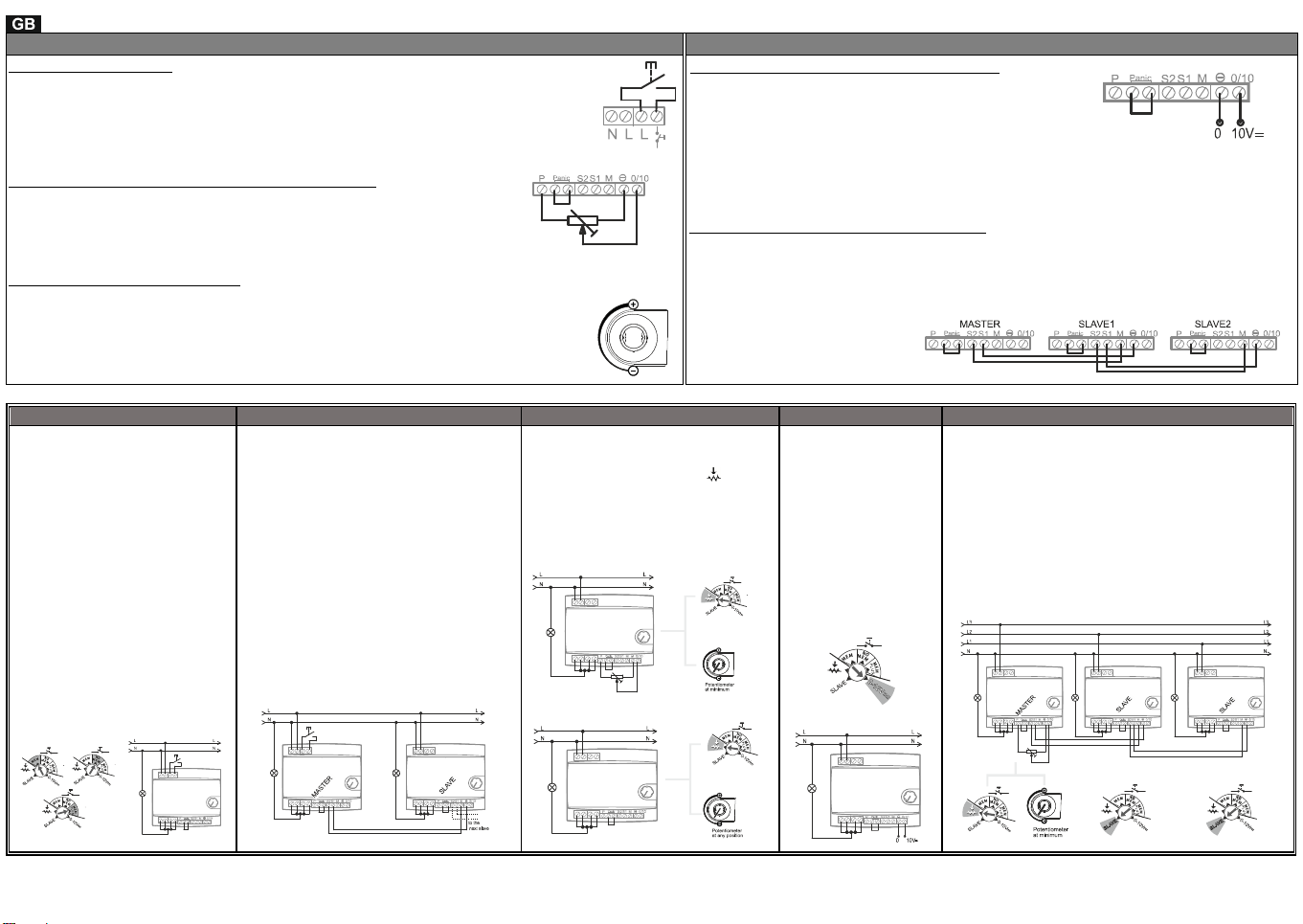
Anti-panic function
If you open the contact between the two terminals, the dimming function
overloads and the installed load/loads illuminate with maximum power.
You need this function especially in emergency situations. With removing
the bridge, the dimmer goes to maximum load and does not react to standard commands. If you do not use this
function, you have to keep the bridge between the terminals closed. The dimmer works in the standard mode
then.
Operation / functionality
The dimming can be performed with different controls, depending on the
configuration selected:
SLAVE Master-Slave Mode
Potentiometer (intern or extern)
MEM Pushbutton operation – Memory function
NO MEM Pushbutton operation – No memory function
MEM PLUS Pushbutton operation – Memory function with
additional safety function in case of power failure
0-10V Signal 0 - 10V
Protection against over heat
Protection against over heat switches off the lamps.
Note: If the dimmer is switched off due to over heat protection, please try to:
Reduce the output load.
Install the dimmer inside an electric cabinet with forced ventilation or without other heat sources,
or place it in the lower part of the cabinet, where the accumulation of heat may be lower.
Selector switch for LED lamp type
The device has a selector switch with 3 modes of operation: LEDA, LEDB, LEDC.
Change the selected mode if you notice that the LED lamps blink or change light level
suddenly at
some point of the dimming. Select the mode that fits to the characteristics of your LED
lamp best.

BA 879 410-led HM; DE, GB - 23642 - 2016.05-V01
Hugo Müller GmbH & Co KG│Sturmbühlstraße 145-149│D-78054 VS-Schwenningen│Tel.: +49 (0) 7720 80 836│Fax: +49 (0) 7720 31 083│[email protected]│www.hugo-mueller.de
INSTRUCTION MANUAL TRIAC DIMMER [R,L] – 879 410 LED
Operating modes Operating modes
Operation with pushbutton
Pressing the pushbutton shortly turns the load on and off.
Pressing the pushbutton for a long time carries-out a cyclical dimming (as long as the
pushbutton is pressed).
In this operation mode the internal potentiometer defines the lower dimming limit (pushbutton
MEM, NO MEM or MEM PLUS). It avoids flickerings or undesired switching-offs.
Operation with external potentiometer (galvanically isolated)
It is possible to control the load with a 10 kΩpotentiometer.
At the minimum level of the potentiometer the load stays turned off.
By turning the potentiometer, the load increases.
It is necessary to set the built-in potentiometer at minimum.
Operation with internal potentiometer
It is possible to control the load with the internal potentiometer of the dimmer.
By setting the potentiometer to the minimum value, the use of an external potentiometer is
possible.
If you put the potentiometer to any value higher than the minimum value, the potentiometer
will only consider this value. It will ignore the signals of the external potentiometer.
Operation with signal 0 - 10V (galvanically isolated)
0V correspond to a switched off status.
10V correspond to the maximum illumination of the dimmer.
You can use any external, isolated or not isolated voltage source
with 0 - 10 V (SPS, control panel etc.).
In this mode of operation the internal potentiometer defines the minimum dimming level. It avoids
flickerings or undesired switching-offs.
Master-Slave-configuration (galvanically isolated)
This configuration is used, if the maximum load that is supported by one dimmer is exceeded. With
this configuration it is possible to distribute the load across multiple dimmers and extend the load. For
this it is necessary to spread the load into several partial loads with each dimmer controlling its
maximum load. It is also recommended to use slaves in applications where different loads have to be
controlled. In this mode of operation the internal potentiometer defines the minimum dimming level. It
avoids flickerings or undesired
switching-offs.
Example 1 Example 2 Example 3 Example 4 Example 5
Operation with pushbutton
Place the selector switch in the
desired working mode:
MEM to switch on at the
same level as turned off.
NO MEM to switch on
with maximum power.
MEM PLUS to switch on
at the same level as
turned off and to rebuild
the operating status (turn
on/ off or level of
intensity) after power
failure.
Operation with pushbutton, extended by
slaves
The MASTER dimmer must be set
according to example 1.To configure a
dimmer as SLAVE, the selector switch
must be in SLAVE mode.
It is possible to add an unlimited number
of slaves.
There can be a time delay in the
response if you use a large number of
salves.
The heat development in the installation
box has to be monitored, especially when
using a larger number of dimmers.
It is recommended to realize a spacing
between each dimmer (1 module
spacing).
Operation with potentiometer
The selector switch must be in the
correct position for the
potentiometer
The brightness level depends on the
position of the potentiometer.
Turning the potentiometer clockwise
will increase the light intensity.
A) Operation with ext. potentiometer
B) Operation with int. potentiometer
Operation with 0 - 10V
signal
The selector switch
must be in the
correct position 0 -
10V.
Level 0V
corresponds to the
status switched off.
The light intensity
increases in the
same amount as the
voltage does to 10V.
3-phase-installation controlled by potentiometer
and increased by slaves
Do the installation according to the wiring diagram.
The MASTER dimmer must be configured as in
example 3A. The slaves must be in position SLAVE.
It is recommended to distribute the loads between
the three phases.
In case of three-phase line without electrical neuter,
please contact us.
Popular Dimmer manuals by other brands

Acclaim Lighting
Acclaim Lighting AL-DIMMER-1 HP User instructions

Arlight
Arlight SR-2828CCT quick start guide

Lutron Electronics
Lutron Electronics MRFA-3LD-URC quick start guide

EuroLite
EuroLite DPMX-1216 DMX Series user manual

movie-intercom
movie-intercom RC4 quick start guide

Ltech
Ltech LT-311RF manual

Lutron Electronics
Lutron Electronics HD-RD installation instructions

Intermatic
Intermatic HA06 supplementary guide

NuTone
NuTone Z-Wave NPD300Z quick start guide

Zennio
Zennio Lumento X2 v2 quick start guide

MICROPOINT
MICROPOINT mLabs Multi-level D-Dimer Control Level I manual

ETEKCITY
ETEKCITY ESWD16 user manual